
Related Manuals for CHAFFOTEAUX 35 FF


Summarization of Contents
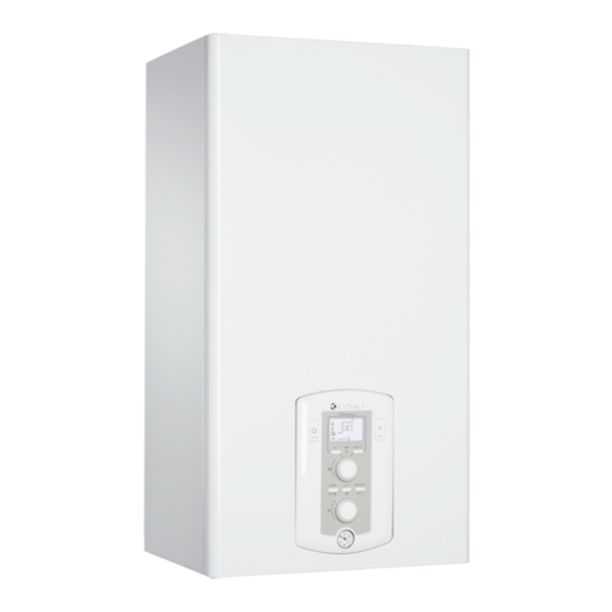
General
Safety Regulations
Key safety warnings and symbol meanings for installation and use.
Safety Key to Symbols
Explains the meaning of safety warning symbols used throughout the manual.
Warnings
Advice for the installer
Essential advice for installers regarding appliance use, compliance, and responsibilities.
Before installing the appliance
Checks and considerations required before the appliance is installed.
Warnings
Recommendations
Recommendations for lightning protection and warranty conditions.
Location of the Boiler
Guidelines for selecting a safe and suitable location for the boiler installation.
Planning and Carrying Out Installation
Steps and considerations for planning and executing the boiler installation.
Warnings
Cleaning the heating system
Instructions for cleaning the heating system to ensure proper boiler operation.
CE labelling
Guarantees appliance conformity with specified EU directives.
Warnings
Connecting the Flue
Detailed instructions for connecting the flue gas exhaust and air intake systems.
Types of boiler - flue exhaust connection
Describes various configurations for flue gas exhaust and air suction connections.
Warnings
Electrical connections
Guidelines for safe and correct electrical connections to the boiler.
Important!
Emphasizes fixed connection, bipolar switch, and prohibits multiplugs/adaptors.
Product description
OVERALL VIEW
Diagram showing the overall view of the boiler with numbered components.
Legend
List of components with their corresponding numbers from the overall view diagram.
Product description
WATER CIRCUIT DIAGRAM
Diagram illustrating the internal water circuit of the boiler for PIGMA and PIGMA SYSTEM.
Product description
OVERALL DIMENSIONS
Dimensional drawings for PIGMA 25/30 FF and PIGMA 35 FF models.
Minimum clearances
Specifies minimum clearances around the boiler for maintenance access.
INSTALLATION TEMPLATE
Provides a template for correct boiler positioning and connection points.
Product description
Hydraulic/gas connection
Information on available connection kits for different installation needs.
Hydraulic Bar Kit
Instructions for assembling the optional hydraulic bar kit for water/gas connections.
Installation
Cleaning the heating installation
Procedure for cleaning the heating system to prevent damage and ensure efficiency.
Residual Head of the Boiler AT 20°C
Graph showing residual head values for pipe and heating body sizing.
Tank connection - PIGMA SYSTEM
Instructions for connecting the boiler to a domestic hot water tank.
Installation
Boiler installation
Step-by-step guide for mounting the boiler onto the wall bracket.
Excess pressure device
Instructions for correctly installing the excess pressure device discharge pipe.
Installation
Flue gas exhaust / air suction duct connection
Details on connecting flue gas exhaust and air suction ducting systems.
Table of flue gas exhaust duct lengths
Table specifying maximum flue gas exhaust duct lengths for different configurations.
Installation
Type of air suction/flue gas exhaust ducting
Diagrams illustrating various types of air suction and flue gas exhaust ducting systems.
Installation
Electrical connections
Guidelines for safe and correct electrical connections to the boiler.
Important!
Emphasizes fixed connection, bipolar switch, and prohibits multiplugs/adaptors.
Room thermostat connection
Instructions for connecting a room thermostat to the boiler control panel.
Installation
Peripheral unit connection
Wiring diagram for connecting various peripheral units to the boiler.
Display
Shows the boiler's display and the function of its indicators.
C.H. Return temp. probe
Details the connection for the central heating return temperature probe.
Commissioning
Initial procedures
Steps required to prepare the boiler for its first operation by a qualified technician.
Electricity supply
Checks for voltage, frequency, and earthing efficiency before powering the boiler.
Filling the hydraulic circuit
Procedures for filling and bleeding the boiler's hydraulic circuit.
Gas supply
Checks for correct gas type, ventilation, and leak-tightness before gas supply.
CONTROL PANEL
Explains the functions of the boiler's control panel buttons and display.
Commissioning
DISPLAY
Detailed explanation of the boiler's display symbols and their meanings.
Legend
Glossary for display symbols, indicating boiler status and settings.
Start-up procedure
Steps to initiate the boiler's start-up sequence and initialisation.
Commissioning
Deaeration cycle
How to activate and manage the deaeration cycle for removing air from the system.
First ignition
Step-by-step guide for the initial ignition and setup of the boiler.
Settings
Checking the gas settings
Procedure to check and adjust gas supply pressure for correct operation.
Supply pressure check
Detailed steps for checking the supply pressure using a manometer.
Checking the D.H.W. maximum power
Procedure to check and adjust the maximum domestic hot water power.
Settings
Checking the minimum power
Procedure to check and adjust the minimum heating power.
Maximun Heating Power adjustment
How to adjust the maximum heating power within the allowed range.
Checking slow ignition power
Adjusting the slow ignition power for optimal burner start-up.
Heating ignition delay adjustment
Setting the delay time before the burner reignites after temperature is reached.
Settings
Checking maximum absolute heating power
Procedure to check and modify the maximum absolute heating power.
The table indicates the existing relationship between the gas pressure at the burner and the boiler power level in heating mode.
Table showing gas pressure vs. boiler power in heating mode.
Settings
Table summarising gas settings
Summary table of gas settings, including pressures and power levels for different models.
Settings
Accessing the settings - adjustment - problem identification menus
Guide to navigating the boiler's menu system for settings and diagnostics.
Settings
SERVICE CODE
Reference codes for accessing different parameter menus and functions.
VAL - Direct access to the parameters for displaying information regarding the operation of the boiler
Shortcuts to display boiler operation information via parameter codes.
ERR - Show the last ten errors from ERR 0 to ERR 9.
Accessing the last ten error codes displayed by the boiler for troubleshooting.
PCB - Direct access to the parameters to verify / change in the event of P.C.B. replacement
Accessing parameters for PCB verification or replacement.
GAS - Direct access to the parameters to verify / change in the event of adjustment / change gas
Accessing parameters for gas type adjustment or verification.
SET - Direct access to the parameters to verify / change in the event of setting/commissioning of the boiler
Accessing parameters for boiler setting and commissioning.
TIME - HOUR - to insert the hour
Instructions for setting the current hour on the boiler's clock.
Settings
MENU - SUB-MENU - PARAMETER
Table mapping menu, sub-menu, and parameter codes to descriptions.
0 NETWORK
Parameters related to the boiler's network and communication settings.
2 BOILER PARAMETER
General parameters for configuring the boiler's core functions.
20 General
General settings for the boiler, including DHW temperature.
22 BOILER GENERAL SETTINGS
General settings for the boiler, including soft ignition and thermoregulation.
Settings
2 3 CENTRAL HEATING PARAMETER - PART 1
Parameters for adjusting central heating, including power and anti-cycling.
2 4 CENTRAL HEATING PARAMETER - PART 1
Parameters for central heating, including post-ventilation and boost time.
Settings
2 5 DOMESTIC HOT WATER
Settings related to the domestic hot water system and comfort features.
2 5 0 CONFORT FUNCTION
Enables and configures the comfort function for maintaining hot water temperature.
2 5 1 Comfort Anti-cycling Time
Sets the anti-cycling time for the comfort function to prevent frequent cycles.
2 5 2 Hot water flow delay
Configures the delay for hot water flow to optimize performance.
2 5 3 Anti "water hammering" switch logic
Logic for the anti-water hammering feature to protect the system.
2 5 4 Post-circulation and post-ventilation after domestic hot water is drawn
Manages post-circulation and ventilation after domestic hot water draw-off.
Settings
2 5 8 Antilegionella frequency
Sets the frequency for the anti-legionella function to prevent bacterial growth.
2 5 9 Antilegionella target temperature
Sets the target temperature for the anti-legionella function.
2 6 BOILER MANUAL SETTINGS
Allows manual activation and control of boiler functions like pump and fan.
260 Manual mode activation
Enables or disables manual control mode for the boiler.
2 6 1 Boiler pump control
Manually controls the boiler's circulation pump operation.
2 6 2 Fan control
Manually controls the boiler's fan operation.
2 6 3 Fan control
Manually controls the boiler's fan operation.
2 7 TEST & UTILITIES
Accesses test modes and utilities for boiler diagnostics and maintenance.
270 Test mode
Initiates diagnostic test modes for boiler operation.
2 7 1 Air purge Function
Activates the air purge function for system maintenance.
2 8 RESET MENU 2
Resets boiler parameters to factory default settings.
4 ZONE 1 PARAMETER
Parameters for configuring Zone 1, including temperature settings.
40 ZONE 1 TEMPERATURE SETTING
Sets the desired temperature for Zone 1.
402 Fix temperature central heating
Fixes the central heating temperature for Zone 1.
4 2 ZONE 1 SETTING
Zone 1 settings, including thermoregulation type.
42 1 Select Type of Thermoregulation
Selects the type of thermoregulation for Zone 1.
Settings
4 2 Zone 1 Slope
Adjusts the heating curve slope for Zone 1 based on system type.
4 2 3 Parallel curve shift Zone 2 Offset
Allows parallel shifting of the heating curve for Zone 2.
4 2 4 Room sensor Influence
Adjusts the influence of the room sensor on temperature calculation for Zone 1.
4 2 5 Maximum Central Heating Temperature Zone 1
Sets the maximum central heating temperature for Zone 1.
4 2 6 Minimum Central Heating Temperature Zone 1
Sets the minimum central heating temperature for Zone 1.
4 3 DIAGNOSTICS
Diagnostics for Zone 2, including heat request status.
4 3 4 Heat Request Zone 2
Indicates the heat request status for Zone 2.
Settings
5 ZONE 2 PARAMETER
Parameters for configuring Zone 2, including temperature settings.
50 ZONE 2 TEMPERATURE SETTING
Sets the desired temperature for Zone 2.
502 Fix temperature central heating
Fixes the central heating temperature for Zone 2.
5 2 ZONE 2 SETTING
Zone 2 settings, including thermoregulation type.
521 Select Type of Thermoregulation
Selects the type of thermoregulation for Zone 2.
Settings
6 ZONE 3 PARAMETER
Parameters for configuring Zone 3, including temperature settings.
60 ZONE 3 TEMPERATURE SETTING
Sets the desired temperature for Zone 3.
602 Fix temperature central heating
Fixes the central heating temperature for Zone 3.
6 2 ZONE 3 SETTING
Zone 3 settings, including thermoregulation type.
621 Select Type of Thermoregulation
Selects the type of thermoregulation for Zone 3.
Settings
8 SERVICE PARAMETERS
Parameters related to boiler service, statistics, and maintenance.
8 1 STATISTICHE
Displays statistics like burner hours, faults, and ignition cycles.
810 Hours Burner On (Central Heating) (XXh)
Shows the total hours the burner has been active for central heating.
811 Hours Burner On (Domestic Hot Water) (XXH)
Shows the total hours the burner has been active for domestic hot water.
812 Number of Flame Faults
Counts the number of detected flame faults.
813 Numbeer of ignition Cycles
Records the total number of burner ignition cycles.
814 Heat request Duration
Indicates the duration of heat requests made to the boiler.
8 2 BOILER
Boiler operational parameters, including modulation rate and fan status.
820 Modulation Rate
Displays the current modulation rate of the boiler's burner.
821 Fan Status
Indicates the current status of the boiler's fan (On/Off).
823 Pump speed
Shows the speed setting of the boiler's circulation pump.
824 Diverter valve position
Indicates the position of the diverter valve (DHW or Heating).
825 D.H.W. Flow Rate (l/min)
Measures the flow rate of domestic hot water in liters per minute.
826 Air Pressure Switch Status
Shows the status of the air pressure switch (Open/Closed).
828 Gas Power (kW)
Displays the gas power consumption of the boiler in kilowatts.
8 3 BOILER TEMPERTURE
Displays various temperature readings from the boiler.
830 Set temperature Central Heating (°C)
Sets the desired central heating temperature.
83 1 Flow Heating temperature (°C)
Displays the current flow temperature for central heating.
832 Return Heating temperature (°C)
Displays the current return temperature for central heating.
833 Domestic Hot Water Temperature (°)
Displays the current domestic hot water temperature.
835 Outdoor temperature (%)
Displays the outdoor temperature as a percentage.
8 4 SOLAR & STORAGE
Parameters related to solar systems and storage tanks.
84 2 D.H.W. Inlet Temperature (°C)
Displays the inlet temperature of domestic hot water for solar/storage.
8 5 SERVICE
Settings related to service intervals and maintenance reminders.
850 Months to next maintenance
Sets the interval for the next scheduled maintenance.
Settings
8 6 ERROR HISTORY
Accesses the history of the last 10 errors recorded by the boiler.
8 6 0 Last 10 errors
Displays the details of the last 10 recorded errors, including date and code.
861 Reset Error List
Resets the list of recorded error codes.
MENU TIME (Not active with Remote Control connected)
Instructions for setting time, date, and timers when not using remote control.
Auto function
Example 1: SINGLE ZONE SYSTEM (HIGH-TEMPERATURE) WITH ON/OFF ROOM THERMOSTAT
Example setup for a single zone system with a room thermostat.
Example 2: SINGLE ZONE SYSTEM (HIGH-TEMPERATURE) WITH ON/OFF ROOM THERMOSTAT + OUTDOOR SENSOR
Example setup for a single zone system with room thermostat and outdoor sensor.
Example 3: SINGLE ZONE SYSTEM (HIGH-TEMPERATURE) WITH REMOCON REMOTE CONTROL + OUTDOOR SENSOR
Example setup for a single zone system with remote control and outdoor sensor.
Boiler protection devices
Appliance shut-off conditions
Explains the conditions under which the boiler automatically shuts off for safety.
Safety shut-off
Describes volatile safety shut-off conditions and how the boiler restarts.
Operation shutdown
Describes non-volatile shut-off conditions requiring manual reset.
Important
Important safety information regarding frequent shut-downs and reset attempts.
Boiler protection devices
Malfunction warning
Explains the format of malfunction warnings displayed on the boiler.
Table summarising error codes
Comprehensive table listing error codes and their meanings for various circuits.
Boiler protection devices
Air Inlet / Flue gas outlet
Error codes related to air pressure switch and flue gas outlet.
Multi-zone Heating (Heating Zone Modules - optional)
Error codes related to multi-zone heating system sensors.
Anti-frost Device.
Explains the operation of the anti-frost function to prevent freezing.
Boiler protection devices
Combustion Analysis
Instructions for performing combustion analysis to check efficiency and emissions.
Product of Combustion Discharge Monitoring
Monitoring flue exhaust/air intake for correct operation and pressure loss.
Maintenance
Instructions for removing the housing and inspecting the appliance.
Step-by-step guide on how to safely remove the boiler's housing for inspection.
Maintenance
General comments
Recommended annual checks for boiler safety, efficiency, and longevity.
Operational test
Procedure for testing boiler operation after maintenance.
Draining procedures
Instructions for draining the heating system, including anti-freeze considerations.
Maintenance
User information
Information to provide to the user regarding operation, maintenance, and settings.
Maintenance
SYMBOLS USED ON THE DATA PLATE
Visual guide to symbols found on the boiler's data plate.
Legend
Explains the meaning of each numbered item on the data plate.
Technical Information
Model Name
Identifies the specific model name of the boiler.
CE certification (pin)
Certification number for the boiler's compliance with standards.
Gas Category
Specifies the gas category the boiler is designed for.
Boiler type
Indicates the boiler type classification based on flue connection.
Max/min nominal heat input(Hi)
Nominal heat input range for central heating.
Max/min nominal heat input (Hs)
Nominal heat input range for central heating (Hs).
Max/min nominal heat input for hot water (Hi)
Nominal heat input range for domestic hot water.
Max/min nominal heat input for hot water (Hs)
Nominal heat input range for domestic hot water (Hs).
Heat output: max/min
Maximum and minimum heat output for the boiler.
D.H.W. Heat output: max/min
Maximum and minimum heat output for domestic hot water.
Combustion efficiency (at flue) Hi/Hs
Combustion efficiency at the flue for Hi/Hs.
Gross efficiency of nominal heat input (60/80 °C) Hi/Hs
Gross efficiency at nominal heat input.
Gross efficiency at 30% at 47°C Hi/Hs
Gross efficiency at 30% load and 47°C.
Gross efficiency at minimum power Hi/Hs
Gross efficiency at minimum power.
Number of efficiency stars (Directive 92/42/EEC)
Efficiency rating indicated by stars according to EU directive.
Rating Sedbuk
Sedbuk rating classification for the boiler.
Ma. heat loss to the casing (ΔΤ = 50°C)
Maximum heat loss to the casing under specific temperature difference.
Heat loss through the flue when burner on
Heat loss through the flue while the burner is operating.
Residual discharge head
Residual discharge head value for system design.
Nox class
NOx emission class for environmental compliance.
Flue fumes temperature (G20)
Temperature of flue fumes for G20 gas.
CO2 content, (G20)
Carbon dioxide content in flue gases for G20.
CO content (0 %02)
Carbon monoxide content in flue gases.
O2 content2 (G20)
Oxygen content in flue gases for G20.
Max capacity fumes (G20)
Maximum capacity of flue fumes for G20 gas.
Excess air
Percentage of excess air in combustion.
Load losses water side (max) AT=20°C
Maximum water side load losses at a specific temperature difference.
Residual head for the system
Residual head value for the entire system.
Expansion vessel pre-charged pressure
Pre-charged pressure of the expansion vessel.
Maximum central heating circuit pressure
Maximum allowable pressure for the central heating circuit.
Expansion vessel capacity
Volume capacity of the expansion vessel.
Central heating temperature: max/min(high temperature range)
Maximum and minimum central heating temperatures in the high range.
Domestic hot water temperature max/min - PIGMA
Max/min domestic hot water temperatures for PIGMA models.
Domestic hot water temperature max/min - PIGMA SYSTEM
Max/min domestic hot water temperatures for PIGMA SYSTEM models.
Specific flow rate of domestic hot water system (10 min. with AT=30°C)) instant boilers
Specific flow rate of domestic hot water for instant boilers.
D.H.W. flow rate AT=25°C - PIGMA
Domestic hot water flow rate at 25°C for PIGMA.
D.H.W. flow rater AT=35°C - PIGMA
Domestic hot water flow rate at 35°C for PIGMA.
Hot water comfort stars (EN13203) - PIGMA
Hot water comfort rating in stars for PIGMA.
D.H.W. minimum flow rate - PIGMA
Minimum domestic hot water flow rate for PIGMA.
Domestic hot water pressure max/min - PIGMA
Maximum and minimum domestic hot water pressure for PIGMA.
Power supply voltage/frequency
Electrical supply voltage and frequency requirements.
Power consumption
Maximum power consumption of the boiler.
Minimum operating room temperature
The minimum ambient room temperature for boiler operation.
Electric system grades of protection
IP rating indicating protection level of the electrical system.
Weight
The physical weight of the boiler unit.
Need help?
Do you have a question about the 35 FF and is the answer not in the manual?
Questions and answers