Table of Contents
Advertisement
Quick Links
Advertisement
Table of Contents

Related Manuals for Blink DC EVSE 180KW 300A


Summarization of Contents
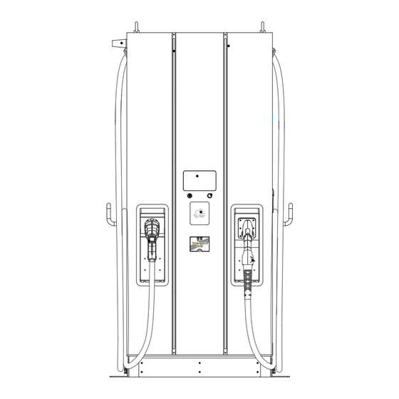
Basic User Interface
Antenna for Wi-Fi & 3G/4G
Location and function of the wireless communication antenna.
LED Indication
Explanation of LED indicators for charger status.
7" Information Screen
Components and features of the 7-inch display screen.
Right Button & Left Button
Functionality of the physical buttons on the charger.
Left DC Connector
Details about the left-side DC charging connector.
Right DC Connector
Details about the right-side DC charging connector.
Specification
Product Specification
Detailed technical parameters of the product.
DS180 Version Description
Version
Table listing different charger versions.
Left DC Connector
Type of DC connector on the left side.
AC Connector
Type of AC connector.
Right DC Connector
Type of DC connector on the right side.
Dimensions
Main Size of Charger:(Unit: mm)
Primary dimensions of the charger in millimeters.
Installation Instruction
3.1 Before Installation
Prerequisites and preparatory steps before installation.
WARNING: The product should be installed only by a licensed contractor...
Safety warning regarding qualified installation personnel.
WARNING: The product should be inspected by a qualified installer...
Installer responsibility for compliance with codes and standards.
Power feed must be 3 Phase Wye configuration...
Requirements for the AC power supply configuration.
In the installation of TN(-S) system...
Grounding and neutral connection details for TN(-S) systems.
In the installation of TT system...
Grounding and neutral connection details for TT systems.
The capacity of power supply should be higher than 196 kVA...
Minimum power supply capacity requirement.
The product should be installed in free air area and keep at least 30cm...
Clearance requirements for ventilation during installation.
Recommend to keep not less than 100cm...
Recommended clearance distances according to NEC standards.
NOTICE It is recommended to conduct WI-Fi and 3G/4G signal strength...
Recommendation for checking network signal strength during installation.
Contractor Safety guide
Introduction
Overview of the contractor safety guide's purpose.
In particular, employees should:
Specific safety responsibilities for employees.
Working at height
Avoid working at height by using alternative tools...
Preference for alternative methods over working at height.
It is strongly recommended to build suitable scaffolding...
Recommendation for using scaffolding or work platforms.
Provide fall arrest systems for workers if it is impracticable...
Requirement for fall arrest systems.
Secure all materials and tools to prevent them falling from height
Safety measure for securing items at height.
Lifting operations
Have lifting gear and apparatus regularly inspected...
Requirement for inspecting lifting equipment.
Isolate and cordon off lifting areas...
Procedure for securing lifting zones.
Ensure that lifting routes do not cross buildings or people...
Guidelines for safe lifting routes.
Do not exceed safe working load limits
Caution regarding lifting equipment load limits.
For on-site workers
Plan all work
Importance of work planning for on-site personnel.
Turn off power (work with live parts de-energized...
Procedure for de-energizing equipment before work.
LOTO (Lock Out, Tag Out)
Explanation of the Lockout/Tagout procedure.
Live electrical work permit (input terminals with HV...
Requirement for permits for live electrical work.
Use personal protective equipment (PPE)
Mandatory use of personal protective equipment.
Safe workplace conditions and space
Ensuring a safe working environment.
Adhere to other occupational health, safety and security codes...
Compliance with additional safety codes and standards.
Reference standards
Adhere to the following codes:
Specific safety codes to be followed.
Grounding and Safety Requirement
The product must be connected to a grounded, metal, permanent wiring system.
Requirement for a grounded wiring system.
Ensure no power is connected at all times when installing, servicing, or maintaining the charger.
Safety instruction to disconnect power during maintenance.
Use appropriate protection when connecting to main power distribution network.
Guidance on using protective measures for power connections.
Use appropriate tools for each task.
Importance of using correct tools for tasks.
CAUTION: The disconnect switch for each ungrounded conductor of AC input shall be provided by installation contractor or technician...
Caution regarding AC input disconnect switch requirements.
CAUTION: A cord extension set or second cable assembly shall not be used...
Caution against using extension cords for EVSE connection.
Service Wiring
Ground Connection
Procedure for establishing a proper ground connection.
480Vac Three-Phase(Line to Line)
Wiring diagram for 480Vac three-phase connection.
CAUTION! This is feed from Wye-connection power grid...
Caution regarding Wye-connection power grid and earth ground.
DANGERS Be Aware of High Voltage!
Warning about the presence of high voltage.
WARNING! Earth Connection is Essential!
Emphasis on the importance of earth connection.
Install Sensor Board for Safely Shutting Down
1. Introduction:
Purpose and function of the sensor board.
Sensor Board
Diagram labeling the sensor board component.
Circuit Breaker
Diagram labeling the circuit breaker.
2. Function Block Diagram:
Block diagram illustrating sensor board functionality.
Connecting Sensor Board:
4. Sensor Board Functions:
Explanation of how the sensor board functions.
a) When either door sensor or tilt sensor been trigger...
Functionality related to door/tilt sensor triggers.
b) When upstream circuit breaker been cut off...
Consequences of upstream circuit breaker being cut off.
c) This board has self-test button which is able to test if it functions properly...
Details on the sensor board's self-test capability.
Upstream circuit breaker selection and aux power preparation:
Below are reference SOR reference models from ABB:
Examples of SOR models from ABB.
NOTICE For the parts of SOR, maximum 277Vac withstand voltage is required.
Notice regarding voltage withstand for SOR components.
Wires Spec Selection:
Control Circuit
Diagram illustrating the control circuit wiring.
Unpack the charger
NOTICE The delivery truck unloads the pallet carrying the charger...
Notice regarding responsibility for charger movement after delivery.
If the TiltWatch indicator is red (tilted over 80°)
Procedure to follow if the TiltWatch indicator is red.
WARNING! Charger weight might be 470 kg.
Warning about the charger's weight during unpacking.
Or use a forklift to move the EVSE.
Step 1. Please remove the front and rear bottom trim panels first.
Step 1 of forklift moving: remove trim panels.
Step 2. Use a forklift to raise the EVSE.
Step 2 of forklift moving: raise the EVSE.
Recommended Tools for Installation and Inspection
Recommended Tools for Installation
Tools required for the installation process.
Installation Procedure
Required space for placing and maintaining
Specifications for the space needed for installation and maintenance.
Build Concrete Base
STEP 1.
First step in building the concrete base.
STEP 2.
Extend 3 phase 5 wires AC input cables...
Procedure for extending AC input cables and terminals.
METHOD 2.
If use L brackets to fix charger, secure L brackets on the cement base by 6 PCS M12 expansion bolts.
Procedure for fixing the charger with L brackets and expansion bolts.
Installing Cables
*Cable gland plate is adapted for the cable with diameter Ø42mm...
Information about the cable gland plate compatibility.
STEP 4. Wiring installation of L1, L2 and L3 of 3 Line wires...
A breaker with 30mA RCD-Type A is recommended.
Recommendation for a specific type of breaker.
STEP 5. Do inspection as section 3.7.1 to 3.7.3.
Not following installation instruction will cause charger damage.
Warning about consequences of incorrect installation.
Screw Torque Requirement Table
Screw in Metric
Torque requirements for metric screws.
Screw in Imperial
Torque requirements for imperial screws.
Installation Inspection & Commissioning
Environmental Check
Checks related to the environmental conditions of the installation site.
External Infrastructure Readiness & Check
Verification of external infrastructure required for operation.
EVSE Check - Static (Non-Powered)
Outlook
Visual inspection of the EVSE's exterior condition.
Labeling & Warning Signs
Verification of all labels and warning signs.
Robustness of Input Wirings & connection
Assessment of input wiring connections' integrity.
EVSE Check - Power On
WARNING! Improper connection of the EVSE grounding conductor...
Critical warning about improper grounding during power-on.
Power On
Verification of the charger powering on.
Screen On
Verification of the display screen functioning.
Acoustic Noise
Checking for any unusual operational noise.
Screen Display & Function
Verification of screen display and interactivity.
Time Display Correctly
Checking if the displayed time is accurate.
Network Connection Quality
Assessment of network connectivity status and quality.
Cooling Fans Operation & Noise
Checking the operation and noise level of cooling fans.
Led Status Indication
Verification of LED status indicators.
EVSE Setting
Checking the configured settings of the EVSE.
Function of Engineer Mode
Verifying the functionality of the engineer mode.
Version of H.W. & F.W.
Checking hardware and firmware versions.
Remote Control & Monitoring
Verification of remote control and monitoring capabilities.
Backend Server Connection
Checking the connection status to the backend server.
Network Connection & Quality
Verifying network connection status and quality.
EVSE Check - Charging
User Authorization -RFID
Checking RFID-based user authorization.
User Authorization -QR Code
Checking QR code-based user authorization.
User Authorization -Others.
Checking other user authorization methods.
Waiting Time of Connection Check
Measuring connection establishment time.
Reading of Each Display Item
Verifying all displayed information on the screen.
Full Charge Test
Performing a test to confirm full charge capability.
Function of Electronic Lock
Checking the operation of the electronic lock mechanism.
Reading of Engineer Mode
Accessing and verifying engineer mode data.
Airflow & Noise of Cooling Fan
Checking cooling fan airflow and noise levels.
Charging Record ( log ) Upload
Verifying the upload functionality of charging records.
Remote Control & Monitoring
Confirming remote control and monitoring functions.
EVSE Check -System Power Button
Emergency Stop Button & Recovery
Testing the emergency stop button and recovery function.
Tilt sensor and Door open sensor trigger & Recovery
Testing tilt and door open sensors and their recovery.
Network Setting
Wi-Fi Network Setting
Steps for setting up the Wi-Fi connection.
Laptop with RJ45 interface.
Requirement for a laptop with an RJ45 port.
Connect RJ45 cable from Laptop to charger's RJ45 port.
Instruction for connecting the laptop to the charger via RJ45.
Setup parameters in the Webservice.
Procedure for configuring parameters through the webservice.
Input RJ45 connector port is for engineer use for maintance.
Information on the purpose of the RJ45 connector port.
Use the following IP address:
Instructions for setting a static IP address.
Step 1.
Step 1 for Wi-Fi network configuration.
Step 2.
Step 2 for accessing the charger's web page.
Step 3.
Step 3 for navigating to the network settings.
Step 4. Select Wi-Fi Module
Wi-Fi Setting
Table of Wi-Fi settings and their descriptions.
WARNING: Due to the different environmental conditions...
Warning regarding network signal strength tests.
3G/4G Setting
SIM Card Installation
Instructions for installing the SIM card for 3G/4G connectivity.
Step 1. Pull out the first tray from the CSU box.
Step 1 of SIM card installation: accessing the tray.
Step 2. Insert 3G/4G Micro SIM Card in the tray...
Step 2 of SIM card installation: inserting the SIM card correctly.
Setting and Enable 3G/4G Module.
Step 1. Please contact your SIM provider to get the APN, PPP ID and password.
Step 1: Obtaining necessary SIM card information.
Step 2. SET -> Network.
Step 2 for navigating to network settings.
Step 3. Network -> 3G/4G Module to fill corresponding information...
Step 3: Entering 3G/4G module configuration details.
3G/4G setting
Table of 3G/4G settings and their descriptions.
Time setting
Automatic setting : The time will be adjusted automatically when the charger connects to internet.
Automatic time synchronization via internet connection.
Time server :
List of available time servers.
Manual setting :
Procedure for manually setting the charger's time.
Step 1.
Step 1 for manual time setting: connecting laptop.
Step 2. Before opening web browser, please enter network setting...
Step 2 for manual time setting: configuring IP address.
Step 3. Open web service browser, type the IP address of charger...
Step 3 for manual time setting: accessing charger's web page.
Operation Process
Operating Sequence
The sequence of operations during charging.
System Initialization
The initial startup process of the charger.
User Authorization
Steps for user authentication before charging.
Plug in DC Charging Connector
Action of connecting the charging cable to the EV.
Preparing for Charging
Stage where the charger prepares for the charging session.
In Charging
The active charging phase.
Charging Terminated
Process of ending a charging session.
Status Messages
Information displayed regarding charger status.
Operating Procedure
Detailed steps for operating the charger.
System Initialization
Detailed steps for the charger's system initialization.
User Authorization
Use your RFID card or mobile app to authorize the use of the EVSE.
Methods for authorizing EVSE usage.
User authorization Method: RFID, QR code and mobile APP.
Available user authorization methods.
Plug in Charging Connector
It will normally take less than 10 seconds to start the process after completing the physical connection...
Timeframe for the charging process to start after connection.
Prepare for Charging
Connector Select Button
Button used to select the charging connector.
Press right button to select the charger connector that the user would like to use.
Instruction for selecting the desired charging connector.
EV battery SOC
Display of the EV's State of Charge.
Charging information area
Section displaying charging progress details.
Charging duration
Display of the charging session's duration.
Charging power
Display of the current charging power.
Energy
Display of the total energy delivered.
Charging Terminated
Unplug the charging connector from charging inlet of the EV and return the charging connector to charging cable holder.
Action to unplug the connector and return it to the holder.
Status Messages
When problems occur with this charger or the charging process a status code will display on screen as below illustrated.
Display of status codes for errors or problems.
Troubleshooting
Please follow the instruction in the table when errors occur during the charging process.
Instruction to use the troubleshooting table for errors.
Or please connect the EVSE to the Internet and then contact the EVSE provider for further instructions.
Contacting the provider via internet for support.
Please provide the EVSE information including serial number, model name, status code, failure behavior and time, and also connect the EVSE to the Internet for remote diagnostics and upgrading.
Information required for remote diagnostics and support.
If an emergency occurs push the Emergency Stop Button to stop charging immediately.
Action to take in case of an emergency.
Troubleshooting Guide for End User
Troubleshooting steps specifically for end-users.
When charging fault occurs, user may eliminate fault status by following steps.
User-guided steps to resolve charging faults.
Black screen
Troubleshooting for a blank or black display screen.
Stuck on boot or service screen
Troubleshooting for a frozen or unresponsive screen.
Card tapping or QR code scanning failed
Troubleshooting for failed user authentication via card or QR.
Indication page returns from cable plugging to selection
Troubleshooting for incorrect screen progression after plugging in.
Troubleshooting - No Status Code
Black screen
Troubleshooting for a black screen without status codes.
Stuck on boot or service screen
Troubleshooting for a frozen screen without status codes.
Card tapping or QR code scanning failed
Troubleshooting failed authentication without status codes.
Indication page returns from cable plugging to selection
Troubleshooting incorrect screen progression without status codes.
(011-XXX) Troubleshooting - Error Code
011-XXX contains charger's parts or connection fault message...
Explanation of 011-XXX error code types.
Troubleshooting - Warning Code Form
Status Code
Table of warning status codes.
Conditions
Conditions associated with warning codes.
Troubleshooting methods
Methods to resolve warning codes.
(013-XXX) Troubleshooting-Message Code from Charger
013-XXX contains setup, maintenance, or reference hint messages...
Explanation of 013-XXX charger message types.
(023-XXX) Troubleshooting - Message Code from EV
023-XXX contains messages from EV, it means communication or charging procedure error...
Explanation of 023-XXX EV message types.
1) Unplug the charging cable and wait for 5 more seconds.
Troubleshooting step: unplug and replug cable.
2) Unplug the charging cable, try with the other one or charger.
Troubleshooting step: try alternative cable or charger.
3) Unplug the charging cable, drive the EV away for few meters / feet and return...
Troubleshooting step: move EV and retry.
4) After unplugging the charging cable, check the EV whether charging mode and time limit have been enabled.
Troubleshooting step: check EV charging settings.
5) If the charging process cannot be started and EV meter or charging indicator shows abnormal status or error messages, please follow your EV user manual for troubleshooting.
Troubleshooting step: refer to EV manual for abnormal indicators.
6) After unplugging the charging cable, contact management staff to turn off restart the charger and try again.
Troubleshooting step: contact staff for charger restart.
7) If charging terminated but the charging cable cannot be unplugged, please follow the EV user manual, press release button...
Troubleshooting step: manual unlock for stuck cable.
Status Codes
Status Code
Identifier for each status code.
Description
Explanation of what each status code signifies.
Status Code
Status Code
Identifier for each status code.
Description
Explanation of what each status code signifies.
Maintenance
Before Maintenance
Prerequisites and safety measures before performing maintenance.
To meet NFPA-70E, OSHA 1910.333 and other Health/safety/security codes, please adhere to the notice and get the permit needed in advance as below:
Safety and permit requirements before maintenance.
1) Turn off power (Work de-energized whenever possible)
Step 1: De-energize the equipment before maintenance.
2) Lockout/Tagout (LOTO)
Step 2: Apply Lockout/Tagout procedures.
3) Live work permit (Input terminals with HV after door open)
Step 3: Obtain permit for live work on terminals.
4) Plan the Work/Permit To Work
Step 4: Plan the maintenance work and obtain permits.
5) Use Personal Protective Equipment (PPE)
Step 5: Use appropriate Personal Protective Equipment.
6) Safe workplace condition & space
Step 6: Ensure safe working conditions and space.
Maintance Check List
Checklist for maintenance tasks.
Please refer to Appendix for more details.
Reference to appendix for detailed maintenance checklist.
General Maintenance
General guidelines for routine maintenance of the charger.
Replacement Kits and Accessories
Replacement Kit List
List of items included in the replacement kit.
Limited Product Warranty
The warranty period of this charger is according to purchasing contract; two years typically.
Standard warranty period for the charger.
Any spare parts provided by supplier Technology and used as replacements for repair are covered by a five-year guarantee.
Warranty coverage for replacement spare parts.
Warranty Exclusions:
List of conditions not covered by the product warranty.
Damage or rendered non- functional as a result of power surges, lighting, earthquake, fire, flood, pest damage, abuse, accident, misuse, negligence or failure to maintain the product or other event beyond supplier 's reasonable control or not arising from normal operating condition.
Exclusion for damages from external events and lack of maintenance.
Damage as a result of modifications, alterations or disassembling which were not pre-authorized in writing by supplier.
Exclusion for unauthorized modifications or disassembly.
Damage due to the failure to observe the applicable safety regulations governing the proper use of the product.
Exclusion for damage due to non-compliance with safety regulations.
Installed or operated not in strict conformance with the documentation, including without limitation, not ensuring sufficient ventilation for the product as described in supplier installation instruction.
Exclusion for improper installation or operation, including ventilation.
If a defect in the product arises and valid claim is received within the warranty period, your sole and exclusive remedy will be for supplier, at its sole discretion and to extent permitted by law, to
Supplier's remedy options for valid warranty claims.
1. Repair the defect in the product at no charge, using new or refurbished parts.
Remedy option: Repairing the defective product.
2. Exchange the product with new or refurbished product that is functionally equivalent to the original product.
Remedy option: Exchanging the product.
Appendix 1 - Package list
Item
Identifier for each package item.
Description
Description of each package item.
No.
Number of units for each item.
Remark
Additional remarks on package items.
Appendix 3 - Preventive Maintenance Check List
No.
Item number in the maintenance checklist.
Item
The specific maintenance task or component.
Description
Detailed description of the maintenance task.
0.5 year
Maintenance interval for 0.5 years.
1st year
Maintenance interval for the 1st year.
2nd year
Maintenance interval for the 2nd year.
3rd year
Maintenance interval for the 3rd year.
4th year
Maintenance interval for the 4th year.
5th year
Maintenance interval for the 5th year.
Note:
Key to understanding maintenance symbols.
I: Inspection
Definition of 'I' symbol for inspection.
R: Replacement or refill
Definition of 'R' symbol for replacement/refill.
--: No maintenance needed
Definition of '--' symbol for no maintenance required.
Need help?
Do you have a question about the DC EVSE 180KW 300A and is the answer not in the manual?
Questions and answers