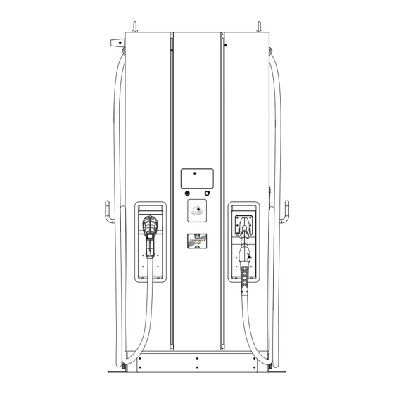
Blink DS Series User's Manual & Installation Instructions
Standalone fast charger
Hide thumbs
Also See for DS Series:
- User's manual & installation instructions (92 pages) ,
- User's manual & installation instructions (92 pages)
Table of Contents
Advertisement
Quick Links
Advertisement
Table of Contents


Need help?
Do you have a question about the DS Series and is the answer not in the manual?
Questions and answers