Table of Contents
Advertisement
Quick Links
Advertisement
Table of Contents

Subscribe to Our Youtube Channel
Related Manuals for Blink bluecorner PQ 150


Summary of Contents for Blink bluecorner PQ 150
- Page 1 USER MANUAL PQ 150 www.bluecorner.be...
-
Page 2: Safety Instructions
Installation Manual 1. GENERAL Read the instruction manual carefully before operating the unit. The instruction manual will help you to • use the product correctly • detect damage early, and prevent or repair damage • avoid failure and repair costs •... - Page 3 Installation Manual Repairs may not be carried out on the charging unit. Repairs may only be carried out by the manufacturer (replacement of the charging unit)! Do not make any unauthorized modifications to the charging unit! Contacts must not be oiled, greased or treated with contact spray! Do not remove labels such as the rating plate, warning notices, current limit marks or display symbols! Never disconnect the Connector System while charging is in progress! Before stopping the charging process, first unplug the charging connector from the vehicle and then unplug the grid connector.
-
Page 4: Intended Use
Installation Manual When removing the cable from the socket pull on the Connector System, never the cable! Protect the charging unit and the charging cable from mechanical damage (running over, pinching or kinking) and the electrical contact area from heat sources, dirt and water! Note that the Smart Attachments must be fitted with the IP 24 protective cover supplied when not connected in order to provide a sufficient IP protection level. -
Page 5: Product Description
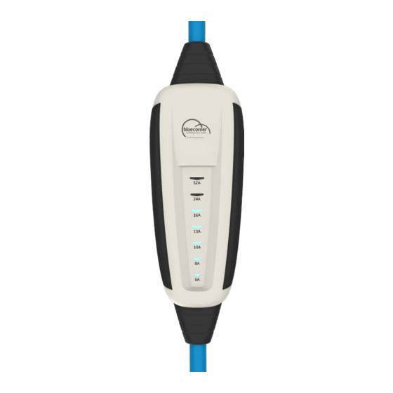
Installation Manual 4. PRODUCT DESCRIPTION The standard version of the PQ 150 charging unit consists of: A. the charging cable with the vehicle connector B. the electronics in a plastic housing (IC-CPD) including the residual current protection mechanism and energy meter with GSM and GNSS interface (GSM: EDGE, GPRS, 4G M1, 4G NB-IoT;... - Page 6 Installation Manual 5.1 CHARGING UNIT – PQ 150 1) Touch sensitive field 2) Display: Selectable maximum charging current 3) LED indicator: Selected charging current 5.2 PATENTED HIGH LEVEL SAFETY CONNECTOR SYSTEM WITH TEMPERATURE MONITORING AND HOT-UNPLUG PROTECTION Note: There are many different Smart Attachments available for all standard sockets and Type 2 connections. In the example above the Smart Attachment CEE 32A (standard in package) is shown.
- Page 7 Installation Manual 5.3 CHARGING YOUR ELECTRIC VEHICLE AT STANDARD POWER SUPPLY SOCKETS First, push the Smart Attachment onto the Connector Unit until you hear and feel it click into place. Then connect the Connector System to the power supply socket. The charging electronics will then initialize which is shown by an oscillating flashing signal of the LEDs.
-
Page 8: Connection Sequence
Installation Manual 5.4 INTERRUPTING THE CHARGING PROCESS The charging process should normally be stopped on the vehicle. Follow the instruction manual for your vehicle. The vehicle connector will then be unlocked and can be unplugged. Finally, disconnect the Connector System of the charging unit from the power socket. -
Page 9: Error Mode
Installation Manual 5.7 ERROR MODE Errors are indicated by flashing LEDs on the PQ 150 and the Connector Unit and through acoustic signals. The following signals are possible on PQ 150: • 5x flashing of all LEDs + short break (repeating) Indicates a general fault. -
Page 10: Integrated Functions
Installation Manual • LED 6A, 8A, 10A, 13A are illuminated permanently, all other LEDs are flashing Indicates an error detected by the overvoltage protection. One possible cause of an overvoltage is an incorrectly installed socket. Disconnect the charging unit from the power supply and check, with the help of an electrician if necessary, that the power supply line and socket are properly installed and free of faults. -
Page 11: Maintenance
Installation Manual 6. SMART ATTACHMENTS Only use Smart Attachments and accessories supplied with the charging unit or those approved by Blue Corner Take note of the maximum current that can be set for the specific Smart Attachment! In addition, PQ 150 features an automatic detection of the Smart Attachments. This ensures that the maximum permitted charging current for which the Smart Attachment has been approved for cannot be exceeded. -
Page 12: Technical Data
Installation Manual 10. TECHNICAL DATA Product name PQ 150 Nominal voltage 230V/400V 50Hz Nominal current Maximum charging power 22kW Residual current protection (AC) 30mA Residual current protection (DC) IP protection class IP67 Charge mode Mode 2 acc. to EN 62752 Mode 3 when using Smart Attachment Type 2 Ambient conditions -40°C …... -
Page 13: Declaration Of Conformity
For more information, contact your local authority, a local waste disposal service or the company from which you purchased the product. 12. DECLARATION OF CONFORMITY PQ150 (Charging unit for electric vehicles) Blue Corner / Blink Charging Posthoflei 3 bus 4 2600 Berchem Belgium +32 3 337 38 30 info@bluecorner.be... - Page 14 Installation Manual EN 55014-1 Electromagnetic compatibility - Requirements for household Appliances, electric tools and similar Apparatus (April 2017) - Part 1: Emission (CISPR 14-1:2016 + COR1:2016) EN 55014-2 Electromagnetic compatibility - Requirements for household Appliances, electric tools and similar Apparatus (April 2015) - Part 2: Immunity - Product family standard (CISPR 14-2:2015) EN 61000-3-2 Electromagnetic compatibility (EMC) - Part 3-2: Limits - Limits for harmonic current emission (IEC 61000-3-2:08/2014)
Need help?
Do you have a question about the bluecorner PQ 150 and is the answer not in the manual?
Questions and answers