Blink DS Series User's Manual & Installation Instructions
Standalone fast charger
Hide thumbs
Also See for DS Series:
- User's manual & installation instructions (92 pages) ,
- User's manual & installation instructions (92 pages)
Table of Contents
Advertisement
Quick Links
Advertisement
Table of Contents

Subscribe to Our Youtube Channel
Related Manuals for Blink DS Series


Summary of Contents for Blink DS Series
- Page 1 DS Series DC EVSE 120KW 300A Standalone Fast Charger User Manual & Installation Instructions Model Emergency Stop W84A99900253-RB1 COPYRIGHT © 2021 Reserves the right to make changes to this product without further notice. BlinkCharging.com (888) 998.2546 •...
-
Page 2: Table Of Contents
CONTENT Introductions ................1 Features ..................1 Applications ................1 1. Basic User Interface ..............2 ................3 ............3 2.2 DS120 Version Description ..........6 2.3 LED Indication and Operation Status ......... 7 2.4 Dimensions ..............8 2.5 Direction of cooling Airflow ..........8 3. - Page 3 7. Limited Product Warranty ............84 Appendix 1 - Package list ............86 Appendix 2 - Breaker Lock Installation ........87 Appendix 3 - Preventive Maintenance Check List ......88 BlinkCharging.com (888) 998.2546 •...
-
Page 4: Introductions
Introductions The Standalone DC Fast Charger is the top choice to power battery electric vehicles (BEV) and electric vehicles (PHEV). It is designed for quick charging in both public and private locations, such as retail and commercial parking spaces, fleet charging stations, highway service areas, workplace, residence, etc. -
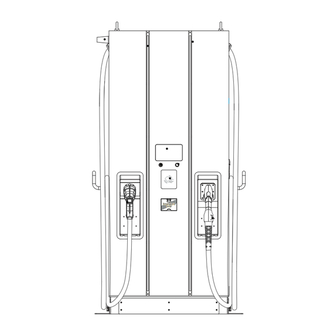
Page 5: Basic User Interface
1. Basic User Interface Antenna for Wi-Fi & 3G/4G LED Indication 7" Information Screen • Charging Status • Alarm information • User Authorization & Credit Card Payment System (Optional) Left DC Connector Emergency Stop Right DC Connector *The connectors installed on the EVSE may vary depending on the model(section 2.2) BlinkCharging.com... - Page 6 Model Name DSWX122 Series 3Φ480Vac (+10%,-15%) Voltage Rating 155A @277Vac Max. Input Current 183A@ 235Vac Electrical Distribution Power Grid System TN/TT INPUT Frequency 50/60Hz Max. Input Power 130kVA Power Factor > 0.99 > 94%, at optimize V/I point SCCR 35kA, optional for 65kA DC 150 ~ 950V (CCS) Output Voltage Range DC 150 ~ 500V (CHAdeMO)
- Page 7 < Standby Power 100W External Ethernet, Wi-Fi and 3G or 4G Communication Internal CAN Bus/ RS485 Input Protection OVP, OCP, OPP, UVP, RCD, SPD Output Protection OCP, OVP, LVP, OTP, IMD OTP, AC contactor detection, DC contactor detection, Fuse Internal Protection detection Load Management Via OCCP 1.6 JSON...
- Page 8 800x650x1900mm (32x26x75 Dimensions (WxDxH mm) inches ) <500kg (1102 lbs) with two Weight (typ.) Mechanical charging guns DC Charging Connector Refter to Chapter 2.2 Table Cooling Fan Cooling Ingression Protection NEMA 3R Anti-vandalism IK10, excluding LCD & RFID cover BlinkCharging.com (888) 998.2546 •...
-
Page 9: Ds120 Version Description
2.2 DS120 Version Description The DS120 series are available in different versions depending on the charging connectors, below table shows the available combinations, the corresponding position of charging connectors are indicated from left to right in the view of front charger. -
Page 10: Led Indication And Operation Status
2.3 LED Indication and Operation Status *Left LED for Left Connector, Right LED for Right Connector. Emergency Emergency Emergency Stop Stop Stop Standby Fault Charging Status Left Indicator Right Indicator Standby Green Green Fault Charging Blue Blue BlinkCharging.com (888) 998.2546 •... -
Page 11: Dimensions
2.4 Dimensions Main Size of Charger:(Unit: mm) 2.5 Direction of cooling Airflow Air In Air Out Emergency Stop BlinkCharging.com (888) 998.2546 •... -
Page 12: Installation Instruction
3. Installation Instruction 3.1 Before Installation • Read all the instructions before using and installing this product. • Do not use this product if power cable or charging cable have any damage. • Do not use this product if the enclosure or charging connector are broken or open or if there is damage. - Page 13 3.1.1 Contractor Safety guide Introduction • A safe work environment for everyone - participants, installation and demolition crews, contractors and subcontractors. Ultimately, it is the responsibility of contractors to ensure the safety and safe • work practices of their employees and subcontractors who may be working at the site on their behalf.
- Page 14 1.Requirements for workplace conditions • Set up suitable fencing to isolate the construction area from outside • Close and secure all entrances when the site is unattended • Hang warning notices nearby which show the following information: warning icon and phone number of person in charge •...
- Page 15 4.Protection against high temperatures on the worksite • Erect a sunshade or shed to shelter workers from the heat and sun • Set up cooling equipment, such as exhaust fans • Make water dispensers available • Provide suitable protective clothing such as hat, sunglasses and long sleeves to protect workers from heat stroke and UV rays 5.Inclement weather...
- Page 16 • protection equipment for workers • or reinforced plastic when carrying out electrical work • Assign assistants to provide support when working on ladders • Check all ladders for broken rungs or other defects before use and periodically • Fully open stepladders when in use •...
- Page 17 8.Lifting operations • Have lifting gear and apparatus regularly • Isolate and cordon off lifting areas to keep out non-construction personnel • Ensure that lifting routes do not cross buildings or people, and avoid collision with objects • Do not exceed safe working load limits 9.For on-site workers •...
-
Page 18: Grounding And Safety Requirement
3.2 Grounding and Safety Requirement • The product must be connected to a grounded, metal, permanent wiring system. Connections shall comply with all applicable electrical codes. Recommend the ground resistance be less than 10 Ω . • Ensure no power is connected at all times when installing, servicing, or maintaining the charger. - Page 19 3.2.1 Service Wiring • Ground Connection Always connect the Neutral at the service to Earth Ground. If ground is not provided by the electrical service then a grounding stake must be installed nearby. The grounding stake must be connected to the ground bar in the main breaker panel and Neutral connected to Ground at that point.
-
Page 20: Install Sensor Board For Safely Shutting Down
3.3 Install Sensor Board for Safely Shutting Down 1. Introduction: To prepare a control board which includes door sensor sensing function and tilt sensor, also dry contact points for extending wiring to upstream circuit breaker in order to cut off power immediately when sensors triggered. This board also has self-test button which uses to verify if it functions properly no matter in production line or in installation site or during regular maintenance service. - Page 21 3. Connecting Sensor Board: Connection from Connection from To upstream circuit 12Vdc Input from Door Sensor Charger backplane breaker Charger AUX power Module board and SOR unit Built-in self test button 4. Sensor Board Functions: a) When either door sensor or tilt sensor been trigger, it will send a voltage to trip off or open or cut off power of upstream circuit breaker, it is also knowns as “shunt release”...
- Page 22 NOTICE Once the power been from upstream circuit breaker, in order to get power back to charger ’ s auxiliary power supplies for maintenance purpose, please disable door limit switch before recovery circuit breaker. 5. Upstream circuit breaker selection and aux power preparation: Constructor or CPO is mandatory to select a circuit breaker which with “...
- Page 23 6. Wires Spec Selection: The wires from sensor board to upstream circuit breaker is recommended UL1015 22AWG 105 ° C 600V or relevant. Upstream Circuit Breaker Connector CNT3 UL1015, 22AWG Teisted Control Circuit Control Circuit BlinkCharging.com (888) 998.2546 •...
-
Page 24: Unpack The Charger
3.4 Unpack the charger • The product is direct current (DC) charger and the packing design passed the packaging simulation test. If the packaging damage caused by overturning, falling or external impact during transportation, it may cause the product damage or defects. If there is any serious damage to the packaging when receiving the goods, please notify the supplier about your findings. - Page 25 STEP 1. Remove the surrounding boards STEP 2. Remove the carton and packing cushion and film. BlinkCharging.com (888) 998.2546 •...
- Page 26 STEP 3. Remove these 6 pcs of fi xing M12 screws. STEP 4. To use lifting eye bolts to move the EVSE,please appply 6mm(1/4 inches ) diameter steel wire rope to the four eye bolts as following picture. BlinkCharging.com (888) 998.2546 •...
- Page 27 Or use a forklift to move the EVSE. Step 2. Use a forklift to raise the EVSE. (the fork must be opened to the maximum state) Step 1 Step 2 BlinkCharging.com (888) 998.2546 •...
-
Page 28: Recommended Tools For Installation And Inspection
3.5 Recommended Tools for Installation and Inspection 3.5.1 Recommended Tools for Installation Type Description Philips Screwdriver No. 2 and 3 Shifting Wrench Socket Screwdriver No. 8 and 10 and 17 and 19 Black / 15mm (0.6 ” ) Width Electrical Tape 3/0AWG (85.01mm²) for L1, L2, L3, N, and 6AWG (13.30mm²) for PE. - Page 29 3.5.2 Recommended Tools for Inspection & Commissioning Type Description EV or EV Simulator Meet CHAdeMO/CCS Standard Multi-meter 1000V Current Probe 200Amp RFID Authorized Card RFID No Valid Card Door Key Needle-Nose Plier Torque Meter screwdriver For Charger Configuration Laptop or PC & CAT6 cable If wireless router is used, please do not leave Wi-Fi, 3G/4G signal quality the router in metal box for better signal...
-
Page 30: Installation Procedure
3.6 Installation Procedure 3.6.1 Required space for placing and maintaining Required a space of 1600(62.99 ” ) x1600(62.99 ” ) mm.This space is calculated as follows: -Size Charge W x D x H:650(25.59 ” ) x 800(31.5 ” ) x 1900(74.8 ” ) mm. -Front side 850(33.46 ”... - Page 31 3.6.2 Build Concrete Base STEP 1. 1. Build 1090mm x 750mm x 200mm (42.91 ” x 29.53 ” x 7.87 ” ) concrete base on the level to stand charger in advance. 2. Implant AC input cable conduit less than Φ 102mm(eg.4 ” PVC conduit),and SFTP Ethernet cable conduit less than Φ...
- Page 32 1090.0(42.91") 4xM12 SCREW STICK 890.0(35.03") 690.0(27.17") 6XØ16MM(0.63") (L Bracket orifice) 100.0(3.94") Ø34MM(1.34") 200.0(7.87") 200.0(7.87") (For Ethernet Cable Conduit) 347.7(13.69) Ø102MM(4.02") 467.7(18.41") (For AC cable Conduit) STEP 2. • Extend 3 phase 5 wires AC input cables from conduit of concrete base, AC cables expose at least 3/0AWG (85.01mm²) for L1, L2, L3, N, and 6AWG (13.30mm²) for PE.
- Page 33 3.6.3 Two Methods of Fixing DS120 Charger METHOD 1. Lift the charger on concrete base, pull the input cable through bottom hole of charger; fasten 8 pcs of M12 screw nuts and 4 pcs M12 washers on 4 pcs of M12 screw of concrete base (2 nuts for each screw) to secure the chargers.
- Page 34 Step 3 BlinkCharging.com (888) 998.2546 •...
- Page 35 METHOD 2. If use L brackets to fix charger, secure L brackets on the cement base by 6 PCS M12 expansion bolts. BlinkCharging.com (888) 998.2546 •...
- Page 36 NOTE If remove the eye bolts on the top of the cabinet, must spread waterproof glue around the hole and assemble the waterproof plastic bolts(in the accessory pack). 3.6.4 Installing Cables M5x16 (4PCS) Cable Gland *Cable gland plate is adapted for the cable with diameter Ø42mm and optional for cables underground installation.
- Page 37 STEP 1. Open front door and disassembly the protection cover for wiring: STEP 2. Connect L1, L2, L3 and N of AC power to 4P terminal. Fasten each wire with proper screw and torque number- 180Kgf.cm/5-15 secs. Connect the PE wire (green with yellow) to Grounding position of Charger and torque number- 220Kgf.cm.
- Page 38 STEP 3. Pull AC power cables to power distribution box, connect the Protective Earth wire (Green/Yellow) to ground point of power distribution box. Neutral should be shorted with ground point to meet TN(-S) grounding system.Ethernet cable should be connected to charger RJ45 port (refer to pic. of section 4.1) STEP 4.
- Page 39 3.6.5 Screw Torque Requirement Table Screw in Metric Screw Steel Steel Steel Aluminum Aluminum Screw size type Inch-Lbs Kgf-Cm Kgf-Cm M2*0.4 Machine 3~4.77 3.5~5.5 0.34~0.54 3~4.5 0.34~0.44 M2.5*0.45 Machine 3~4.77 3.5~5.5 0.34~0.54 3~4.5 0.34~0.44 M3*0.5 Machine 5.5~9 6.5~10.5 0.64~1.04 5.2~8.4 0.51~0.82 M3.5*0.6 Machine 8.5~13...
-
Page 40: Installation Inspection & Commissioning
3.7 Installation Inspection & Commissioning 3.7.1 Environmental Check Item Status Remark Ambient Temperature Ambient Humidity Recommended but not Sunshade required. Recommended for better Rain Canopy charging experience and maintenance on rainy day. Installation Altitude <= 2000m (6560 ft) Air Circulation / Drafty Dust Level Anti-Vandalism Measures 3.7.2 External Infrastructure Readiness &... - Page 41 3.7.3 EVSE Check – Static (Non-Powered) Item Status Remark Outlook No dent, rust ,scratch Labeling & Warning Signs Package (Accessory) List Robustness of Input Wirings & Refer to section 3.6.5 Screw connection torque requirement table 3.7.4 EVSE Check - Power On WARNING! Improper connection of the EVSE grounding conductor can result in a risk of electric shock.
- Page 42 3.7.5 EVSE Check - Charging Item Status Remark User Authorization –RFID User Authorization –QR Code User Authorization –Others. Waiting Time of Connection Check Reading of Each Display Item Full Charge Test Temperature Reading Function of Electronic Lock Reading of Engineer Mode Airflow &...
-
Page 43: Network Setting
4. Network Setting 4.1 Wi-Fi Network Setting • Laptop with RJ45 interface. • Connect RJ45 cable from Laptop to charger ’ s RJ45 port. RJ45 • Setup parameters in the Webservice. • Input RJ45 connector port is for engineer use for maintance. Step 1. - Page 44 Step 4. 192.168.1.10 Select Wi-Fi Module Network Select Wi-Fi modes and fi ll in SSID and Password Network Status according to your application, if not required, just Ethernet keep default. WiFi 3G/4G Wi-Fi Setting Description 192.168.1.10 UPGRADE OTHER LANGUAGE Enable(station) or disable or Mode WiFI Module set as AP mode...
-
Page 45: 4G Setting
4.2 3G/4G Setting 4.2.1 SIM Card Installation Step 1. Pull out the first tray from the CSU box. And you can see the 4G/Wi-Fi module inside the cabinet. Step 2. Insert 3G/4G Micro SIM Card in the tray, ensure the gold contacts are facing down and the notch is located in the upper right corner. - Page 46 4.2.2 Setting and Enable 3G/4G Module. Step 1. 192.168.1.10 • Please contact your SIM provider to get the login https://192.168.1.10 APN, PPP ID and password. Account admin *Note: PPP ID and password maybe options depend on your SIM provider. Password 1231231238 •...
-
Page 47: Time Setting
4.3 Time setting Automatic setting : The time will be adjusted automatically when the charger connects to internet. Time server : time.windows.com • cn.ntp.org.cn • tock.stdtime.gov.tw • Note:Firewall and netw ork environment may influence the time server connection Manual setting : Step 1. - Page 48 Step 4. 192.168.1.10 SET -> Network. UPGRADE OTHER LANGUAGE System System Charging Network Backend Step 5. 192.168.1.10 System Click "System information". System Information Version Information Step 6. 192.168.1.10 Click system date time. System Click the calendar button on the right to set System Information System Information the current time.
-
Page 49: Operation Process
5. Operation Process 5.1 Operating Sequence • System Initialization • User Authorization • Plug in DC Charging Connector • Preparing for Charging • In Charging • Charging Terminated • Status Messages 5.2 Operating Procedure 5.2.1 System Initialization • When the charger is powered on, it start with the “ Charging Station ” Initializing page. - Page 50 Unit and currency if billing function is enabled • Ethernet Backend Status Connection Dis-Connection • Wi-Fi Status Connection Dis-Connection • 3G/4G Status Connection Dis-Connection • OCPP Backend Status Home page Connection Dis-Connection 5.2.2 User Authorization • After the system is initialized the screen will stay at Home page as below illustrated.
- Page 51 User authorizing User authorized. Authorization failed 5.2.3 Plug in Charging Connector • After authorization the screen will ask the user to plug the charging connector into the EV charging inlet as below illustrated. • Take the Charging connector from the charging cable holder and plug the connector into EV charging inlet.
- Page 52 5.2.4 Prepare for Charging • After authorization and plug-in process, the charger will start communicating with the vehicle and the screen will show the Preparing page as below illustrated. Information of Selected Charging Connector Connector Select Button Press right button to select the charger connector that the user would like to use.
- Page 53 • When the battery has been fully charged or reaches the limit of the setting it will stop charging automatically and go to the next process. Press right button to select the charger connector that the user would like to stop. •...
- Page 54 5.2.6 Charging Terminated • After charging is terminated the charger system will show the Charging Summary page as below illustrated and the charging connector will automatically unlock. • Unplug the charging connector from charging inlet of the EV and return the charging connector to charging cable holder.
-
Page 55: Troubleshooting
• Please follow the instruction in the table when errors occur during the charging process. • for further instructions. • Please provide the EVSE information including serial number, model name, status code, failure behavior and time, and also connect the EVSE to the Internet for remote diagnostics and upgrading. - Page 56 Conditions Troubleshooting guide 1. Please unplug the charging cable and try again. Indication page 2. Please check the EV charge port indicator or meter wheth - transfer from er the target charging limit has been done or terminated charging prepa - before default charging time.
- Page 57 5.3.2 Troubleshooting - No Status Code Conditions Troubleshooting guide 1. Incorrect input power or connection fault, please supply power correctly and reset the power. Black screen 2. Charger auxiliary power, display, or other faults. Please con - tact your dealer. 1.
- Page 58 Conditions Troubleshooting guide 1. Please unplug the charging cable and try again. 2. Please check the EV charge port indicator or meter whether Indication the target charging limit has been done or terminated before page transfer default charging time. * from charging 3.
- Page 59 5.3.4 Troubleshooting - Warning Code Form Status Conditions Troubleshooting methods Code 1. Charging can be enabled after electrical grid 012200 supply regularly. ↓ Abnormal input voltage 2. Please check the input power or turn off and 012214 restart the charger. 3.
- Page 60 5.3.5 (013-XXX) Troubleshooting-Message Code from Charger Code 013-XXX contains setup, maintenance, or reference hint messages, generally there is no impact on charging. Please charging with general process and contact your dealer. 5.3.6 (023-XXX) Troubleshooting - Message Code from EV 023-XXX contains messages from EV, it means communication or charging pro - cedure error, these errors cause charging or cable unplug cannot be proceeded.
- Page 61 Status Conditions Troubleshooting methods Code 1. Please unplug the charging cable, release EV side feedback code EV side charging limit, and try again. 23758 procedure error 2. Please follow step 1~7 for troubleshooting. 1. Charging cable is not locked by EV side, please unplug, and plug the charging cable 23809 completely with a “clicking”...
- Page 62 5.3.7 (033-XXX) Troubleshooting-Message Code from Charger Network 033-XXX contains messages from charger control server which is running intelligent remote control. Please follow the remote procedure or contact management staff to arrange for charging. Status Conditions Troubleshooting methods Code 1. Code scanning and app authorization is unavailable for the moment, please change to RFID or others authorization.
-
Page 63: Status Codes
5.4 Status Codes For latest status code, please visit our website. (V0.41) Status Code Description 011001 CHAdeMO output fuse blew 011002 CCS output fuse blew 011003 GB output fuse blew 011004 RCD/CCID self-test fail 011005 AC input contactor 1 welding 011006 AC input contactor 1 driving fault 011007... - Page 64 Status Code Description 011031 PSU module broken 011032 RCD/CCID module broken 011033 Maximum Output Current setup error 011034 Shutter fault 011035 Ble module broken 011036 Rotary switch fault 011037 CCS liquid chiller water level fault 011038 Chiller temperature sensor broken 011039 Reserved 011040...
- Page 65 Status Code Description 012222 System GB output OCP 012223 System ambient/inlet OTP 012224 System critical point OTP 012225 PSU ambient/inlet OTP 012226 PSU critical point OTP 012227 Aux. power module OTP 012228 Relay board/smart box OTP 012229 CHAdeMO connector OTP 012230 CCS connector OTP 012231...
- Page 66 Status Code Description 012254 Fail to create share memory 012255 CSU initialization failed 012256 AC Ground Fault 012257 MCU self-test Fault 012258 Relay self-test Fault 012259 CHAdeMO groundfault detection timeout (GFD) 012260 CCS groundfault detection timeout (GFD) 012261 GB groundfault detection timeout (GFD) 012262 System AC L1 output Circuit Short 012263...
- Page 67 Status Code Description 012286 Self test Failed due to communication of PSU failure 012287 Self test Failed due to Model name is none match 012288 CCS output UVP 012289 Chademo output UVP 012290 GBT output UVP 012291 Self test Failed due to communication of GBTboard failure 012292 Self test Failed due to communication of AC failure 012293...
- Page 68 Status Code Description 012318 Psu Pfc Eeprom Fault 012319 Psu Dcdc Over Voltage 012320 System CHAdeMO output UCP 012321 System CCS output UCP 012322 System GBT output UCP 012323 System Chiller output OTP 012324 Connector 1 detects abnormal voltage on the output line 012325 Connector 2 detects abnormal voltage on the output line 012326...
- Page 69 Status Code Description 013615 013616 013617 013618 013619 013620 013621 013622 disconnected from Internet through Ethernet 013623 disconnected from Internet through WiFi 013624 disconnected from Internet through 3G/4G 013625 disconnected from AP through WiFi 013626 disconnected from APN through 3G/4G 013627 WiFi disabled (separated charger only) 013628...
- Page 70 Status Code Description 023715 CHAdeMO: ev normal stop 023716 CHAdeMO: connector temperature sensor broken 023717 CHAdeMO: connector lock fail 023718 CHAdeMO: d1 on no receive 023719 CHAdeMO: bms k to j on timeout 023720 CHAdeMO: bms charge allow timeout 023721 CHAdeMO: wait groundfault timeout 023722 CHAdeMO: bms ev relay on timeout...
- Page 71 Status Code Description 023747 CCS_EVCC_EVErrorCode_FAILED_reserved_by_DIN_A 023748 CCS_EVCC_EVErrorCode_FAILED_reserved_by_DIN_B 023749 CCS_EVCC_EVErrorCode_FAILED_reserved_by_DIN_C 023750 CCS_EVCC_EVErrorCode_FAILED_reserved_by_ISO_1 023751 CCS_EVCC_EVErrorCode_FAILED_reserved_by_ISO_2 023752 CCS_EVCC_EVErrorCode_FAILED_reserved_by_ISO_3 023753 CCS_EVCC_EVErrorCode_FAILED_reserved_by_OEM_1 023754 CCS_EVCC_EVErrorCode_FAILED_reserved_by_OEM_2 023755 CCS_EVCC_EVErrorCode_FAILED_reserved_by_OEM_3 023756 CCS_EVCC_EVErrorCode_FAILED_reserved_by_OEM_4 023757 CCS_EVCC_EVErrorCode_FAILED_reserved_by_OEM_5 023758 CCS_SECC_ResponseCode_FAILED_SequenceError 023759 CCS_SECC_ResponseCode_FAILED_SignatureError 023760 CCS_SECC_ResponseCode_FAILED_UnknownSession 023761 CCS_SECC_ResponseCode_FAILED_ServiceIDInvalid 023762 CCS_SECC_ResponseCode_FAILED_Payment SelectionInvalid 023763 023764 CCS_SECC_ResponseCode_FAILED_ServiceSelectionInvalid 023765 023766 023767 023768...
- Page 72 Status Code Description 023779 CCS_SECC_ResponseCode_FAILED_PowerDeliveryNotApplied 023780 CCS_SECC_ResponseCode_FAILED_MeteringSignatureNotValid 023781 CCS_SECC_ResponseCode_FAILED_NoChargeServiceSelected 023782 CCS_SECC_ResponseCode_FAILED_ContactorError CCS_SECC_ResponseCode_FAILED_ 023783 023784 CCS_SECC_ResponseCode_FAILED_GAChargeStop 023785 CCS_SECC_ResponseCode_FAILED_AlignmentError 023786 CCS_SECC_ResponseCode_FAILED_ACDError 023787 CCS_SECC_ResponseCode_FAILED_AssociationError 023788 CCS_SECC_ResponseCode_FAILED_EVSEChargeAbort 023789 CCS_SECC_ResponseCode_FAILED_NoSupportedApp-Protocol 023790 CCS_SECC_ResponseCode_FAILED_ContractNotAccepted 023791 CCS_SECC_ResponseCode_FAILED_MOUnknown 023792 CCS_SECC_ResponseCode_FAILED_OEM_SubCA1_ 023793 CCS_SECC_ResponseCode_FAILED_OEM_SubCA2_ 023794 CCS_SECC_ResponseCode_FAILED_OEM_RootCA_ 023795 023796 CCS_SECC_ResponseCode_FAILED_MO_SubCA1_ 023797 CCS_SECC_ResponseCode_FAILED_MO_SubCA2_ 023798 CCS_SECC_ResponseCode_FAILED_MO_RootCA_ 023799...
- Page 73 Status Code Description CCS_SECC_ResponseCode_FAILED_CPS_RootCA_ 023803 023804 CCS_SECC_ResponseCode_FAILED_reserved_1 023805 CCS_SECC_ResponseCode_FAILED_reserved_2 023806 CCS_SECC_ResponseCode_FAILED_reserved_3 023807 CCS_SECC_ResponseCode_FAILED_reserved_4 023808 CCS_SECC_ResponseCode_FAILED_reserved_5 023809 CCS_SECC_TIMEOUT_SLAC_TT_EVSE_SLAC_init 023810 CCS_SECC_TIMEOUT_SLAC_TP_match_response 023811 CCS_SECC_TIMEOUT_CM_START_ATTEN_CHAR_IND 023812 CCS_SECC_TIMEOUT_SLAC_TT_EVSE_match_MNBC 023813 CCS_SECC_TIMEOUT_SLAC_TP_EVSE_avg_atten_calc 023814 CCS_SECC_TIMEOUT_SLAC_CM_ATTEN_CHAR_RSP CCS_SECC_TIMEOUT_SLAC_CM_VALIDATE_REQ_1ST__CM_SLAC_ 023815 MATCH_REQ 023816 CCS_SECC_TIMEOUT_SLAC_TT_EVSE_assoc_session 023817 CCS_SECC_TIMEOUT_SLAC_TT_EVSE_vald_toggle 023818 CCS_SECC_TIMEOUT_SLAC_CM_MNBC_SOUND_IND CCS_SECC_TIMEOUT_SLAC_CM_VALIDATE_REQ_2ND__CM_SLAC_ 023819 MATCH_REQ 023820 CCS_SECC_TIMEOUT_SLAC_reserved_3 023821 CCS_SECC_TIMEOUT_SLAC_reserved_4...
- Page 74 Status Code Description CCS_SECC_TIMEOUT_V2G_Msg_Performance_Time_ 023832 SupportedAppProtocolRes CCS_SECC_TIMEOUT_V2G_Msg_Performance_Time_ 023833 SessionSetupRes CCS_SECC_TIMEOUT_V2G_Msg_Performance_Time_ 023834 ServiceDiscoveryRes CCS_SECC_TIMEOUT_V2G_Msg_Performance_Time_ 023835 ServicePaymentSelectionRes CCS_SECC_TIMEOUT_V2G_Msg_Performance_Time_ 023836 ContractAuthenticationRes CCS_SECC_TIMEOUT_V2G_Msg_Performance_Time_ 023837 ChargeParameterDiscoveryRes CCS_SECC_TIMEOUT_V2G_Msg_Performance_Time_ 023838 PowerDeliveryRes CCS_SECC_TIMEOUT_V2G_Msg_Performance_Time_ 023839 CableCheckRes CCS_SECC_TIMEOUT_V2G_Msg_Performance_Time_ 023840 PreChargeRes CCS_SECC_TIMEOUT_V2G_Msg_Performance_Time_ 023841 CurrentDemandRes CCS_SECC_TIMEOUT_V2G_Msg_Performance_Time_ 023842 WeldingDetectionRes CCS_SECC_TIMEOUT_V2G_Msg_Performance_Time_ 023843 SessionStopRes 023844 CCS_SECC_TIMEOUT_V2G_Sequence_Time 023845 CCS_SECC_TIMEOUT_V2G_ReadyToCharge_Performance_Time...
- Page 75 Status Code Description 023853 CCS_SECC_TIMEOUT_V2G_reserved_4 023854 CCS_SECC_TIMEOUT_V2G_reserved_5 023855 CCS_CAN_TIMEOUT_TP_GET_EV_TARGET_INFO 023856 CCS_CAN_TIMEOUT_TT_GET_EV_TARGET_INFO 023857 CCS_CAN_TIMEOUT_TP_GET_EV_BATTERY_INFO 023858 CCS_CAN_TIMEOUT_TT_GET_EV_BATTERY_INFO 023859 CCS_CAN_TIMEOUT_TP_EV_STOP_EVENT 023860 CCS_CAN_TIMEOUT_TT_EV_STOP_EVENT 023861 CCS_CAN_TIMEOUT_TP_EVSE_STOP_EVENT 023862 CCS_CAN_TIMEOUT_TT_EVSE_STOP_EVENT 023863 CCS_CAN_TIMEOUT_TP_GET_MISC_INFO 023864 CCS_CAN_TIMEOUT_TT_GET_MISC_INFO 023865 CCS_CAN_TIMEOUT_TP_DOWNLOAD_REQUEST 023866 CCS_CAN_TIMEOUT_TT_DOWNLOAD_REQUEST 023867 CCS_CAN_TIMEOUT_TP_START_BLOCK_TRANSFER 023868 CCS_CAN_TIMEOUT_TT_START_BLOCK_TRANSFER 023869 CCS_CAN_TIMEOUT_TP_DATA_TRANSFER 023870 CCS_CAN_TIMEOUT_TT_DATA_TRANSFER 023871 CCS_CAN_TIMEOUT_TP_DOWNLOAD_FINISH 023872 CCS_CAN_TIMEOUT_TT_DOWNLOAD_FINISH...
- Page 76 Status Code Description 023885 CCS_SECC_ISO1_Msg_Decode_Error 023886 CCS_SECC_ISO1_Msg_Encode_Error 023887 CCS_SECC_ISO2_Msg_Decode_Error 023888 CCS_SECC_ISO2_Msg_Encode_Error 023889 CCS_SECC_CP_State_Error 023890 CCS_SECC_Unexpected_60V_Before_Charing_Error 023891 CCS_SECC_Not_Ready_For_Charging 023892 QCA7000 may not be installed, yet) 023893 CCS_SECC_FAIL_QCA7000_SETKEY 023894 Reserved 023895 Reserved 023896 Reserved 023897 Reserved 023898 Reserved 023899 Reserved 023900 GBT_LOS_CC1 023901 GBT_CONNECTOR_LOCK_FAIL 023902...
- Page 77 Status Code Description 023916 GBT_REQ_CURRENT_MORE_THAN_LIMIT 023917 GBT_OUTPUT_VOLTAGE_MORE_THAN_10_PERCENT 023918 GBT_OUTPUT_VOLTAGE_DIFF_BCS_5_PERCENT 023919 GBT_STOP_ADC_MORE_THAN_10V 023920 Reserved 023921 Reserved 023922 Reserved 023923 Reserved 023924 Reserved 023925 Reserved 023926 Reserved 023927 Reserved 023928 Reserved 023929 Reserved 023930 GBT_CEM_BHM_TIMEOUT 023931 GBT_CEM_BRM_TIMEOUT 023932 GBT_CEM_BCP_TIMEOUT 023933 GBT_CEM_BRO_TIMEOUT 023934 GBT_CEM_BCL_TIMEOUT 023935 GBT_CEM_BCS_TIMEOUT...
- Page 78 Status Code Description 023948 Reserved 023949 Reserved 023950 GBT_BST_SOC_GOAL 023951 GBT_BST_TOTAL_VOLTAGE_GOAL 023952 GBT_BST_CELL_VOLTAGE_GOAL 023953 GBT_BST_GET_CST 023954 GBT_BST_ISOLATION 023955 GBT_BST_OUTPUT_CONNECTOR_OTP 023956 GBT_BST_COMPONEN 023957 GBT_BST_CHARGE_CONNECTOR 023958 GBT_BST_OTP 023959 GBT_BST_OTHER 023960 GBT_BST_HIGH_V 023961 GBT_BST_CC2 023962 GBT_BST_CURRENT 023963 GBT_BST_VOLTAGE 023964 GBT_GET_BST_NO_REASON 023965 Reserved 023966 Reserved 023967 Reserved...
- Page 79 Status Code Description 023980 ERROR_CODE_CHADEMO_BMS_CHARGE_ALLOW_ERROR ERROR_CODE_CHADEMO_OUTPUT_VOLTAGE_MORE_THAN_10_ 023981 PERCENT 023982 ERROR_CODE_CHADEMO_ADC_LESS_THAN_10V 023983 STOP by EV with unknow reason 033900 disconnected from backend through Ethernet 033901 disconnected from backend through WiFi 033902 disconnected from backend through 3G/4G 033903 Remote start charging by backend 033904 Remote stop charging by backend 033905...
- Page 80 Status Code Description 042201 System L2 input OVP 042202 System L3 input OVP 042203 System L1 input UVP 042204 System L2 input UVP 042205 System L3 input UVP 042206 PSU L1 input OVP 042207 PSU L2 input OVP 042208 PSU L3 input OVP 042209 PSU L1 input UVP 042210...
- Page 81 Status Code Description 042252 Door open 042253 System fan decay 042254 Fail to create share memory 042255 CSU initialization failed 042257 MCU self-test Fault 042258 Relay self-test Fault 042262 System AC L1 output Circuit Short 042263 PSU Duplicate ID 042264 PSU Output Short Circuit 042265 PSU Discharge Abnormal...
- Page 82 Status Code Description 042291 Self test Failed due to communication of GBTboard failure 042292 Self test Failed due to communication of AC failure 042293 Self test Failed due to communication of Ledboard failure 042294 AC input ovp 042295 AC input uvp 042299 System AC L2 output OCP 042300...
- Page 83 Status Code Description 043612 043614 043615 043616 043617 043618 043619 043620 043621 043622 disconnected from Internet through Ethernet 043623 disconnected from Internet through WiFi 043624 disconnected from Internet through 3G/4G 043625 disconnected from AP through WiFi 043626 disconnected from APN through 3G/4G 043627 WiFi disabled (separated charger only) 043628...
-
Page 84: Maintenance
6. Maintenance 6.1 Before Maintenance To meet NFPA-70E, OSHA 1910.333 and other Health/safety/security codes, please adhere to the notice and get the permit needed in advance as below: 1) Turn off power (Work de-energized whenever possible) 2) Lockout/Tagout (LOTO) 3) Live work permit (Input terminals with HV after door open) 4) Plan the Work/Permit To Work 5) Use Personal Protective Equipment (PPE) 6) Safe workplace condition &... - Page 85 • When using the DC Fast Charger please handle properly. Do not strike or scrape the cabinet or screen. • If the enclosure or screen is broken, cracked, open or shows any other indication of damage then please contact the Standalone DC Fast Charger provider. WARNING: Danger of electrical shock or injury.
-
Page 86: Replacement Kits And Accessories
6.3 Replacement Kits and Accessories The DC EVSE offers the following replacement kits and accessories. Replacement Kit List 7-inch LCD 30kW DC PSU U-1K0100 MW Aux. Power HVG-150-12A MW Aux. Power HVG-240-24A Control & Supervisory Unit (CSU3.0) Surge Protection Device (SPD) DC Fan Air Filters RFID Readers... -
Page 87: Limited Product Warranty
7. Limited Product Warranty The warranty period of this charger is according to purchasing contract; two years typically. Any spare parts provided by supplier Technology and used as replacements for repair are covered by a five-year guarantee. Replacement and repair parts manufactured by alternative manufacturers to those on the maintenance parts are only allowed if authorized by supplier. - Page 88 Any remedy hardware product will be warranted for the remainder of the original warranty period or 90 days from delivery to the customer, whichever is longer. In order to receive the remedy set for above, you must contact supplier during the warranty period and provide the model number, series number, proof of purchase, and date of purchase.
-
Page 89: Appendix 1 - Package List
Appendix 1 - Package list Item Description Remark EVSE User manual EVSE Approved certificate OQC Report RFID Card Door Key Base cover M4x8 screw Breaker Lock 10 Waterproof Plastic Bolts Charging Gun Labels Cable Management Optional BlinkCharging.com (888) 998.2546 •... -
Page 90: Appendix 2 - Breaker Lock Installation
Appendix 2 - Breaker Lock Installation BlinkCharging.com (888) 998.2546 •... -
Page 91: Appendix 3 - Preventive Maintenance Check List
Appendix 3 - Preventive Maintenance Check List Item Description year year year year year year Preventive maintenance Appearance Appearance visual inspection inspection Fan clean and spinning 3 System fan smoothly check Air filter, air inlet and outlet 4 Air filter clean 5 Charging cable Appearance clean 6 PCBA... - Page 92 Manufacturer Contact Info Sticker BlinkCharging.com (888) 998.2546 •...
Need help?
Do you have a question about the DS Series and is the answer not in the manual?
Questions and answers