Sign In
Upload
Download
Table of Contents
Contents
Add to my manuals
Delete from my manuals
Share
URL of this page:
HTML Link:
Bookmark this page
Add
Manual will be automatically added to "My Manuals"
Print this page
×
Bookmark added
×
Added to my manuals
Manuals
Brands
FLENDER Manuals
Industrial Equipment
FLUDEX FAD
Assembly and operating instructions manual
FLENDER FLUDEX FAD Assembly And Operating Instructions Manual
Hide thumbs
1
2
Table Of Contents
3
4
5
6
7
8
9
10
11
12
13
14
15
16
17
18
19
20
21
22
23
24
25
26
27
28
29
30
31
32
33
34
35
36
37
38
39
40
41
42
43
44
45
46
47
48
49
50
51
52
53
54
55
56
57
58
59
60
61
62
63
64
65
66
67
68
69
70
71
72
73
74
75
76
77
78
79
80
81
82
83
84
85
86
page
of
86
Go
/
86
Contents
Table of Contents
Bookmarks
Table of Contents
Table of Contents
Introduction
Legal Information
About These Instructions
Text Attributes
Copyright
Safety Information
General Information
Table 2-1 General Warnings
Intended Use
Safety Information for a Coupling When Used in Potentially Explosive Atmospheres
Marking
Conditions of Use
Table 2-2 Temperature Classes (X) for Explosive Atmospheres as a Result of Gases, Vapours or
Table 2-3 Maximum Surface Temperature (X) for a Potentially Explosive Atmosphere as a Result of
General Warning Notices
Description
Design of the Couplings
Figure 3-1 General Description of FA Series
Coupling Versions
Figure 3-2 Coupling Model
Application Planning
Transport of the Coupling
Storage of the Coupling
Figure 4-1 Transport Symbols
Table 4-1 Types of Preservative Agents for Long-Term Storage
Assembly
Preparatory Work
Mill the Finished Bore
Table 5-1 Recommended Assigned Fits for Bores with Parallel Key Connection
Figure 5-1 Tolerances for Finished Bore
Mill the Parallel Keyway
Machining an Axial Locking Mechanism
Table 5-2 Maximum Bores for N-EUPEX Add-On Coupling
Table 5-3 Position of the Parallel Keyway
Figure 5-2 Diameter and Axial Position of the Threaded Hole in the Hub
Table 5-4 Diameter and Axial Position of the Threaded Hole, Tightening Torque
Table 5-5 Position of the Threaded Hole with Respect to the Parallel Keyway
Balancing the Coupling
Figure 5-3 Position of the Balancing Bore for Single-Plane Balancing
Figure 5-4 Position of the Balancing Bore for Two-Plane Balancing
Mounting the Coupling
Mounting the FLUDEX Coupling
Figure 5-5 Mounting the Coupling Parts
Mounting the N-EUPEX Coupling
Aligning the Coupling
Purpose of Alignment
Possible Misalignment
Axial Misalignment
Angular Misalignment
Radial Misalignment
Figure 5-6 Possible Misalignments
Filling the Gear Unit with Operating Fluid
Operating Fluid, Oil
Filling Quantity
Procedure
Figure 5-7 Filling the Coupling
Housing
Commissioning
Operation
Normal Operation of the Coupling
Fault - Causes and Correction
Procedure in the Event of Faults
Identifying the Fault Cause
Possible Faults
Possible Causes
Unsuitable Coupling
Table 7-1 Table of Faults
Assembly-Related Causes
Maintenance-Related Causes
Specific Assembly-Related and Maintenance-Related Causes
Resolving Faults
Replacing Wearing Parts
Correcting the Changed Alignment
Replacing the Fusible Safety Plug
Maintenance
Maintenance Intervals
N-EUPEX Add-On Coupling
FLUDEX Coupling
Maximum Permissible Torsional Backlash
Table 8-1 Maintenance Intervals
Table 8-2 Operating Temperatures, Operating Hours and Years of Use
Replacing the Flexible Elements
Table 8-3 Maximum Permissible Torsional Backlash
Figure 8-1 Markings for Calculating the Torsional Backlash
Disassembling the FLUDEX Coupling
Disassembling Sizes 222 to 342
Figure 8-2 Pull Nut and Spindle
Disassembling Sizes 395 to 590
Figure 8-3 Disassembling Sizes 222 to 342
Disassembling N-EUPEX Add-On Coupling
Dismantling the FLUDEX Coupling
Figure 8-4 Dismantling the FLUDEX Coupling
Reassembling the FLUDEX Coupling
Service and Support
Contact
Disposal
Replacement Parts
Ordering Replacement Parts
Spare Parts Drawing and Spare Parts List
Types FAO, FAK, FAD, FAE, FAM, FADB, FADS
Types FAR
Technical Specifications
Filling Quantity
Filling Quantity for FLUDEX Couplings FA
Table A-1: Filling Quantity for FLUDEX Couplings "FA.." Size 222
Filling Quantity for FLUDEX Couplings "FA
Table A-2 Filling Quantity for FLUDEX Couplings "FA
Table A-3 Filling Quantity for FLUDEX Couplings "FA
Filling Quantity for FLUDEX Couplings "FA
Table A-4 Filling Quantity for FLUDEX Couplings "FA
Filling Quantity for FLUDEX Couplings "FA
Table A-5 Filling Quantity for FLUDEX Couplings "FA
Filling Quantity for FLUDEX Couplings "FA.." Size 516
Table A-6 Filling Quantity for FLUDEX Couplings "FA
Filling Quantity for FLUDEX Couplings "FA.." Size 590
Table A-7 Filling Quantity for FLUDEX Couplings "FA
Bearing Lubrication for Rolling-Contact Bearing, Type FAR
Shaft Misalignment Values During Operation
Table A-8 Oil Quantities for Lubricating Rolling-Contact Bearing in the Belt Pulleys
Tightening Torques and Widths A/F
Tightening Torques for Parts 13, 22, 23, 24 and 103
Table A-9 Maximum Permissible Shaft Misalignment Values During Operation
Tightening Torques for Parts 110, 142, 163, 121, 130, 131 and 153
Tightening Torques for Retaining Screws
Tightening Procedure
Table A-10 Tightening Torques for Parts 13, 22, 23, 24 and 103
Table A-11 Tightening Torques for Parts 110, 142, 163, 121, 130, 131 and 153
Table A-12 Tightening Torques for Retaining Screws
Flexible Elements (12)
Use and Storage of Flexible Elements (12)
N-EUPEX Flexible Elements (12)
Table A-13 Tightening Procedure
Declaration of Conformity
EU Declaration of Conformity
Advertisement
Quick Links
Download this manual
FLUDEX
Assembly and operating instructions M4600-01en
Edition 09/2022
FAO, FAD, FAE, FAM, FADB, FADS, FAK, FAKB, FAR
Table of
Contents
Previous
Page
Next
Page
1
2
3
4
5
Advertisement
Table of Contents
Need help?
Do you have a question about the FLUDEX FAD and is the answer not in the manual?
Ask a question
Questions and answers
Related Manuals for FLENDER FLUDEX FAD
Industrial Equipment FLENDER FLUDEX Assembly And Operating Instructions Manual
(86 pages)
Industrial Equipment FLENDER FLUDEX FAO Assembly And Operating Instructions Manual
(86 pages)
Industrial Equipment FLENDER FLUDEX FGO Assembly And Operating Instructions Manual
(86 pages)
Industrial Equipment FLENDER BNN Operating Instructions Manual
Flender couplings (66 pages)
Industrial Equipment FLENDER BIPEX-S Operating Instructions Manual
Flender couplings (66 pages)
Industrial Equipment FLENDER BKK Operating Instructions Manual
Flender couplings (66 pages)
Industrial Equipment FLENDER H Series Operating Instructions Manual
Gear unit (110 pages)
Industrial Equipment FLENDER REDUREX Operating Instructions Manual
Gear units 5200en (128 pages)
Industrial Equipment FLENDER ARPEX ARS-6 Operating Instructions Manual
Couplings (36 pages)
Industrial Equipment FLENDER ZAPEX Operating Instructions Manual
Couplings (16 pages)
Industrial Equipment FLENDER SECUREX T 3950de Assembly And Operating Instructions Manual
Torque limiter (32 pages)
Industrial Equipment FLENDER ZAPEX-ZI Manual
Gear couplings acc. to international standards, grease lubrication, o-ring seal (28 pages)
Industrial Equipment FLENDER ELPEX-B EBWT Series Manual
Highly flexible couplings (16 pages)
Industrial Equipment FLENDER N-EUPEX Manual
Flexible couplings (40 pages)
Industrial Equipment FLENDER ELPEX-B EBWT 105 Manual
Highly flexible couplings (20 pages)
Industrial Equipment FLENDER H V Series Assembly And Operating Instructions Manual
Gear units (164 pages)
Summarization of Contents
1 Introduction
1.1 Legal information
Provides essential legal and regulatory information regarding the product and its use.
1.2 About these instructions
Explains the purpose and scope of the assembly and operating instructions.
1.3 Text attributes
Details text formatting, warning symbols, and their meanings for clarity.
1.4 Copyright
Outlines copyright ownership and usage restrictions for the document.
2 Safety information
2.1 General information
Covers general safety principles, state of the art, and symbol explanations.
2.2 Intended use
Specifies the correct and incorrect uses of Flender products to ensure safety.
2.3 Safety information for a coupling when used in potentially explosive atmospheres
Provides critical safety guidelines for operating in environments with explosive atmospheres.
3 Description
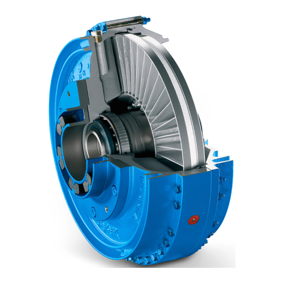
3.1 Design of the couplings
Illustrates and explains the components and construction of the FLUDEX coupling types.
3.2 Coupling versions
Presents different models and configurations of the FLUDEX coupling.
4 Application planning
4.1 Transport of the coupling
Details safe procedures and symbols for transporting the coupling components.
4.2 Storage of the coupling
Provides guidelines for proper storage to maintain coupling integrity and prevent damage.
5 Assembly
5.1 Preparatory work
Outlines necessary steps before mounting, like bore machining and keyway preparation.
5.2 Mounting the coupling
Describes the correct procedures for fitting the FLUDEX and N-EUPEX couplings.
5.3 Aligning the coupling
Explains the importance of alignment and methods to achieve it.
7 Operation
7.1 Normal operation of the coupling
Describes the expected behavior of the coupling during normal running conditions.
7.2 Fault - causes and correction
Guides users on identifying and rectifying common faults, issues, and their causes.
8 Maintenance
8.1 Maintenance intervals
Specifies recommended intervals for routine maintenance tasks for optimal performance.
8.2 Maximum permissible torsional backlash
Defines acceptable limits for torsional backlash to ensure proper function.
8.3 Replacing the flexible elements
Details the procedure for replacing worn or damaged flexible elements.
8.4 Disassembling the FLUDEX coupling
Provides step-by-step instructions for safely taking apart the FLUDEX coupling.
8.5 Disassembling N-EUPEX add-on coupling
Outlines the process for disassembling the N-EUPEX add-on coupling.
8.6 Dismantling the FLUDEX coupling
Describes how to dismantle the FLUDEX coupling, with specific notes for FAR type.
8.7 Reassembling the FLUDEX coupling
Guides users on the correct procedure for reassembling the FLUDEX coupling.
6 Commissioning
Testing before commissioning
Lists essential checks and tests to perform before the coupling is put into operation.
10 Disposal
Disposal of the coupling
Instructs on the proper disposal or recycling of coupling parts according to regulations.
11 Replacement parts
11.1 Ordering replacement parts
Explains how to order necessary replacement parts and the information required.
11.2 Spare parts drawing and spare parts list
Provides detailed diagrams and lists of all available spare parts for the coupling.
A Technical specifications
A.1 Filling quantity
Lists oil filling quantities for various FLUDEX coupling sizes and operating speeds.
A.2 Bearing lubrication for rolling-contact bearing, type FAR
Specifies the type of oil and quantities for lubricating rolling-contact bearings in FAR type.
A.3 Shaft misalignment values during operation
Defines the maximum permissible shaft misalignment values during the coupling's operation.
A.4 Tightening torques and widths A/F
Provides torque specifications and wrench sizes for various screws and bolts.
A.5 Tightening procedure
Details the correct sequence and methods for tightening components.
A.6 Flexible elements (12)
Covers information on the use, storage, and types of flexible elements.
B Declaration of conformity
B.1 EU Declaration of Conformity
Contains the official EU Declaration of Conformity for the FLUDEX coupling.
Table of Contents
Print
Rename the bookmark
Delete bookmark?
Delete from my manuals?
Login
Sign In
OR
Sign in with Facebook
Sign in with Google
Upload manual
Upload from disk
Upload from URL
Need help?
Do you have a question about the FLUDEX FAD and is the answer not in the manual?
Questions and answers