
Related Manuals for Flexim FLUXUS G608


Summarization of Contents
1 Introduction
1.1 Regarding this Manual
Information about the manual's purpose, content, and usage guidelines for the ultrasonic flowmeter.
1.2 Safety Instructions
Crucial safety instructions and warnings for operating the flowmeter, including specific directives.
1.3 Warranty Information
Details on the FLUXUS flowmeter warranty terms, conditions, and warranty revocation clauses.
2 Handling the FLUXUS Flowmeter
2.1 First Inspection
Procedure for initial visual inspection upon delivery to check for transportation damage and verify specifications.
2.2 General Precautions for Handling
Care instructions for the precision instrument, including protection from shocks, temperature, and proper cable manipulation.
2.3 Cleaning Procedures
Guidelines for cleaning the transmitter and transducers using appropriate materials, avoiding detergents.
2.4 Storage Recommendations
Instructions for storing the flowmeter and its accessories, including transducer care and cable bend avoidance.
3 Measurement Principle
3.1 Measurement System Overview
Explanation of the clamp-on ultrasonic method, signal transmission, and data analysis by the transmitter.
3.2 Volumetric Flow Rate Calculation
Description of how volumetric flow rate is derived from flow velocity, pipe area, and transit time difference.
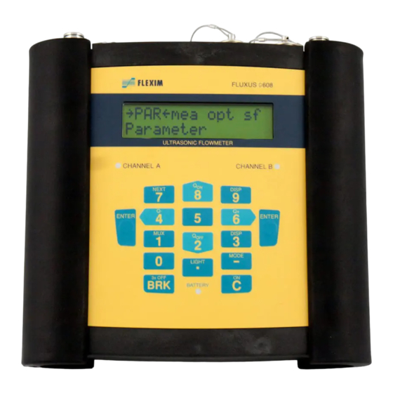
4 Transmitter Components
4.1 Transmitter Design
Overview of the transmitter's physical design, including display, keyboard, and indicator LEDs.
4.2 Status Indication
Explanation of the LED indicators for signal quality and battery status.
4.3 Serial Number Identification
Information on locating the transmitter's type and serial number for support.
4.4 Keyboard Functions
Detailed description of the transmitter's keyboard layout and functions for navigation and data input.
5 Selecting the Measuring Point
5.1 Acoustic Penetration Requirements
Criteria for pipe and medium acoustic penetrability for reliable sound signal propagation.
5.2 Ensuring an Undisturbed Flow Profile
Importance of selecting a measuring point away from flow disturbances for accurate measurement.
5.3 Minimizing the Influence of Noise
Explanation of how pipe wall signals can disturb measurements and points to avoid.
5.4 Optimizing Measuring Point Selection
Guidelines for selecting a measuring point considering both flow profile development and noise influence.
6 Installation of FLUXUS G601
6.1 Location Selection Criteria
Recommendations for selecting an appropriate location based on ambient temperature and measuring point requirements.
6.2 Transmitter Installation
Procedures for placing and hanging the transmitter unit, including support plate and handle usage.
6.3 Transducer Connection
Step-by-step guide for connecting the transducers to the transmitter, ensuring correct alignment.
6.4 Power Supply Options
Information on operating the transmitter using the battery or the external power supply unit.
6.5 Output Connections
Instructions for connecting various types of outputs, including analog and binary signals.
6.6 Input Connections
Details on connecting temperature probes and other inputs, including current and voltage sources.
6.7 Serial Interface Connection
Guidance on connecting the transmitter to a PC via the RS232 serial interface.
7 Installation of FLUXUS G608
7.1 Location Selection
Criteria for choosing the installation location considering ambient temperature and measuring point requirements.
7.2 Transmitter Installation
Steps for installing the transmitter, including placement, hanging, and pipe mounting.
7.3 Transducer Connection
Procedure for connecting the transducers to the transmitter, ensuring correct orientation and alignment.
7.4 Power Supply Options
Details on powering the transmitter via battery or external power adapter.
7.5 Output Connections (Optional)
Instructions for connecting optional output adapters for signal transmission.
7.6 Input Connections (Optional)
Guidelines for connecting optional temperature inputs and other input types.
7.7 Serial Interface Connection
Steps for connecting the transmitter's serial interface for data communication.
8 Mounting the Transducers
8.1 Pipe Surface Preparation
Steps for preparing the pipe surface, including cleaning and ensuring good thermal contact.
8.2 Damping Mat Installation
Procedure for mounting damping mats to reduce acoustic noise propagation in the pipe wall.
8.3 Transducer Positioning
Instructions for correctly positioning transducers on the pipe for optimal signal reception and flow direction determination.
9 Temperature Probe Installation (Optional)
9.1 Pipe Surface Cleaning for Temperature Probe
Procedure for cleaning the pipe surface to ensure good thermal contact for temperature measurement.
9.2 Temperature Probe Installation (50s Response)
Installation steps for temperature probes with a 50-second response time using various clasp types.
9.3 Temperature Probe Installation (8s Response)
Installation steps for temperature probes with an 8-second response time.
9.4 Temperature Probe Connection
Guide on connecting the temperature probe to the transmitter's temperature inputs.
10 Start-up Procedures
10.1 Switching the Transmitter On and Off
Instructions for powering the transmitter on and off using the BRK and C keys.
10.2 Understanding the Displays
Overview of the transmitter's display structure, including the main menu and program branches.
10.3 Using HotCodes for Settings
Explanation of HotCodes for activating specific settings like language selection and SuperUser mode.
10.4 Language Selection
Procedure for selecting the operating language of the transmitter using specific HotCodes.
11 Basic Measurement Configuration
11.1 Inputting Pipe Parameters
Guide for entering pipe dimensions, material, lining, and roughness for accurate measurements.
11.2 Inputting Medium Parameters
Procedure for entering medium properties like sound speed, viscosity, density, and compressibility factor.
11.3 Other Measurement Parameters
Configuration of additional parameters like transducer type and channel selection.
11.4 Channel Selection
Instructions on activating or deactivating measurement channels on the transmitter.
11.5 Defining Number of Sound Paths
Setting the number of sound paths based on transducer placement (reflection or diagonal mode).
11.6 Transducer Distance Adjustment
Guidance on setting and fine-tuning the transducer distance for optimal measurement accuracy.
11.7 Starting a Measurement
Procedure for initiating a measurement, including display of values and multiplexer operation.
11.8 Detecting Flow Direction
How to determine flow direction based on displayed volumetric flow rate and transducer arrows.
11.9 Stopping a Measurement
Instructions on how to interrupt or stop an ongoing measurement using the BRK key.
12 Displaying Measured Values
12.1 Selecting Physical Quantity and Unit
Guide to selecting the physical quantity (e.g., flow rate, velocity) and its unit of measurement.
12.2 Toggling Between Channels
Options for switching between measurement channels or displaying specific channels (AutoMux, HumanMux).
12.3 Adjusting the Display Layout
How to customize the display to show multiple measured values simultaneously.
12.4 Understanding the Status Line
Interpretation of the status line information for assessing measurement quality and precision.
12.5 Transducer Distance Display
Information on viewing the optimal and entered transducer distance during measurement.
13 Advanced Measuring Functions
13.1 Setting the Damping Factor
Adjusting the damping factor for averaging measured values and stabilizing readings.
13.2 Using Totalizers
Configuration and usage of totalizers for measuring total volume or mass over time.
13.3 Setting Upper Limit of Flow Velocity
Defining an upper limit for flow velocity to identify and ignore outliers.
13.4 Defining the Cut-off Flow
Setting a lower limit for flow velocity; values below this are set to zero.
13.5 Uncorrected Flow Velocity
Option to display flow velocity without profile correction for specific applications.
13.6 FastFood Mode for Dynamic Flows
Enabling and using FastFood mode for measuring flows with high dynamics.
13.7 Setting Up Calculation Channels
Configuring virtual channels for performing calculations based on measured channel data.
13.8 Adjusting Inner Pipe Diameter Limit
Changing the lower limit for the inner pipe diameter for specific transducer types.
14 Data Logger and Data Transmission
14.1 Data Logger Configuration
Details on activating, setting storage rates, and configuring the data logger.
14.2 Data Transmission to PC
Procedures for transmitting data online or offline via RS232 interface.
14.2.8 Data Structure Overview
Explanation of the data header and column format transmitted during measurement.
15 Working with Parameter Records
15.1 Introduction to Parameter Records
Explanation of parameter records for storing measurement configurations and simplifying repetitive tasks.
15.2 Storing a Parameter Record
Steps for saving current measurement parameters as a named record for later use.
15.3 Loading a Parameter Record
Procedure for retrieving and applying previously stored parameter records for new measurements.
15.4 Deleting Parameter Records
Instructions on how to remove stored parameter records from the transmitter's memory.
16 Libraries for Materials and Media
16.1 Coefficient Memory Partitioning
How to partition the coefficient memory for storing user-defined material and medium properties.
16.2 Inputting Material/Medium Properties (Basic)
Entering material/medium properties as constants without using the extended library.
16.3 Extended Library for Material/Medium Properties
Activating and using the extended library for temperature/pressure-dependent properties.
16.4 Deleting User Defined Material/Medium
Procedure for removing user-defined materials or media from the transmitter's database.
16.5 Arranging Material/Medium Scroll Lists
Customizing the displayed lists of materials and media in the Parameter branch.
17 Device Settings
17.1 Setting Time and Date
Instructions for setting the transmitter's internal clock for accurate time-stamping of measurements.
17.2 Dialogs and Menus Configuration
Adjusting menu settings, including pipe circumference input and medium pressure handling.
17.3 Measurement Settings
Configuring measurement parameters, including gas measurement activation and sound speed comparison.
17.4 Standard Conditions for Gas Measurement
Setting standard pressure and temperature for gas measurements.
17.5 Adjusting Display Contrast
How to adjust the display contrast for optimal readability.
17.6 Instrument Information
Accessing information about the transmitter, including serial number and firmware version.
18 SuperUser Mode Operations
18.1 Activating and Deactivating SuperUser Mode
Procedure for enabling and disabling the SuperUser mode for advanced analysis.
18.2 Setting Transducer Parameters
Configuring transducer parameters within the SuperUser mode, including special versions.
18.3 Defining Flow Parameters
Setting flow parameters like profile bounds and velocity correction in SuperUser mode.
18.4 Limiting Signal Amplification
Setting a maximum gain threshold to prevent interference from pipe wall signals.
18.5 Setting Upper Limit of Sound Speed
Defining an upper limit for sound speed evaluation to assess signal plausibility.
18.6 Decimal Places for Totalizers
Configuring the number of decimal places for displaying totalizer values.
18.7 Manual Reset of Totalizers
Activating manual reset functionality for totalizers.
18.8 Displaying Sum of Totalizers
Enabling the display of the sum of totalizers in the upper line.
18.9 Display During Measurement (SuperUser)
Viewing additional information during measurements in SuperUser mode.
19 Wall Thickness Measurement (Optional)
19.1 Activating Wall Thickness Measurement
Procedure for connecting the wall thickness probe and activating the measurement mode.
19.2 Parameter Input for Wall Thickness
Entering pipe material and sound speed for accurate wall thickness measurement.
19.3 Performing the Measurement
Steps for conducting wall thickness and sound speed measurements, including error handling.
20 Configuring Inputs
20.1 Assigning Temperature Inputs to Channels
Linking temperature inputs to specific measuring channels.
20.2 Selecting Temperature Probes
Choosing the type of temperature probe (e.g., PT100) to be used with the transmitter.
20.3 Assigning Other Inputs to Channels
Linking other types of inputs (e.g., current) to measuring channels.
20.4 Activating Inputs
Enabling temperature and other inputs for measurement and data storage.
20.5 Temperature Correction Settings
Applying temperature correction offsets to measured temperature values.
21 Configuring Outputs
21.1 Installing and Configuring Outputs
Steps for installing, enabling, and assigning channels/quantities to transmitter outputs.
21.2 Setting Error Value Delay
Configuring the delay time before transmitting an error value when no valid data is available.
21.3 Activating Analog Outputs
Enabling analog outputs and defining their measuring range.
21.4 Frequency Output as Pulse Output
Configuring frequency outputs to act as pulse outputs for totalizing.
21.5 Binary Output as Pulse Output
Activating binary outputs to function as pulse outputs based on given pulse values.
21.6 Binary Output as Alarm Output
Configuring binary outputs to function as alarm outputs with defined switching conditions.
21.7 Alarm Output Behavior
Understanding how alarm outputs behave, including switching delays and reset conditions.
21.8 Deactivating Outputs
Procedure for disabling programmed outputs when they are no longer needed.
22 Troubleshooting Common Issues
Troubleshooting: Calibration Issues
Information on when recalibration is recommended and the process for sending the transmitter for service.
Troubleshooting: Display Problems
Guidance for resolving issues with the display, including SYSTEM ERROR messages and backlight failures.
Troubleshooting: Date and Time Errors
Steps to resolve incorrect date/time settings and data loss upon power off.
Troubleshooting: Output Malfunctions
Steps to diagnose and resolve issues where outputs are not functioning correctly.
Troubleshooting: Measurement Failures
Addressing situations where measurements are impossible or yield significantly incorrect values.
Troubleshooting: Totalizer Value Errors
Diagnosing and resolving problems related to incorrect totalizer values.
22.1 Measurement Signal Issues
Troubleshooting steps for when no signal is received or measured values are not obtained.
22.2 Measuring Point Selection Issues
Guidance on selecting an appropriate measuring point to ensure reliable results.
22.3 Ensuring Maximum Acoustic Contact
Recommendations for achieving optimal acoustic contact between transducers and the pipe.
22.4 Application Specific Problems
Addressing issues related to incorrect medium sound speed, pipe roughness, or porous pipe materials.
22.5 Handling Large Deviations in Measured Values
Identifying causes for significant deviations in measured values, such as wrong parameters or limits.
22.6 Totalizer Problems Resolution
Troubleshooting steps for totalizer values being too high, too low, or sums being incorrect.
22.7 Data Transmission Errors
Resolving issues with meaningless strings in transmitted data due to parameter mismatches.
Annex A: Menu Structure
Menu Navigation: Parameter Branch
Overview of the Parameter branch menu structure for configuring measurement settings.
Menu Navigation: Measuring Branch
Structure of the Measuring branch menu for initiating and managing measurements.
Menu Navigation: Output Options Branch
Layout of the Output Options branch for configuring transmitter outputs.
Menu Navigation: Special Funct. Branch
Structure of the Special Function branch for accessing advanced settings and utilities.
B Technical Data
FLUXUS G601 Transmitter Specifications
Technical details for the FLUXUS G601 transmitter, covering design, measurement, power, and display.
FLUXUS G601 Data Logger and Communication
Specifications for the data logger, communication interface, and software.
FLUXUS G601 Outputs and Inputs
Technical specifications for transmitter outputs (current, frequency, binary) and inputs.
FLUXUS G608 Transmitter Specifications
Technical details for the FLUXUS G608 transmitter, including explosion protection ratings.
FLUXUS G608 Explosion Protection & Outputs
Explosion protection details for G608, and specifications for its outputs.
Optional Adapters Specifications
Technical data for optional output and power adapters.
Shear Wave Transducers Specifications
Technical data for various Shear Wave Transducers, including dimensions and operating temperatures.
Lamb Wave Transducers Specifications
Technical data for Lamb Wave Transducers, covering pressure, pipe diameter, and temperature ranges.
Damping Mats (Optional) Selection
Guidelines for selecting and using damping mats for noise reduction in gas measurements.
Units of Measurement Reference
A reference table for units of measurement across different physical quantities.
Flow Nomogram (Metrical)
A metrical nomogram for determining flow rates based on flow velocity and pipe diameter.
Flow Nomogram (Imperial)
An imperial nomogram for determining flow rates based on flow velocity and pipe diameter.
C Reference Data
C.1 Sound Speed of Pipe and Lining Materials
Table of sound speeds for various pipe and lining materials at 20 °C.
C.2 Typical Pipe Roughnesses
Reference values for typical pipe surface roughness based on material and condition.
C.3 Typical Properties of Selected Media
Reference data for properties of selected media (e.g., methane, glycol) at 20 °C and 1 bar.
Need help?
Do you have a question about the FLUXUS G608 and is the answer not in the manual?
Questions and answers