Table of Contents
Advertisement
Advertisement
Table of Contents

Related Manuals for Flexim FLUXUS F60 Series


Summary of Contents for Flexim FLUXUS F60 Series
- Page 1 Operating instruction FLUXUS F60* UMFLUXUS_F60xV5-0EN...
- Page 2 FLUXUS is a registered trademark of FLEXIM GmbH. FLEXIM GmbH Boxberger Straße 4 12681 Berlin Germany Tel.: +49 (30) 936 67 660 Fax: +49 (30) 936 67 680 E-mail: info@flexim.com www.flexim.com Operating instruction for FLUXUS F60* UMFLUXUS_F60xV5-0EN, 2017-10-16 Firmware version: V6.28 Copyright (©) FLEXIM GmbH 2017...
-
Page 3: Table Of Contents
FLUXUS F60* Table of contents Table of contents Introduction ........... 7 Safety instructions . - Page 4 Table of contents FLUXUS F60* Program branches ..........76 HotCodes .
- Page 5 FLUXUS F60* Table of contents 14.2 Assignment of other inputs to the measuring channels ....131 14.3 Activation of the inputs ......... 132 14.4 Temperature correction .
- Page 6 Table of contents FLUXUS F60* 18.5 Upper limit of the sound speed ........179 18.6 Detection of long measurement failures .
-
Page 7: Introduction
1 Introduction FLUXUS F60* Introduction This operating instruction has been written for users operating the ultrasonic flowmeter FLUXUS. It contains important information about the measuring equipment, how to han- dle it correctly, and how to avoid damages. Read the safety instructions carefully. Make sure you have read and understood this operating instruction before using the measuring equipment. - Page 8 Copyright The contents of this operating instruction are subject to changes without prior notice. All rights reserved. No part of this operating instruction may be reproduced in any form with- out FLEXIM's written permission. 2017-10-16, UMFLUXUSF60xV5-0EN...
-
Page 9: Safety Instructions
Failure to comply with the instructions, in particular with the safety instructions, poses a risk to health and can lead to material damages. For further information, contact FLEXIM. During installation and operation of the measuring equipment, observe the ambient and installation conditions specified in the documentation. -
Page 10: Not Intended Use
• With the exceptions stated in chapter 10, the measuring equipment is maintenance- free. Any components and spare parts may only be replaced by FLEXIM. The operator shall carry out periodic checks for changes or damages that can present a danger. For further information, contact FLEXIM. -
Page 11: Safety Instructions For Electrical Work
• The transmitter, transducers and accessories have to be properly packed for transport: – Use, if possible, the original packaging by FLEXIM or an equivalent cardboard box. – Position the transmitter, transducers and accessories in the middle of the cardboard box. -
Page 12: Recommended Procedure In Hazardous Situations
2 Safety instructions 2.8 Recommended procedure in hazardous situations FLUXUS F60* Recommended procedure in hazardous situations Fire fighting measures • If possible, disconnect the transmitter from the power supply. • Prior to extinguishing, protect any electrical parts that are not affected by the fire (e.g., using a cover). -
Page 13: General Principles
3 General principles FLUXUS F60* 3.1 Measurement principle General principles For the ultrasonic measurement of the flow rate, the flow velocity of the fluid in a pipe is determined. Further physical quantities are derived from the flow velocity and from addi- tional physical quantities, if necessary. - Page 14 3 General principles 3.1 Measurement principle FLUXUS F60* Acoustic calibration factor k ----------- - The acoustic calibration factor k is a transducer parameter which results from the sound speed c within the transducer and the angle of incidence. According to Snell's law of re- fraction, the angle of propagation in the adjoining fluid or pipe material is: ...
- Page 15 3 General principles FLUXUS F60* 3.1 Measurement principle 3.1.2 Measurement of the flow velocity in the TransitTime mode The signals are emitted and received by two transducers alternatively in and against the flow direction. If the fluid is flowing, the signals propagating in the fluid are displaced with the flow.
- Page 16 3 General principles 3.1 Measurement principle FLUXUS F60* Fig. 3.2: Sound path of the signal against the flow direction distance increase within the transducer α α α β β sound path without γ flow γ sound path with flow flow direction of the fluid c –...
- Page 17 3 General principles FLUXUS F60* 3.1 Measurement principle 3.1.3 Measurement of the flow velocity in the NoiseTrek mode If the proportion of gas or solids in the fluid is high, the damping of the ultrasonic signal can be so high that the complete propagation of the fluid and therefore a measurement in TransitTime mode is not possible anymore.
- Page 18 3 General principles 3.1 Measurement principle FLUXUS F60* 3.1.4 Measurement of the flow velocity in the HybridTrek mode The HybridTrek mode combines the TransitTime and the NoiseTrek mode. During a measurement in the HybridTrek mode, the transmitter automatically toggles between the TransitTime and the NoiseTrek mode depending on the gaseous or solid content.
-
Page 19: Measurement Arrangements
3 General principles FLUXUS F60* 3.2 Measurement arrangements Measurement arrangements 3.2.1 Terms Diagonal arrangement Reflection arrangement The transducers are mounted on opposite The transducers are mounted on the same sides of the pipe. side of the pipe. Sound path The distance covered by the ultrasonic signal after crossing the pipe once. The number of the sound paths is: •... - Page 20 3 General principles 3.2 Measurement arrangements FLUXUS F60* Transducer distance The transducer distance is measured between the inner edges of the transducers. reflection arrangement diagonal arrangement (positive transducer distance) diagonal arrangement (negative transducer distance) a – transducer distance Sound beam plane Plane containing 1 or several sound paths or beams.
- Page 21 3 General principles FLUXUS F60* 3.2 Measurement arrangements 3.2.2 Examples Diagonal arrangement with 1 beam Reflection arrangement with 1 beam 1 transducer pair 1 transducer pair 1 sound path 2 sound paths 1 beam 1 beam 1 plane 1 plane Diagonal arrangement with 2 beams Reflection arrangement with 2 beams and 2 planes...
-
Page 22: Acoustic Penetration
3 General principles 3.3 Acoustic penetration FLUXUS F60* Acoustic penetration The pipe has to be acoustically penetrable at the measuring point. The acoustic penetra- tion is reached when pipe and fluid do not attenuate the sound signal so strongly that it is completely absorbed before reaching the second transducer. - Page 23 3 General principles FLUXUS F60* 3.3 Acoustic penetration Vertical pipe Select the measuring point at a pipe location where the fluid flows upward. The pipe has to be completely filled, see Fig. 3.12 and Fig. 3.13. Fig. 3.12: Recommended transducer Fig.
-
Page 24: Undisturbed Flow Profile
3 General principles 3.4 Undisturbed flow profile FLUXUS F60* Undisturbed flow profile Some flow elements (e.g., elbows, valves, pumps, reducers) distort the flow profile in their vicinity. The axisymmetrical flow profile in the pipe needed for correct measurement is no longer given. A careful selection of the measuring point helps to reduce the impact of disturbance sources. - Page 25 3 General principles FLUXUS F60* 3.4 Undisturbed flow profile Tab. 3.1: Recommended distance from disturbance sources D – nominal pipe diameter at the measuring point l – recommended distance between disturbance source and transducer position disturbance source: valve inlet: l ≥ 40 D outlet: l ≥...
-
Page 26: Product Description
4 Product description 4.1 Measuring system FLUXUS F60* Product description Measuring system The measurement system consists of a transmitter, the ultrasonic transducers and the pipe on which the measurement is carried out, see Fig. 4.1. Fig. 4.1: Example of a measurement setup 1 –... - Page 27 4 Product description FLUXUS F60* 4.2 Handling concept Fig. 4.2: Command panel of the transmitter >PAR< mea opt sf Parameter 1 – display 2 – keyboard For a description of the individual program branches, see Tab. 4.1. Tab. 4.1: Description of the program branches program branch description Before starting a measurement, the transducer, pipe and fluid param-...
-
Page 28: Navigation
4 Product description 4.3 Navigation FLUXUS F60* Navigation 4.3.1 Scroll lists If a vertical arrow ↕ is displayed, the menu item contains a scroll list. The current list item is displayed in the lower line. Parameter ↕ for Channel • Press key to scroll and select a list item in the lower line. -
Page 29: Keyboard
4 Product description FLUXUS F60* 4.4 Keyboard Keyboard The keyboard has 15 keys, including 3 function keys: ENTER, BRK and C. Some key have multiple functions. They can be used to enter data, to navigate through scroll lists as well as to execute special functions (e.g., reset of totalizers). Tab. - Page 30 4 Product description 4.4 Keyboard FLUXUS F60* Tab. 4.5: Input of text positioning of the cursor "A" is displayed and capitalization is activated "Z" is displayed and capitalization is activated toggling between upper and lower case selection of the previous/next character deletion of a character and insertion of a blank Automatic scrolling up or down through the limited ASCII character set.
-
Page 31: Transport And Storage
5 Transport and storage FLUXUS F60* 5.1 Transport Transport and storage Caution! When packaging, the transmitter can fall down. There is a danger of crushing body parts or damaging the measuring equipment. → Secure the transmitter against falling during packaging. Wear the required personal protective equipment. -
Page 32: Installation
6 Installation FLUXUS F60* Installation Danger! Risk of explosion when using the transmitter FLUXUS *608**-A2 in explosive atmospheres This may result in personal or material damage or other dangerous situa- tions. → Observe the "Safety instructions for the use in explosive atmospheres", see document SIFLUXUS_608. -
Page 33: Transmitter
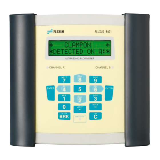
6 Installation FLUXUS F60* 6.1 Transmitter Transmitter 6.1.1 Transmitter design Fig. 6.1: Command panel of the transmitter 1 – display, 2 × 16-digit (backlight) 2 – status indication "SIGNAL" 3 – keyboard 4 – state indicator "BATTERY" A handle is mounted on the rear side of the transmitter, see Fig. 6.2. The handle can also be used as support. - Page 34 6 Installation 6.1 Transmitter FLUXUS F60* 6.1.2 Installation of the transmitter 6.1.2.1 Placement Pull the support back to the stop of the support plate, see Fig. 6.3. Fig. 6.3: Placement of the transmitter 1 – handle 2 – support plate 6.1.2.2 Suspension Press both ends of the handle outwards and pass them past the support plate.
- Page 35 6 Installation FLUXUS F60* 6.1 Transmitter 6.1.2.3 Pipe installation Notice! The pipe temperature must not exceed the operating temperature of the transmitter. Fix the tension belt with the button to the pipe. Tighten the belt using the ratchet. Insert the button into the opening in the support plate on the rear side of the transmitter, see Fig.
-
Page 36: Transducers
6 Installation 6.2 Transducers FLUXUS F60* Transducers 6.2.1 Preparation 6.2.1.1 Measuring point selection The correct selection of the measuring point is crucial for achieving reliable measure- ment results and a high measurement accuracy. A measurement on a pipe is possible if: •... - Page 37 6 Installation FLUXUS F60* 6.2 Transducers Notice! Observe the selection criteria for the pipe and the measuring point. Rust, paint or deposits on the pipe absorb the sound signal. A good acoustic contact be- tween the pipe and the transducers is obtained as follows: •...
- Page 38 6 Installation 6.2 Transducers FLUXUS F60* Diagonal arrangement with 2 beams Reflection arrangement with 2 beams and 2 planes X arrangement • same characteristics as reflection ar- rangement with 2 beams • additional characteristic: influences of the flow profile are compen- sated because the measurement takes place in 2 planes displaced X arrangement...
- Page 39 6 Installation FLUXUS F60* 6.2 Transducers If the measuring point is situated near an elbow, the following measurement arrange- ments are recommended for the selection of the sound beam plane. Vertical pipes Horizontal pipes flow direction elbow plane elbow plane flow direction •...
- Page 40 6 Installation 6.2 Transducers FLUXUS F60* 6.2.2 Installation of the transducers Notice! Handle the transducer cable with care. Avoid sharp bends or kinks, especially at simultaneous strain. 6.2.2.1 Orientation of the transducers and determination of the transducer distance Observe the orientation of the transducers. If the transducers have been mounted prop- erly, the engravings on the transducers form an arrow, see Fig.
- Page 41 6 Installation FLUXUS F60* 6.2 Transducers Fig. 6.8: Installation of the transducers with fastening shoes and chains Extension of the ball chain In order to extend the chain, insert the last ball of the extension into the fastening clip of the ball chain.
- Page 42 6 Installation 6.2 Transducers FLUXUS F60* 6.2.2.4 Installation of the transducers with portable Variofix rail and chains Normally, each transducer is mounted in its own Variofix rail. If the transducer distance is small and both transducers are on the same side of the pipe (reflection arrangement), both transducers can be fixed in one Variofix rail.
-
Page 43: Temperature Probe
6 Installation FLUXUS F60* 6.3 Temperature probe Fig. 6.10: Variofix rail with chains 1 – screw 2 – rail 3 – transducer 4 – chain tensioner 5 – horizontal groove 6 – rail support 7 – cylinder 8 – ball chain 9 –... - Page 44 Select the installation instructions according to the supplied clasp: • for the installation with clasp, see section 6.3.2.1 • for the installation with FLEXIM clasp, see section 6.3.2.2 • for the installation with quick release clasp, see section 6.3.2.3 6.3.2.1...
- Page 45 Fig. 6.11: Clasp Fig. 6.12: Temperature probe on the pipe 6.3.2.2 Installation with FLEXIM clasp Caution! The edge of the tension strap is very sharp. Risk of injury! → Debur sharp edges. → Wear the required personal protective equipment. Observe the appli- cable rules.
- Page 46 6 Installation 6.3 Temperature probe FLUXUS F60* Fig. 6.13: FLEXIM clasp 6.3.2.3 Installation with quick release clasp Caution! The edge of the tension strap is very sharp. Risk of injury! → Debur sharp edges. → Wear the required personal protective equipment. Observe the appli- cable rules.
- Page 47 6 Installation FLUXUS F60* 6.3 Temperature probe 6.3.3 Installation of the temperature probe (response time 8 s) • Fix the protection plate and the insulation foam to the temperature probe, see Fig. 6.15. • Take the spring end of the chain and insert the first ball into one of the slots on the up- per side of the temperature probe, see Fig.
-
Page 48: Connection
7 Connection 7.1 FLUXUS *601 FLUXUS F60* Connection FLUXUS *601 7.1.1 Transducers The connections are on the upper side of the transmitter, see Fig. 7.1. • Pull up the socket cover, see Fig. 7.2. • Insert the connector of the transducer cable into the socket of the transmitter. The red point (a) on the connector has to be aligned with the red marking (b) on the socket. - Page 49 7 Connection FLUXUS F60* 7.1 FLUXUS *601 7.1.2 Power supply The transmitter can be operated with the integrated battery, the power supply unit or the power pack PP026NN, see document QSPowerPack_PP026. 7.1.2.1 Operation with battery The transmitter has a Li-ion battery and can therefore be operated independently. When delivered, the battery is charged with approx.
- Page 50 7 Connection 7.1 FLUXUS *601 FLUXUS F60* Charging the battery Connect the power supply to the transmitter, see section 7.1.2.2. Switch on the transmit- ter. The charging starts automatically. The LED "BATTERY" flashes green while charging. The max. charging time is approx. 8 h. During the charging process, the ambient temperature should be in the range of 0...45 °C.
- Page 51 7 Connection FLUXUS F60* 7.1 FLUXUS *601 Automatic power-off In battery mode, the transmitter has an automatic power-off. The transmitter will be switched off if • no measurement is being made and no key is pressed within 10 min or •...
- Page 52 7 Connection 7.1 FLUXUS *601 FLUXUS F60* 7.1.3 Outputs Notice! For the connection, observe the specifications regarding the assignment of the out- puts given on the nameplate on the backside of the transmitter. Notice! The max. voltage between the outputs and the internal power supply of the transmit- ter is 42 V DC (permanent).
- Page 53 7 Connection FLUXUS F60* 7.1 FLUXUS *601 Tab. 7.1: Circuit of the outputs output transmitter external circuit remark internal connection circuit passive = 4…26 V current > 0.021 A · R [Ω] + 4 V output example: = 12 V ≤...
- Page 54 7 Connection 7.1 FLUXUS *601 FLUXUS F60* 7.1.4 Inputs Notice! For the connection, observe the specifications regarding the assignment of the inputs given on the nameplate on the backside of the transmitter. Notice! The max. voltage between the inputs and the internal power supply of the transmit- ter is 42 V DC (permanent).
- Page 55 7 Connection FLUXUS F60* 7.1 FLUXUS *601 If the polarity of the current source is inversed, only the sign of the measured current will change. Tab. 7.3: Connection of a passive current source input transmitter external circuit remark internal circuit connection passive short circuit current:...
- Page 56 7 Connection 7.1 FLUXUS *601 FLUXUS F60* 7.1.4.3 Input adapter The number of temperature inputs can be increased to max. 4 by means of 2 input adapt- ers (optional), see Fig. 7.7. If the transmitter has voltage or current inputs, the adapter for voltage and current inputs will be used, see Fig.
- Page 57 7 Connection FLUXUS F60* 7.1 FLUXUS *601 Fig. 7.8: Connection of the adapter for the voltage and current inputs P3...P8 T1/T3 T2/T4 CH A CH B COMM DC-IN Output Input 1 – input adapter 2 – adapter for voltage and current inputs 7.1.4.4 Connection of an active input For the connection of a passive current source to a passive current input, an external...
- Page 58 7 Connection 7.1 FLUXUS *601 FLUXUS F60* Fig. 7.9: Connection of the adapter for the active current input P3...P8 T1/T3 T2/T4 CH A CH B COMM DC-IN Output Input passive current source 1 – input adapter 2 – adapter for the active current input 3 –...
- Page 59 7 Connection FLUXUS F60* 7.1 FLUXUS *601 7.1.5 Serial interface • Connect the RS232 cable to the transmitter, see Fig. 7.10, and to the serial interface of the PC. • Use the RS232 adapter for the connection of the RS232 cable to the transmitter. If the RS232 cable cannot be connected to the PC, use the RS232/USB adapter.
-
Page 60: Fluxus *608
7 Connection 7.2 FLUXUS *608 FLUXUS F60* FLUXUS *608 Danger! Risk of explosion when using the transmitter FLUXUS *608**-A2 in explosive atmospheres This may result in personal or material damage or other dangerous situa- tions. → Observe the "Safety instructions for the use in explosive atmospheres", (see document SIFLUXUS_608). - Page 61 7 Connection FLUXUS F60* 7.2 FLUXUS *608 Fig. 7.12: Removal of the blind plug Fig. 7.13: Transducer connection FLUXUS *608**-F2 The connections are on the upper side of the transmitter, see Fig. 7.14. • Remove the substitute plug, if present. •...
- Page 62 7 Connection 7.2 FLUXUS *608 FLUXUS F60* Fig. 7.14: Connection of the transducers to the transmitter CH A CH B COMM DC-IN 1 – transducers (measuring channel A) 2 – transducers (measuring channel B) Fig. 7.15: Transducer connection Fig. 7.16: Transducer connection 1 –...
- Page 63 7 Connection FLUXUS F60* 7.2 FLUXUS *608 7.2.2 Power supply The transmitter can be operated with the integrated battery, the power cable with power adapter (FLUXUS *608**-A2 only) or the power supply unit (FLUXUS *608**-F2 only). 7.2.2.1 Operation with battery The transmitter has a Li-ion battery and can therefore be operated independently.
- Page 64 7 Connection 7.2 FLUXUS *608 FLUXUS F60* Charging the battery Connect the power supply to the transmitter, see Fig. 7.17 or Fig. 7.18. Switch on the transmitter. The charging starts automatically. The LED "BATTERY" flashes green while charging. The max. charging time is approx. 8 h. During the charging process, the ambient temperature should be in the range of 0...45 °C.
- Page 65 7 Connection FLUXUS F60* 7.2 FLUXUS *608 Maintenance (relearn cycle) The accuracy of the displayed value for the charge state of the battery is improved by ex- ecuting a relearn cycle. The ambient temperature during a relearn cycle should be in the range of 12...30 °C.
- Page 66 7 Connection 7.2 FLUXUS *608 FLUXUS F60* 7.2.2.2 Power supply with cable and adapter (optional) FLUXUS *608**-A2 The power adapter has to be used for the connection of the power cable. Fig. 7.19: Connection of the power adapter to the transmitter CH A CH B DC-IN...
- Page 67 7 Connection FLUXUS F60* 7.2 FLUXUS *608 Fig. 7.20: Cable gland 1 – cap nut 2 – compression part 3 – basic part 4 – gasket ring side of the basic part • Remove the blind plug, see Fig. 7.19. •...
- Page 68 7 Connection 7.2 FLUXUS *608 FLUXUS F60* Fig. 7.21: Connections on the transmitter CH A CH B COMM DC-IN 1 – power supply unit/battery charging unit 7.2.3 Outputs The output adapter has to be used for the connection of the output adapters, see Fig. 7.22.
- Page 69 7 Connection FLUXUS F60* 7.2 FLUXUS *608 Fig. 7.22: Connection of the output adapter to the transmitter CH A CH B DC-IN COMM Input Output 1 – power adapter 2 – blind plug 3 – connection of the outputs UMFLUXUS_F60xV5-0EN, 2017-10-16...
- Page 70 7 Connection 7.2 FLUXUS *608 FLUXUS F60* Fig. 7.23: Cable gland 1 – cap nut 2 – compression part 3 – basic part 4 – gasket ring side of the basic part Tab. 7.6: Circuit of the outputs output transmitter external circuit remark internal...
- Page 71 7 Connection FLUXUS F60* 7.2 FLUXUS *608 7.2.4 Inputs (optional) Notice! For the connection, observe the specifications regarding the assignment of the inputs given on the nameplate on the backside of the transmitter. Notice! The max. voltage between the inputs and the internal power supply of the transmit- ter is 42 V DC (permanent).
- Page 72 7 Connection 7.2 FLUXUS *608 FLUXUS F60* 7.2.4.2 Input adapter (optional) The number of temperature inputs can be increased to max. 4 by means of 2 input adapters. Fig. 7.26: Connection of the input adapter to the transmitter FLUXUS *608**-A2 CH A CH B DC-IN...
- Page 73 7 Connection FLUXUS F60* 7.2 FLUXUS *608 7.2.5 Serial interface • Connect the RS232 cable to the transmitter and the serial interface of the PC. • Use the RS232 adapter for the connection of the RS232 cable to the transmitter. If the RS232 cable cannot be connected to the PC, use the RS232/USB adapter.
-
Page 74: Start-Up
8 Start-up 8.1 Start-up settings FLUXUS F60* Start-up Danger! Risk of explosion when using the transmitter FLUXUS *608**-A2 in explosive atmospheres This may result in personal or material damage or other dangerous situa- tions. → Observe the "Safety instructions for the use in explosive atmospheres", see document SIFLUXUS_608. -
Page 75: Switching On/Off
8 Start-up FLUXUS F60* 8.2 Switching on/off CANADA-REGION • Select yes if the transmitter is to be used in the region of Canada. • Press ENTER. This display will only be indicated if imperial is selected. TIME The current time is displayed. •... -
Page 76: Fluxus F60
8 Start-up 8.3 Program branches FLUXUS F60* Program branches The following illustration provides an overview of the program branches. For a detailed overview of the menu structure, see annex A. Parameter Measuring Output Options Special Funct. Selection of measuring Selection of measuring Selection of measuring System settings channel... -
Page 77: Hotcodes
8 Start-up FLUXUS F60* 8.4 HotCodes HotCodes A HotCode is a digit sequence that activates certain functions and settings. A HotCode can only be entered in the main menu immediately after the transmitter has been switched on. The HotCode is not displayed during the input. function HotCode deactivation... -
Page 78: Initialization
8 Start-up 8.6 Initialization FLUXUS F60* Initialization During an initialization (INIT) of the transmitter, the settings in the program branches Parameter and Output Options and some of the settings in the program branch Special Funct. are reset to the default settings of the manufacturer. Proceed as follows to execute an initialization: •... -
Page 79: Time And Date
8 Start-up FLUXUS F60* 8.7 Time and date Time and date The transmitter has a battery-powered clock. Measured values are automatically stored with date and time. Special Funct.\SYSTEM settings\Set Clock\TIME • Select the menu item Set Clock. • Press ENTER. The current time is displayed. -
Page 80: Instrument Information
8 Start-up 8.8 Instrument information FLUXUS F60* Instrument information Special Funct.\Instrum. Inform. • Select the menu item Instrum. Inform. to get information about the transmitter. • Press ENTER. F60x -XXXXXXXX The type and the serial number of the transmitter are displayed in the upper line. Free: 18327 The max. -
Page 81: Measurement
9 Measurement FLUXUS F60* Measurement Danger! Risk of explosion when using the transmitter FLUXUS *608**-A2 in explosive atmospheres This may result in personal or material damage or other dangerous situa- tions. → Observe the "Safety instructions for the use in explosive atmospheres", see document SIFLUXUS_608. -
Page 82: Parameter Input
9 Measurement 9.1 Parameter input FLUXUS F60* Parameter input Parameter for Channel … Outer Diameter Wall Thickness Pipe Material Lining Roughness Medium Medium Temperat. Transducer Type see annex A, p. 220 The pipe and fluid parameters are entered for the selected measuring point. The param- eter ranges are limited by the technical characteristics of the transducers and the trans- mitter. - Page 83 9 Measurement FLUXUS F60* 9.1 Parameter input 9.1.1 Input of pipe parameters Outer pipe diameter/pipe circumference Parameter\Outer Diameter • Enter the outer pipe diameter. • Press ENTER. An error message will be displayed if the entered parameter is outside the range. The limit is displayed.
- Page 84 9 Measurement 9.1 Parameter input FLUXUS F60* Pipe material Parameter\Pipe Material The pipe material has to be selected to be able to determine the corresponding sound speed. The sound speeds for the materials in the scroll list are stored in the transmitter. •...
- Page 85 9 Measurement FLUXUS F60* 9.1 Parameter input Sound speed of the lining material Parameter\Lining\Other Material\c-Material • Enter the sound speed of the lining material. • Press ENTER. Notice! For pipe materials there are 2 sound speeds, the longitudinal and the transversal one.
- Page 86 9 Measurement 9.1 Parameter input FLUXUS F60* 9.1.2 Input of fluid parameters Fluid Parameter\Medium • Select the fluid from the scroll list. • Press ENTER. If the fluid is not in the scroll list, select Other Medium. It is possible to specify which fluids will be displayed in the scroll list, see section 19.4. If a fluid is selected from the scroll list, the menu item for the input of the fluid temperature is displayed directly.
- Page 87 9 Measurement FLUXUS F60* 9.1 Parameter input Parameter\Medium\Other Medium\c-Medium range\c-Medium • Enter the range around the average sound speed of the fluid. • Press ENTER. This display will only be indicated if user is selected. Kinematic viscosity of the fluid Parameter\Medium\Other Medium\Kinem.Viscosity The kinematic viscosity influences the flow profile of the fluid.
- Page 88 Parameter\Transducer Type • Select Standard to use the standard transducer parameters stored in the transmitter. • Select Special Version to enter the transducer parameters. The transducer param- eters have to be provided by FLEXIM. • Press ENTER. Notice! If a standard transducer is selected, no transducer-specific calibration values are considered.
-
Page 89: Measurement Settings
9 Measurement FLUXUS F60* 9.2 Measurement settings Measurement settings 9.2.1 Selection of the physical quantity and the unit of measurement Output Options for Channel A: Physic. Quant. Unit Of Measure Damping see annex A, p. 221 The following physical quantities can be measured: •... - Page 90 9 Measurement 9.2 Measurement settings FLUXUS F60* Output Options\for Channel A:\Physic. Quant.\Volume flow For the selected physical quantity (except for the sound speed), a scroll list with the avail- able units of measurement is displayed. The unit of measurement which was selected previously is displayed first.
- Page 91 9 Measurement FLUXUS F60* 9.2 Measurement settings 9.2.3 Installation of an output SYSTEM settings Proc. outputs Install Output enable Source chan. Source item see annex A, p. 224 If the transmitter is equipped with outputs, they have to be installed and activated before they can be used: •...
- Page 92 9 Measurement 9.2 Measurement settings FLUXUS F60* Selection of an output Special Funct.\SYSTEM settings\Proc. outputs\Install Output • Select the output to be installed. • Press ENTER. The scroll list contains all available outputs of the transmitter: – Current IX (--) –...
- Page 93 9 Measurement FLUXUS F60* 9.2 Measurement settings Tab. 9.1: Configuration of outputs source item list item output physical quantity selected in the program Measuring value actual measure branch Output Options flow, independently of the physical quantity se- Flow lected in the program branch Output Op- tions heat flow, independent of the physical quantity Heatflow...
- Page 94 9 Measurement 9.2 Measurement settings FLUXUS F60* Tab. 9.1: Configuration of outputs source item list item output is only available if a temperature input has been assigned to the channel Temperature fluid temperature measured by the temperature Tfluid ← (Ti)* probe at the point where the flow is measured fluid temperature measured by the other tem- Taux S/R ←...
- Page 95 9 Measurement FLUXUS F60* 9.2 Measurement settings 9.2.3.1 Output of the measured value Source item Output range Error-value active loop Output Test see annex A, p. 224 When configuring an analog output, the output range is defined. • Select Special Funct.\SYSTEM settings\Proc. outputs\...\I1 Output range.
- Page 96 9 Measurement 9.2 Measurement settings FLUXUS F60* Notice! The settings will be stored at the end of the dialog. Tab. 9.2: Error output error value result the lower limit of the output range is output Minimum the last measured value is output Hold last value the upper limit of the output range is output Maximum...
- Page 97 9 Measurement FLUXUS F60* 9.2 Measurement settings Tab. 9.3: Examples for the error output (output range: 4...20 mA) list item output signal 4.0 mA I [mA] 20.0 mA I [mA] Other value... I [mA] error value = 3.5 mA UMFLUXUS_F60xV5-0EN, 2017-10-16...
- Page 98 9 Measurement 9.2 Measurement settings FLUXUS F60* Terminal assignment Special Funct.\SYSTEM settings\Proc. outputs\...\I1 active loop The terminals for the connection of the output are displayed. • Press ENTER. If the transmitter possesses a switchable current output, it is displayed whether it is ac- tive or passive (here: active).
- Page 99 9 Measurement FLUXUS F60* 9.2 Measurement settings 9.2.4 Activation of an analog output Output Options for Channel … ENTER until Current Loop Meas.Values Zero-Scale Val. Full-Scale Val. Test output Error-val. delay see annex A, p. 224 Notice! An output can only be activated in the program branch Output Options if it has previously been installed.
- Page 100 9 Measurement 9.2 Measurement settings FLUXUS F60* Measuring range After an analog output has been activated in the program branch Output Options, the measuring range of the source item has to be entered. Output Options\...\Meas.Values • Select sign if the sign of the measured values is to be considered for the output. •...
- Page 101 9 Measurement FLUXUS F60* 9.2 Measurement settings Function test The function of the output can now be tested. • Connect an external measuring instrument to the terminals of the output. Output Options\...\I1:Test output? • Select yes to test the output. •...
-
Page 102: Start Of The Measurement
9 Measurement 9.3 Start of the measurement FLUXUS F60* Start of the measurement Measuring Channel … Meas.Point No.: Sound Path Transd. Distance Signal test Transd. Distance Measurement display see annex A, p. 223 • Select the program branch Measuring. • Press ENTER. If the parameters in the program branch Parameter are not valid or incomplete, the er- ror message NO DATA! will be displayed. - Page 103 9 Measurement FLUXUS F60* 9.3 Start of the measurement A deactivated channel will be ignored during the measurement. The parameters entered for this channel will remain unchanged. If the data logger or the serial interface is activated, the measuring point number has to be entered: Input of the measuring point number Measuring\Channel\Meas.Point No.:...
- Page 104 9 Measurement 9.3 Start of the measurement FLUXUS F60* Fine adjustment of the transducer distance • If the displayed transducer distance is adjusted, press ENTER. The measuring run for the positioning of the transducers is started. The bar graph S= shows the amplitude of the received signal, see Fig. 9.1. •...
- Page 105 9 Measurement FLUXUS F60* 9.3 Start of the measurement Consistency check If a wide range for the sound speed has been entered in the program branch Parameter or the exact parameters of the fluid are unknown, a consistency check is recommended. The transducer distance can be displayed during the measurement by scrolling the key , see Fig.
-
Page 106: Displaying Measured Values
9 Measurement 9.4 Displaying measured values FLUXUS F60* Notice! If the transducer distance is changed during the measurement, the consistency check has to be repeated once again. Repeat the steps for all channels on which a measurement is made. Displaying measured values The measured values are displayed during the measurement as follows: A:Volume flow 31.82... - Page 107 9 Measurement FLUXUS F60* 9.4 Displaying measured values AutoMux mode • All channels The measured values of all activated channels (measuring and calculation channels) are displayed consecutively. The display and the measuring process are synchronized. The channel on which a measurement is being made is displayed in the upper line on the left.
- Page 108 9 Measurement 9.4 Displaying measured values FLUXUS F60* The measured values of the physical quantity selected in the program branch Output Options can be displayed in the lower line: display explanation flow velocity 12.3 m/s sound speed 1423 m/s mass flow rate 124 m3/h volumetric flow rate 15 m3/h...
- Page 109 9 Measurement FLUXUS F60* 9.4 Displaying measured values Tab. 9.5: Description of the status line value explanation signal amplitude < 5 % … … ≥ 90 % signal quality < 5 % … … ≥ 90 % sound speed comparison of the measured and the expected sound speed of the fluid The expected sound speed is calculated from the fluid parameters.
-
Page 110: Execution Of Special Functions
9 Measurement 9.5 Execution of special functions FLUXUS F60* 9.4.4 Transducer distance By pressing key during the measurement, it is possible to scroll in the upper line to the display of the transducer distance. Fig. 9.5: Display of the transducer distance L=(51.2) 50.8 mm 54.5 m3/h... -
Page 111: Determination Of The Flow Direction
9 Measurement FLUXUS F60* 9.6 Determination of the flow direction Determination of the flow direction The flow direction in the pipe can be detected with the help of the displayed volumetric flow rate in conjunction with the arrow on the transducers: •... -
Page 112: Troubleshooting
10 Troubleshooting FLUXUS F60* Troubleshooting Danger! Risk of explosion when using the transmitter FLUXUS *608**-A2 in explosive atmospheres This may result in personal or material damage or other dangerous situa- tions. → Observe the "Safety instructions for the use in explosive atmospheres", see document SIFLUXUS_608. -
Page 113: Problems With The Measurement
10.1 Problems with the measurement In order to realize a recalibration under reference conditions either the transmitter, the transducers or the transmitter with transducers have to be sent to FLEXIM depending on which part needs to be calibrated. The display does not work at all or fails regularly Check the contrast setting of the transmitter or enter the HotCode 555000 to set the dis- play to medium contrast. -
Page 114: Measuring Point Selection
Signal loss during the measurement • If there is no measuring signal after the pipe had been run empty and refilled, contact FLEXIM. • Wait a moment until the acoustic contact is reestablished. The measurement can be in- terrupted due to a temporarily higher proportion of gas bubbles and solids in the fluid. -
Page 115: Application-Specific Problems
Measurements on pipes made of porous materials (e.g., concrete or cast iron) are only conditionally possible Contact FLEXIM. The pipe lining may cause problems during the measurement if it is not firmly attached to the inner pipe wall or consists of acoustically absorbing material Try to measure on a section of the pipe free from lining. -
Page 116: Problems With The Totalizers
10 Troubleshooting 10.6 Problems with the totalizers FLUXUS F60* The entered cut-off flow is too high All flow velocities below the cut-off flow are set to zero. All derived quantities are also set to zero. The cut-off flow has to be set to a low value to be able to measure at low flow ve- locities (default: 2.5 cm/s). -
Page 117: Maintenance And Cleaning
11 Maintenance and cleaning FLUXUS F60* Maintenance and cleaning Caution! Touching hot or cold surfaces This may result in injuries (e.g., thermal damages). → Observe the ambient conditions at the measuring point during installa- tion. Wear the required personal protective equipment. Observe the applicable rules. -
Page 118: Maintenance
11 Maintenance and cleaning 11.1 Maintenance FLUXUS F60* 11.1 Maintenance For the installation and the connection of the transmitter and transducers, see chapter 6 and 7. The transmitter and the transducers are practically maintenance-free. In order to ensure security, the following maintenance intervals are recommended: what when visual inspection for corrosion and damages... -
Page 119: Dismounting And Disposal
Disposal The measuring equipment has to be disposed in accordance to the applicable regula- tions. Depending on the material, the corresponding parts have to be disposed in residual or special waste or recycled. For further information, contact FLEXIM. UMFLUXUS_F60xV5-0EN, 2017-10-16... -
Page 120: Outputs
13 Outputs 13.1 Configuration of an output using the adapter for the active current input FLUXUS F60* Outputs 13.1 Configuration of an output using the adapter for the active current input Installation of the output Special Funct.\SYSTEM settings\Proc. outputs. • Select Special Funct.\SYSTEM settings\Proc. outputs. •... - Page 121 13 Outputs FLUXUS F60* 13.1 Configuration of an output using the adapter for the active current input When configuring an analog output, the output range is defined. Special Funct.\SYSTEM settings\Proc. outputs\...\I1 Output range • Select other range to enter the output range manually. •...
-
Page 122: Installation Of A Binary Output
13 Outputs 13.2 Installation of a binary output FLUXUS F60* Output Options\...\Zero-Scale Val. Zero-Scale Val. is the value assigned to the value Output MIN of the output range. • Enter the value 0.00. The unit of measurement of the source item will be displayed. •... - Page 123 13 Outputs FLUXUS F60* 13.2 Installation of a binary output Selection of a binary output Special Funct.\SYSTEM settings\Proc. outputs\Install Output • Select the binary output to be installed. • Press ENTER. Special Funct.\SYSTEM settings\Proc. outputs\B1 enable • Select yes to install or reconfigure the output. •...
- Page 124 13 Outputs 13.2 Installation of a binary output FLUXUS F60* Tab. 13.1: Configuration of the binary outputs source item list item output limit message (Alarm Output R1) Limit limit message (Alarm Output R2) limit message (Alarm Output R3) pulse without sign consideration Impuls from abs(x) pulse for positive measured values of the volumetric flow rate...
-
Page 125: Configuration Of A Frequency Output As Pulse Output
13 Outputs FLUXUS F60* 13.3 Configuration of a frequency output as pulse output 13.3 Configuration of a frequency output as pulse output A frequency output sends a signal with a frequency that depends on the volumetric flow rate. The frequency output can be configured in such way that the source item can be totalized by using each period of the output signal as the increment. - Page 126 13 Outputs 13.3 Configuration of a frequency output as pulse output FLUXUS F60* Special Funct.\SYSTEM settings\Proc. outputs\...\F1 Output MAX • Enter the upper limit of the frequency. • Press ENTER. The lower limit of the frequency and the error value will be set automatically to 0.5 Hz. Activation of a frequency output Output Options\for Channel A: •...
-
Page 127: Activation Of A Binary Output As Pulse Output
13 Outputs FLUXUS F60* 13.4 Activation of a binary output as pulse output 13.4 Activation of a binary output as pulse output A pulse output is an integrating output which emits a pulse when the volume or the mass of the fluid which has passed the measuring point reaches a given value (Pulse Value). The integrated quantity is the selected physical quantity. - Page 128 13 Outputs 13.4 Activation of a binary output as pulse output FLUXUS F60* Output Options\...\Pulse Output\Pulse Width • Enter the pulse width. The range of possible pulse widths depends on the specification of the instrument (e.g., counter, PLC) that is to be connected to the output. •...
-
Page 129: Inputs
14 Inputs FLUXUS F60* 14.1 Assignment of the temperature inputs to the measuring channels Inputs External transducers can be connected to the inputs (optional) in order to measure the following physical quantities: • temperature • density • pressure • kinematic viscosity •... - Page 130 14 Inputs 14.1 Assignment of the temperature inputs to the measuring channels FLUXUS F60* Special Funct.\SYSTEM settings\Proc. inputs\Link temperature • Select Special Funct.\SYSTEM settings\Proc. inputs. • Press ENTER until the menu item T-Fluid/Outle. is displayed. Special Funct.\SYSTEM settings\...\Link temperature\T-Fluid/ Outle.\Input T1 •...
-
Page 131: Assignment Of Other Inputs To The Measuring Channels
14 Inputs FLUXUS F60* 14.2 Assignment of other inputs to the measuring channels Special Funct.\SYSTEM settings\...\Input T1 • Select the temperature probe. • Press ENTER. • If necessary, select the temperature probe for Input T2...T4 accordingly. 14.2 Assignment of other inputs to the measuring channels Special Funct.\SYSTEM settings\Proc. -
Page 132: Activation Of The Inputs
14 Inputs 14.3 Activation of the inputs FLUXUS F60* 14.3 Activation of the inputs The activation of the inputs in the program branch Output Options will only be dis- played if the transmitter has inputs of the corresponding type and they have been as- signed to a measuring channel. -
Page 133: Temperature Correction
14 Inputs FLUXUS F60* 14.4 Temperature correction 14.3.2 Activation of other inputs Notice! Observe the correct polarity in order to avoid damaging the connected external transducer. A permanent short circuit can lead to the destruction of the current input. Inputs have to be activated if the measured values are to be displayed, stored and/or transmitted together with the other measured values. - Page 134 14 Inputs 14.4 Temperature correction FLUXUS F60* 14.4.1 Activation/deactivation of the temperature correction Special Funct.\SYSTEM settings\Dialogs/Menus The temperature correction can be activated/deactivated in the program branch Special Funct.\SYSTEM settings\Dialogs/Menus. Special Funct.\SYSTEM settings\Dialogs/Menus\Tx Corr.Offset • Select on to activate the temperature correction, off to deactivate it. •...
- Page 135 14 Inputs FLUXUS F60* 14.4 Temperature correction During the measurement, a corrected temperature value is marked by cor. Fig. 14.1: Display of the corrected temperature T1= 90.5 (cor) UMFLUXUS_F60xV5-0EN, 2017-10-16...
-
Page 136: Data Logger
15 Data logger 15.1 Activating/deactivating the data logger FLUXUS F60* Data logger The transmitter has a data logger which stores the data during the measurement. The following data will be stored: • date • time • measuring point number • pipe parameters •... -
Page 137: Setting The Storage Rate
15 Data logger FLUXUS F60* 15.2 Setting the storage rate 15.2 Setting the storage rate The storage rate is the frequency to transmit or store measured values. The storage rate is set separately for each measuring channel. If the storage rate is not set, the storage rate previously selected will be used. The storage interval should be at least equal to the number of activated measuring chan- nels, e.g., the storage interval with 2 activated measuring channels: min. - Page 138 15 Data logger 15.3 Configuration of the data logger FLUXUS F60* Ringbuffer The setting of the ringbuffer influences the storing of measured values as soon as the data logger is full: • If the ringbuffer is activated, the available data logger will be halved. The oldest measured values will be overwritten.
- Page 139 15 Data logger FLUXUS F60* 15.3 Configuration of the data logger Totalizer storing It is possible to store the currently displayed totalizer only or to store one value for each flow direction. Special Funct.\SYSTEM settings\Storing\Quantity Storage • Select one to store the currently displayed totalizer value only. This can apply for the positive and negative totalizer.
-
Page 140: Measurement With Activated Data Logger
15 Data logger 15.4 Measurement with activated data logger FLUXUS F60* 15.4 Measurement with activated data logger Measuring\Channel\Meas.Point No.: • Start the measurement. • Enter the number of the measuring point. • Press ENTER. If Output Options\Store Meas.Data is activated and Special Funct.\SYSTEM settings\Ringbuffer is deactivated, an error message will be displayed as soon as the data logger is full. - Page 141 15 Data logger FLUXUS F60* 15.6 Information relating the data logger Fig. 15.1: Information relating the data logger x60x -xxxxxxxx Free 18327 The type and the serial number of the transmitter are displayed in the upper line. The available data logger will be displayed in the lower line (here: 18 327 additional measured values can be stored).
-
Page 142: Data Transmission
16 Data transmission 16.1 Online transmission FLUXUS F60* Data transmission The data can be transmitted to a PC via the serial interface RS232 or RS485 (optional). 16.1 Online transmission The data is directly transmitted during the measurement and can be sent to a terminal program. -
Page 143: Data Format
16 Data transmission FLUXUS F60* 16.3 Data format Special Funct.\SYSTEM settings\serial transmis.\Send Offline via • Select the serial interface for the offline transmission of data. This display will only be indicated if the transmitter has an RS485 interface. 16.3 Data format Special Funct.\SYSTEM settings\serial transmis.\SER:kill spaces •... -
Page 144: Transmission Parameters
16 Data transmission 16.4 Transmission parameters FLUXUS F60* 16.4 Transmission parameters • the transmitter sends CRLF-terminated ASCII • max. line length: 255 digits RS232 default: 9600 bits/s, 8 data bits, even parity, 2 stop bits, protocol RTS/CTS (hardware, handshake) The transmission parameters of the RS232 interface can be changed. •... -
Page 145: Online Transmission Of Data To A Terminal Program
16 Data transmission FLUXUS F60* 16.5 Online transmission of data to a terminal program BAUD< parity 9600 EVEN • Set the transmission parameters in the 3 scroll lists. Press ENTER. – baud: baud rate – parity: parity – st: number of stop bits The default transmission parameters will be set if default is selected and the transmis- sion parameters have not been changed. -
Page 146: Offline Transmission Of Data To A Terminal Program
16 Data transmission 16.6 Offline transmission of data to a terminal program FLUXUS F60* 16.6 Offline transmission of data to a terminal program • Start the terminal program. • Enter the transmission parameters into the terminal program, see section 16.4. The transmission parameters of the terminal program and the transmitter have to be identical. - Page 147 16 Data transmission FLUXUS F60* 16.7 Data structure Example \DEVICE : F60x -XXXXXXXX \MODE : ONLINE DATE : 2017-01-09 TIME : 19:56:52 Par.Record Meas.Point No.: : A:F5050 Pipe Outer Diameter : 60.3 mm Wall Thickness : 5.5 mm Roughness : 0.1 mm Pipe Material : Carbon Steel Lining...
- Page 148 16 Data transmission 16.7 Data structure FLUXUS F60* Example With a storage interval of 1 s, 10 lines with "???" will be transmitted if the measurement has been restarted after a 10 s interruption for the positioning of the transducers. The following data columns can be transmitted: Tab.
-
Page 149: Advanced Functions
17 Advanced functions FLUXUS F60* 17.1 Totalizers Advanced functions 17.1 Totalizers The heat quantity, total volume or total mass of the fluid at the measuring point can be determined. There are 2 totalizers, one for the positive and other for the negative flow direction. The unit of measurement used for totalizing corresponds to the heat, volume or mass unit se- lected for the physical quantity. - Page 150 17 Advanced functions 17.1 Totalizers FLUXUS F60* Automatic display toggling The automatic toggling of the totalizer display between positive and negative flow direc- tion can be set. Special Funct.\SYSTEM settings\Measuring\Toggle totalizer • Enter a time interval between 0 (off) and 5 s. •...
- Page 151 17 Advanced functions FLUXUS F60* 17.1 Totalizers Totalizer behavior after the measurement is stopped The totalizer behavior when the measurement is stopped or after a reset of the transmit- ter is set in Special Funct.\SYSTEM settings\Measuring\Quantity recall. Special Funct.\SYSTEM settings\Measuring\Quantity recall •...
-
Page 152: Noisetrek Parallel Beam Mode
17 Advanced functions 17.2 NoiseTrek parallel beam mode FLUXUS F60* 17.2 NoiseTrek parallel beam mode The NoiseTrek parallel beam mode works with parallel mounted transducers. It improves the signal quality when measuring on small pipes or with strongly attenuating fluids. Special Funct.\SYSTEM settings\Measuring\Enable NoiseTrek •... - Page 153 17 Advanced functions FLUXUS F60* 17.3 HybridTrek mode Special Funct.\SYSTEM settings\Measuring\Enable NoiseTrek\ Auto NoiseTrek • If no is selected, the NoiseTrek mode can only be activated and deactivated manually during the measurement. • Select yes to activate the automatic toggling between the TransitTime and the NoiseTrek mode.
-
Page 154: Upper Limit Of The Flow Velocity
17 Advanced functions 17.4 Upper limit of the flow velocity FLUXUS F60* Special Funct.\...\Auto NoiseTrek\Keep TT |For checking • Enter the time after which the transmitter has to toggle from the TransitTime mode back to the NoiseTrek mode if there are no valid measured values. •... -
Page 155: Cut-Off Flow
17 Advanced functions FLUXUS F60* 17.5 Cut-off flow If the flow velocity is higher than the upper limit, • the measured value will be marked as invalid. The physical quantity cannot be deter- mined. • the LED of the measuring channel will light red •... -
Page 156: Uncorrected Flow Velocity
17 Advanced functions 17.6 Uncorrected flow velocity FLUXUS F60* Special Funct.\...\-Cut-off Flow • Enter the cut-off flow. • Press ENTER. All negative values of the flow velocity greater than this limit will be set to zero. If Cut-off Flow\absolut and user are selected, only one value have to be entered: Special Funct.\...\Cut-off Flow •... -
Page 157: Fastfood Mode
17 Advanced functions FLUXUS F60* 17.7 FastFood mode A:PROFILE CORR. >no< If yes is selected, the uncorrected flow velocity will only be used if the flow velocity is se- lected as physical quantity in the program branch Output Options. All other physical quantities (volumetric flow rate, mass flow rate, etc.) will be determined with the corrected flow velocity. - Page 158 17 Advanced functions 17.7 FastFood mode FLUXUS F60* 17.7.1 Enabling/disabling the FastFood mode • Enter the HotCode 007022 immediately after the transmitter has been switched on. Enable FastFood • Select yes to enable the FastFood mode, no to disable it. •...
-
Page 159: Calculation Channels
17 Advanced functions FLUXUS F60* 17.8 Calculation channels Notice! The values of the current series of measured values will be deleted if the FastFood mode is deactivated and activated again without interrupting the measurement. The values of the current series of measured values will be kept if the measurement is interrupted before the FastFood mode is activated again. - Page 160 17 Advanced functions 17.8 Calculation channels FLUXUS F60* Parameter\for Channel Y:\Calculation: Y= A - B The current calculation function is displayed. • Press ENTER to edit the function. >CH1< funct ch2↕ The following 3 scroll lists are displayed in the upper line. –...
- Page 161 17 Advanced functions FLUXUS F60* 17.8 Calculation channels 17.8.3 Output options for a calculation channel Output Options\for Channel Y: • Select a calculation channel in the program branch Output Options. • Press ENTER. Output Options\for Channel Y:\Physic. Quant. • Select the physical quantity to be calculated. •...
- Page 162 17 Advanced functions 17.8 Calculation channels FLUXUS F60* Output Options\for Channel Y:\...\Mass in: • Select the unit of measurement. • Press ENTER. It is possible to define 2 cut-off flows for each calculation channel. They are defined in the unit of measurement of the physical quantity selected for the calculation channel. Output Options\for Channel Y:\...\+Cut-off Flow All positive calculated values less than the limit, will be set to zero.
-
Page 163: Diagnosis By Means Of The Snap Function
17 Advanced functions FLUXUS F60* 17.9 Diagnosis by means of the snap function If a measuring channel that is needed for an activated calculation channel has not been activated, a warning will be displayed. Measuring\...\WARNING! CHANNEL B:INACTIV! • Press ENTER. Position the transducers for all activated measuring channels. - Page 164 17 Advanced functions 17.9 Diagnosis by means of the snap function FLUXUS F60* Special Funct.\...\DSP-SignalSnap\Install Snap\Snap-Memory • Enter the number of the snap memory storage space. • Press ENTER. Special Funct.\...\DSP-SignalSnap\AutoSnap • Activate or deactivate the auto-snap function. • Press ENTER. Special Funct.\...\DSP-SignalSnap\Snap ringbuffer •...
-
Page 165: Modification Of The Limit For The Inner Pipe Diameter
17 Advanced functions FLUXUS F60* 17.10 Modification of the limit for the inner pipe diameter 17.10 Modification of the limit for the inner pipe diameter It is possible to modify the lower limit of the inner pipe diameter for a given transducer type. - Page 166 17 Advanced functions 17.11 Activation of a binary output as alarm output FLUXUS F60* 17.11.1 Alarm properties The switching condition, the holding behavior and the switching function of an alarm out- put can be defined. R1=FUNC<typ mode Function: The following 3 scroll lists are displayed: •...
- Page 167 17 Advanced functions FLUXUS F60* 17.11 Activation of a binary output as alarm output Notice! If no measurement is made, all alarms will be de-energized, independently of the programmed switching function. 17.11.2 Setting the limits If the switching condition MIN or MAX is selected in the scroll list func, the limit of the out- put has to be defined: R1 Input:\Mass Flow •...
- Page 168 17 Advanced functions 17.11 Activation of a binary output as alarm output FLUXUS F60* Example High Limit: -10 kg/h mass flow rate = -9.9 kg/h the limit is exceeded, the alarm switches mass flow rate = -11 kg/h the limit is not exceeded, the alarm does not switch Example Low Limit: -10 kg/h mass flow rate = -11 kg/h...
- Page 169 17 Advanced functions FLUXUS F60* 17.11 Activation of a binary output as alarm output Example physical quantity: mass flow rate in kg/h Quantity Limit: 1 kg Example physical quantity: mass flow rate in kg/h Low Limit: 60 kg/h The unit of measurement of the physical quantity is changed to kg/min. The new limit to be entered is 1 kg/min.
-
Page 170: Behavior Of The Alarm Outputs
17 Advanced functions 17.12 Behavior of the alarm outputs FLUXUS F60* 17.12 Behavior of the alarm outputs 17.12.1 Apparent switching delay The measured values and totalizer values will be displayed rounded to 2 decimal places. The limits, however, will be compared to the non-rounded measured values. This might cause an apparent switching delay when the measured value changes marginally (less than 2 decimal places). - Page 171 17 Advanced functions FLUXUS F60* 17.12 Behavior of the alarm outputs Alarm outputs with the switching condition QUANT. will be activated if the limit is reached. Alarm outputs with the switching condition ERROR will only be activated after several un- successful measuring attempts.
- Page 172 17 Advanced functions 17.12 Behavior of the alarm outputs FLUXUS F60* Special Funct.\SYSTEM settings\Dialogs/Menus\SHOW RELAIS STAT • Select the menu item SHOW RELAIS STAT. • Select on to activate the alarm state indication. • Press ENTER. If the alarm state indication is activated, the alarm output state is displayed after configur- ing the alarm outputs: The alarm state indication is structured as follows: , with X being the number of the alarm output and...
- Page 173 17 Advanced functions FLUXUS F60* 17.12 Behavior of the alarm outputs Example R1 = 17.12.5 Deactivation of an alarm output If the programmed outputs are no longer required, they can be deactivated. The configu- ration of a deactivated output is stored and will be available if the output is activated again.
-
Page 174: Superuser Mode
18 SuperUser mode 18.1 Activation/deactivation FLUXUS F60* SuperUser mode The SuperUser mode offers the possibility of an advanced diagnostic of signals and measured values as well as the definition of additional parameters adapted to the mea- suring point, in order to achieve better measured values or for experimental work. Spe- cial features of the SuperUser mode are: •... -
Page 175: Transducer Parameters
• Press ENTER. Parameter\...\Transducer Type\Special Version\Transd. Data 1 • If Special Version is selected, the transducer parameters have to be entered. The transducer parameters have to be provided by FLEXIM. • Press ENTER after each input. 18.3 Definition of the flow parameters In the SuperUser mode, it is possible to define some flow parameters (profile bounds, correction of the flow velocity) for the specific application or measuring point. - Page 176 18 SuperUser mode 18.3 Definition of the flow parameters FLUXUS F60* 18.3.1 Profile bounds Special Funct.\...\Calibration\...\Profile bounds • Select user to define the profile bounds. If factory is selected, the default profile bounds will be used and the menu item Calibration will be displayed. •...
- Page 177 18 SuperUser mode FLUXUS F60* 18.3 Definition of the flow parameters 18.3.2 Correction of the flow velocity After the profile bounds have been defined, it is possible to define a correction of the flow velocity: = m · v + n where –...
-
Page 178: Limit Of The Signal Amplification
18 SuperUser mode 18.4 Limit of the signal amplification FLUXUS F60* Example Slope: 1.1 Offset: -10.0 cm/s = -0.1 m/s If a flow velocity v = 5 m/s is measured, before the calculation of the derived quantities, it will be corrected as follows: = 1.1 ·... -
Page 179: Upper Limit Of The Sound Speed
18 SuperUser mode FLUXUS F60* 18.5 Upper limit of the sound speed Special Funct.\SYSTEM settings\Measuring\Miscellaneous\ Gain threshold\Fail if > 90 dB • Enter for each measuring channel the max. signal amplification. Enter zero to measure without a limit of the signal amplification. •... - Page 180 18 SuperUser mode 18.5 Upper limit of the sound speed FLUXUS F60* Special Funct.\SYSTEM settings\Measuring\Miscellaneous\Bad soundspeed\offset • Enter for each measuring channel the offset. Enter zero to use the default value of 300 m/s. • Press ENTER. Example fixed upper value of the sound speed thresh.: 2007 m/s offset: 600 m/s value of the sound speed curve at the operating point: 1546 m/s As 1546 m/s + 600 m/s = 2146 m/s is greater than the fixed upper value 2007, this val-...
-
Page 181: Detection Of Long Measurement Failures
18 SuperUser mode FLUXUS F60* 18.6 Detection of long measurement failures 18.6 Detection of long measurement failures If there are no valid measured values during a long time interval, new increments of the totalizers will be ignored. The values of the totalizers remain unchanged. In the SuperUser mode, it is possible to set the time interval. -
Page 182: Temperature-Based Heat Flow Cut-Off
18 SuperUser mode 18.8 Temperature-based heat flow cut-off FLUXUS F60* Total digits = Fixed to x digit The number of decimal points is constant. The max value of the totalizer is reduced with the number of decimal places. decimal places max. -
Page 183: Manual Reset Of The Totalizers
18 SuperUser mode FLUXUS F60* 18.9 Manual reset of the totalizers 18.9 Manual reset of the totalizers If the manual reset of the totalizers is activated, the totalizers can be reset to zero during the measurement by pressing key C 3 times. Special Funct.\SYSTEM settings\Measuring\Miscellaneous\3xC clear totals •... -
Page 184: Display Of The Last Valid Measured Value
18 SuperUser mode 18.11 Display of the last valid measured value FLUXUS F60* 18.11 Display of the last valid measured value If the signal is not sufficient for a measurement, UNDEF is normally displayed. Instead of UNDEF, it is also possible to display the last valid measured value. Special Funct.\SYSTEM settings\Measuring\Miscellaneous\Keep display val •... -
Page 185: Settings
19 Settings FLUXUS F60* 19.1 Dialogs and menus Settings 19.1 Dialogs and menus Special Funct.\SYSTEM settings\Dialogs/Menus • Select Special Funct.\SYSTEM settings\Dialogs/Menus. • Press ENTER. Notice! The settings will be stored at the end of the dialog. If the menu item is quit by press- ing key BRK, the changes will not be stored. - Page 186 19 Settings 19.1 Dialogs and menus FLUXUS F60* Notice! The edition of the pipe circumference is only temporarily. When the transmitter switches back to the display of the pipe circumference (internal recalculation), slight rounding errors may occur. Example entered pipe circumference: 100 mm displayed outer pipe diameter: 31.8 mm When the transmitter switches back to the display of the pipe circumference, 99.9 mm will be displayed.
- Page 187 19 Settings FLUXUS F60* 19.1 Dialogs and menus 19.1.4 Transducer distance Special Funct.\...\Dialogs/Menus\Transd. Distance recommended setting: user • user will be selected if the measuring point is always the same • auto can be selected if the measuring point changes often In the program branch Measuring, the recommended transducer distance will be dis- played in parentheses, followed by the entered transducer distance if the recommended and the entered transducer distance are not identical.
- Page 188 19 Settings 19.1 Dialogs and menus FLUXUS F60* 19.1.7 Error delay The error delay is the time after which an error value will be sent to an output if no valid measured values are available. Special Funct.\...\Dialogs/Menus\Error-val. delay • Select edit to enter an error delay. Select damping if the damping factor is to be used as the error delay.
-
Page 189: Measurement Settings
19 Settings FLUXUS F60* 19.2 Measurement settings 19.2 Measurement settings Special Funct.\SYSTEM settings\Measuring • Select Special Funct.\SYSTEM settings\Measuring. • Press ENTER. Notice! The settings will be stored at the end of the dialog. If the menu item is quit by press- ing key BRK, the changes will not be stored. - Page 190 19 Settings 19.2 Measurement settings FLUXUS F60* Special Funct.\...\Measuring\Cut-off Flow A lower limit for the flow velocity can be entered. • Select sign to define a cut-off flow depending on the flow direction. One limit is set for the positive and negative flow velocity. •...
- Page 191 19 Settings FLUXUS F60* 19.2 Measurement settings Special Funct.\...\Measuring\heat+flow quant. • Select on to store and to output the values of the heat quantity totalizer and the volume totalizer during heat flow measurement. • Press ENTER. Special Funct.\...\Measuring\Quant. wrapping • Select the overflow behavior of the totalizers, see section 17.1. •...
-
Page 192: Working With Parameter Records
19 Settings 19.3 Working with parameter records FLUXUS F60* 19.3 Working with parameter records 19.3.1 Introduction Parameter records are data sets that contain all information necessary to perform a cer- tain measurement task: • pipe parameters • transducer parameters • fluid parameters •... - Page 193 19 Settings FLUXUS F60* 19.3 Working with parameter records 19.3.2 Loading a parameter record Stored parameter records can be loaded and used for measurement. Parameter\for Channel A: • Select the program branch Parameter. • Press ENTER. • Select the channel for which a parameter record is to be loaded. •...
-
Page 194: Libraries
19 Settings 19.4 Libraries FLUXUS F60* 19.4 Libraries The internal material database of the transmitter contains parameters for pipe and lining materials as well as for fluids. The material and fluid scroll list displayed in the program branch Parameter can be ar- ranged. - Page 195 19 Settings FLUXUS F60* 19.4 Libraries Notice! If the material/fluid scroll list is quit by pressing key BRK before storing, all changes will be lost. 19.4.1 Displaying a scroll list Special Funct.\...\Material list\user\>Show list • Select Show list. • Press ENTER to display the scroll list as in the program branch Parameter. Special Funct.\...\Material list\user\>Show list\Current list= ↕...
- Page 196 19 Settings 19.4 Libraries FLUXUS F60* 19.4.3 Adding all materials/fluids to the scroll list Special Funct.\...\Material list\user\>Add all • Select Add all to add all materials/fluids of the database to the current scroll list. • Press ENTER. 19.4.4 Removing a material/fluid from the scroll list Special Funct.\...\Material list\user\>Remove Material •...
-
Page 197: Contrast Settings
19 Settings FLUXUS F60* 19.5 Contrast settings 19.5 Contrast settings Special Funct.\SYSTEM settings\Miscellaneous • Select Special Funct.\SYSTEM settings\Miscellaneous. • Press ENTER. Special Funct.\SYSTEM settings\Miscellaneous\SETUP DISPLAY • Select Special Funct.\SYSTEM settings\Miscellaneous to set the display contrast of the transmitter. The display contrast is adjusted with the following keys: increases the contrast reduces the contrast sets to min. -
Page 198: Wall Thickness Measurement (Optional)
20 Wall thickness measurement (optional) FLUXUS F60* Wall thickness measurement (optional) Caution! Touching hot or cold surfaces This may result in injuries (e.g., thermal damages). → Observe the ambient conditions at the measuring point during installa- tion. Wear the required personal protective equipment. Observe the applicable rules. -
Page 199: Orientation Of The Wall Thickness Probe
20 Wall thickness measurement (optional) FLUXUS F60* 20.1 Orientation of the wall thickness probe 20.1 Orientation of the wall thickness probe When measuring on pipes or cylindrical vessels, the probe has to be pressed centrally against object. The applied pressure has to be constant. The acoustic partition boundary of the wall thickness probe has to be perpendicular to the longitudinal axis of the pipe, see Fig. -
Page 200: Parameter Input
20 Wall thickness measurement (optional) 20.3 Parameter input FLUXUS F60* 20.3 Parameter input 20.3.1 Parameter input for the wall thickness measurement The sound speed of the pipe material has to be entered to measure the wall thickness. Output Options\Physic. Quant.\Wall Thickness •... -
Page 201: Measurement
20 Wall thickness measurement (optional) FLUXUS F60* 20.4 Measurement 20.3.2 Parameter input for the sound speed measurement The thickness of the pipe has to be entered to determine the longitudinal sound speed of a material. Output Options\Physic. Quant.\c-LONGITUDINAL • Select in Output Options\Physic. Quant. the physical quantity c-LONGITUDINAL for the measuring channel to which the wall thickness probe is connected. - Page 202 20 Wall thickness measurement (optional) 20.4 Measurement FLUXUS F60* As soon as a valid measured value is obtained, it will be displayed in the lower line. A tick () will be displayed in the upper line on the right. The measured value remains on the display when the wall thickness probe is removed from the pipe.
- Page 203 20 Wall thickness measurement (optional) FLUXUS F60* 20.4 Measurement 20.4.3 Further information concerning the measurement • Press key to obtain information on the measuring signal. SIGNAL IS GOOD 3.51 This message will be displayed if the measuring signal is sufficient. The LED of the chan- nel lights green.
- Page 204 20 Wall thickness measurement (optional) 20.4 Measurement FLUXUS F60* 20.4.4 Errors during the measurement If no valid wall thickness can be measured: • remove the wall thickness probe from the pipe wall • clean the wall thickness probe and the place where the measurement takes place •...
- Page 205 20 Wall thickness measurement (optional) FLUXUS F60* 20.4 Measurement 20.4.6 Storage/transmission of the wall thickness • Press ENTER to stop the measurement and to store or output the measured value. The following display appears if a valid wall thickness has been measured and a trans- mission of measured value is activated: Transfer Data >YES<...
-
Page 206: Heat Flow Measurement
21 Heat flow measurement FLUXUS F60* Heat flow measurement If the transmitter has the optional heat quantity measurement and 2 temperature inputs, the heat flow can be measured. A temperature probe is fixed on the supply and the return line. The transducers are fixed on the return line, see Fig. -
Page 207: Calculation Of The Heat Flow
21 Heat flow measurement FLUXUS F60* 21.1 Calculation of the heat flow For the heat flow measurement, 2 different measuring modes can be used: • The normal measuring mode can be used if in a heating application the transducers are mounted on the return line. -
Page 208: Normal Measuring Mode
21 Heat flow measurement 21.2 Normal measuring mode FLUXUS F60* 21.2 Normal measuring mode The supply and return temperature have to be assigned to the measuring channels as T-Inlet and T-Fluid/Outle. The temperatures can be measured or entered as con- stant values. - Page 209 21 Heat flow measurement FLUXUS F60* 21.2 Normal measuring mode Special Funct.\...\Link temperature\T-Fluid/Outle\Input T1 • Select the list item Input T1 to assign the temperature probe on the return line to the temperature input T1 (even though it is connected to the temperature input T2). •...
- Page 210 21 Heat flow measurement 21.2 Normal measuring mode FLUXUS F60* 21.2.4 Defining the physical quantity and the unit of measurement Output Options\for Channel A: • Select the channel in the program branch Output Options on which the heat flow is to be measured (the channel to which the temperature inputs have been assigned).
-
Page 211: Btu Mode
21 Heat flow measurement FLUXUS F60* 21.3 BTU mode 21.3 BTU mode The BTU mode (BTU = British Thermal Unit) is a measuring mode that is designed spe- cifically for the heat flow measurement. In the BTU mode, the position of the transducers and the application can be assigned to avoid receiving the opposite sign of the measured values. - Page 212 21 Heat flow measurement 21.3 BTU mode FLUXUS F60* Special Funct.\...\Thermal energy • Select sign if the sign of the heat flow is to be considered, absolute, if the absolute value of the heat flow is to be displayed. • Press ENTER. Special Funct.\...\A:T-Supply\Input T1 •...
- Page 213 21 Heat flow measurement FLUXUS F60* 21.3 BTU mode 21.3.4 Defining the physical quantity and the unit of measurement Output Options\for Channel A: • Select the channel in the program branch Output Options on which the heat flow is to be measured (the channel to which the temperature inputs have been assigned). •...
-
Page 214: Measurement
21 Heat flow measurement 21.4 Measurement FLUXUS F60* 21.4 Measurement Start the measurement as usual. If no heat flow coefficients are available for the selected fluid, an error message will be displayed. Heatflow *INVALID MEDIUM* Both temperature inputs are checked and the measured temperatures are displayed. Press ENTER. -
Page 215: Two Independent Heat Flow Measurements
21 Heat flow measurement FLUXUS F60* 21.5 Two independent heat flow measurements 21.5 Two independent heat flow measurements If the transmitter has 2 measuring channels and 4 temperature inputs for each measuring channel, it is possible to conduct 2 independent heat flow measurements at the same time. - Page 216 21 Heat flow measurement 21.6 Steam in inlet FLUXUS F60* 21.6.1 Activation/deactivation Special Funct.\SYSTEM settings\Dialogs/Menus\Steam in inlet • Select Special Funct.\SYSTEM settings\Dialogs/Menus\Steam in inlet. • Press ENTER. • Select on to deactivate Steam in inlet. The state of aggregation of the fluid is de- termined by means of the supply pressure and the supply temperature of the fluid.
- Page 217 21 Heat flow measurement FLUXUS F60* 21.6 Steam in inlet 21.6.2 Display of the aggregation state During the heat flow measurement, the aggregation state of the fluid can be displayed in the upper line by pressing key display explanation aggregation state in the supply line aggregation state in the return line The fluid is completely gaseous.
- Page 218 21 Heat flow measurement 21.6 Steam in inlet FLUXUS F60* 2017-10-16, UMFLUXUSF60xV5-0EN...
-
Page 219: Annex Menu Structure
Annex FLUXUS F60* A Menu structure Annex Menu structure Program branches Parameter Measuring Output Options Special Funct. Selection of the Selection of the Selection of the System settings measuring channel measuring channel measuring channel Pipe parameters Measuring point number Physical quantity →... - Page 220 Annex A Menu structure FLUXUS F60* Parameter input (see chapter 9) Main menu Parameter for Channel … Parameter from: Outer Diameter Wall Thickness Pipe Material Lining Lining Liner Thickness Roughness Medium Medium Temperat. Transducer Type Special Version Standard → Transd. Data 1 …...
- Page 221 Annex FLUXUS F60* A Menu structure Measurement settings (see chapter 9) Main menu Output Options for Channel … Physic. Quant. Unit of measurement Damping UMFLUXUS_F60xV5-0EN, 2017-10-16...
- Page 222 Annex A Menu structure FLUXUS F60* Data logger (see chapter 15) Main menu Main menu Special Funct. Output Options SYSTEM settings for Channel … ENTER until Storing Store Meas.Data Ringbuffer Storage Rate Storage mode sample average Quantity Storage Main menu both Special Funct.
- Page 223 Annex FLUXUS F60* A Menu structure Measurement start (see chapter 9) Main menu Measuring Channel … Meas.Point No.: PROFILE CORR. Sound Path Transd. Distance Signal test Transd. Distance Measurement display Measurement stop legend [1] this will only be displayed if Special Funct.\SYSTEM settings\Measuring\Flow Velocity uncorr.
- Page 224 Annex A Menu structure FLUXUS F60* Configuration of the outputs (see chapter 9) Main menu Main menu Special Funct. Output Options for Channel … SYSTEM settings ENTER until Proc. outputs Current Loop Install Output → Current → Voltage → Frequency →...
- Page 225 Annex FLUXUS F60* A Menu structure Configuration of the inputs (see chapter 14) Main menu Special Funct. SYSTEM settings Proc. inputs Define ext.meas. Link temperature Link other inp. Terminal go back From input ext.Input (1) T-Inlet Input for for each ext.Input (2) measuring T-Fluid/Outle...
- Page 226 Annex A Menu structure FLUXUS F60* SuperUser mode (see chapter 18) Main menu Special Funct. SYSTEM settings Calibration Measuring for Channel … Miscellaneous ENTER until factory user Gain threshold Laminar flow Bad soundspeed Turbulent flow → thresh. → offset Calibration ENTER until Do not total.
- Page 227 Annex FLUXUS F60* A Menu structure Heat flow measurement (see chapter 21) Main menu Main menu Main menu Special Funct. Output Options Special Funct. SYSTEM settings for Channel … SYSTEM settings Proc. inputs Physic. Quant. Measuring → Heatflow ENTER until Link temperature Heatflow in: Heat Quantity...
- Page 228 Annex A Menu structure FLUXUS F60* Alarm output (see chapter 17) Main menu Special Funct. SYSTEM settings Proc. outputs Install Output Main menu → Binary enable Output Options Source chan. for Channel … Source item ENTER until → Limit Alarm Output func mode →...
-
Page 229: B Units Of Measurement
Annex FLUXUS F60* B Units of measurement Units of measurement Length/roughness unit of measurement description millimeter inch inch Temperature unit of measurement description °C degree Celsius °F degree Fahrenheit Pressure unit of measurement description bar(a) bar (absolute) bar(g) bar (relative) psi(a) pound per square inch (absolute) psi(g) - Page 230 Annex B Units of measurement FLUXUS F60* Kinematic viscosity unit of measurement description mm²/s square millimeter per second 1 mm²/s = 1 cSt Flow velocity unit of measurement description meter per second cm/s centimeter per second inch/s inch per second fps (ft/s) foot per second 1 mm²/s = 1 cSt...
- Page 231 Annex FLUXUS F60* B Units of measurement Volumetric flow rate unit of measurement description volume (totalized) m³/d cubic meter per day m³ m³/h cubic meter per hour m³ m³/min cubic meter per minute m³ m³/s cubic meter per second m³ km³/h cubic kilometer per hour km³...
- Page 232 Annex B Units of measurement FLUXUS F60* unit of measurement description volume (totalized) KGPM (US-Kgal/m) kilogallon per minute kgal MGD (US-Mgal/d) million gallons per day cubic foot per day cubic foot per hour cubic foot per minute cubic foot per second MMCFD million cubic feet per day MMCF...
- Page 233 Annex FLUXUS F60* B Units of measurement Heat flow unit of measurement heat quantity (totalized) watt Wh or J kilowatt kWh or kJ megawatt MWh or MJ gigawatt GWh or GJ kBTU/minute kBTU per minute kBTU/hour kBTU per hour MBTU/hour MBTU per hour MBTU/day MBTU per day...
- Page 234 Annex B Units of measurement FLUXUS F60* Mass flow rate unit of measurement description mass (totalized) metric ton per hour metric ton per day kg/h kilogram per hour kg/min kilogram per minute kg/s kilogram per second gram per second lb/d pound per day metric ton per hour metric ton per day...
-
Page 235: C Reference
Reference The following tables provide assistance for the user. The accuracy of the data depends on the composition, temperature and processing of the material. FLEXIM does not as- sume liability for any inaccuracies. Sound speed of selected pipe and lining materials at 20 °C The values of some of these materials are stored in the internal database of the transmit- ter. - Page 236 Annex C Reference FLUXUS F60* material (display) explanation [m/s] [m/s] trans long flow Glass glass 3400 5600 trans perfluoralcoxy 1185 long PVDF polyvinylidene fluorid 2050 long Sintimid Sintimid 2472 long Teka PEEK Teka PEEK 2534 long Tekason Tekason 2230 long The sound speed depends on the composition and the manufacturing process of the ma- terial.
- Page 237 Annex FLUXUS F60* C Reference Typical roughness values of pipes The values are based on experience and measurements. material absolute roughness [mm] drawn pipes of non-ferrous metal, glass, plastics and 0…0.0015 light metal drawn steel pipes 0.01…0.05 fine-planed, polished surface max.
- Page 238 Annex C Reference FLUXUS F60* Typical properties of selected fluids at 20 °C and 1 bar fluid (display) explanation sound speed kinematic viscosity density [m/s] [g/cm Aceton acetone 1190 0.7300 Ammonia(NH3) ammonia (NH3) 1386 0.6130 Gasoline gasoline 1295 0.8800 Beer beer 1482 0.9980...
- Page 239 Annex FLUXUS F60* C Reference fluid (display) explanation sound speed kinematic viscosity density [m/s] [g/cm Mobiltherm 594 Mobiltherm 594 1365 0.8730 Mobiltherm 603 Mobiltherm 603 1365 55.2 0.8590 caustic soda 10% soda lye, 10 % 1762 1.1140 caustic soda 20% soda lye, 20 % 2061 1.2230...
- Page 240 Annex C Reference FLUXUS F60* Properties of water at 1 bar and at saturation pressure fluid temperature fluid sound speed density specific heat capacity [°C] pressure [m/s] [kg/m³] [kJ/kg/K 1,013 1402.9 999.8 4,219 1,013 1447.3 999.7 4,195 1,013 1482.3 998.2 4,184 1,013 1509.2...
-
Page 241: D Conformity Declarations
Annex FLUXUS F60* D Conformity declarations Conformity declarations UMFLUXUS_F60xV5-0EN, 2017-10-16... - Page 242 Annex D Conformity declarations FLUXUS F60* 2017-10-16, UMFLUXUSF60xV5-0EN...
Need help?
Do you have a question about the FLUXUS F60 Series and is the answer not in the manual?
Questions and answers