Table of Contents
Advertisement
Quick Links
Advertisement
Table of Contents

Related Manuals for Flexim FLUXUS F401


Summary of Contents for Flexim FLUXUS F401
- Page 1 User Manual UMFLUXUS_F4V1-3EN Ultrasonic Flowmeter for Water FLUXUS F401...
- Page 2 FLUXUS is a registered trademark of FLEXIM GmbH. FLEXIM GmbH Wolfener Straße 36 12681 Berlin Germany Tel.: +49 (30) 936 67 660 Fax: +49 (30) 936 67 680 Email: info@flexim.com www.flexim.com User manual for FLUXUS F401 UMFLUXUS_F4V1-3EN, 2017-07-17 Firmware version: 6.28 Copyright (©) FLEXIM GmbH 2017...
- Page 3 FLUXUS F401 Die Sprache, in der die Anzeigen auf dem Messumformer erscheinen, kann eingestellt werden (siehe Abschnitt 9.6). The transmitter can be operated in the language of your choice (see section 9.6). Il est possible de sélectionner la langue utilisée par le transmetteur à l'écran (voir sec- tion 9.6).
- Page 4 FLUXUS F401 UMFLUXUS_F4V1-3EN, 2017-07-17...
-
Page 5: Table Of Contents
Table of Contents FLUXUS F401 Table of Contents Introduction ........... . 9 Regarding this Manual . - Page 6 Installation of FLUXUS F401 ........
- Page 7 Table of Contents FLUXUS F401 Advanced Measuring Functions ........58 12.1...
- Page 8 FLUXUS F401 Table of Contents Troubleshooting ..........107 17.1...
-
Page 9: Introduction
The contents of this user manual are subject to changes without prior notice. All rights re- served. No part of this user manual may be reproduced in any form without FLEXIM's written permission. -
Page 10: Warranty
• unsuitable or insufficient maintenance • repair of FLUXUS by unauthorized personnel FLEXIM assumes no responsibility for injuries to the customer or third persons directly caused by material failure due to unpredictable defects in the product or for any indirect damages. -
Page 11: Safety Instructions
Failure to comply with the instructions, in particular with the safety instructions, poses a risk to health and can lead to material damages. For further information, contact FLEXIM. During installation and operation of the measuring equipment, observe the ambient and installation conditions specified in the documentation. -
Page 12: Not Intended Use
• With the exceptions stated in chapter 17, the measuring equipment is maintenance- free. Any components and spare parts may only be replaced by FLEXIM. The operator shall carry out periodic checks for changes or damages that can present a danger. For further information, contact FLEXIM. -
Page 13: Safety Instructions For Electrical Work
• The transmitter and the power supply unit must not be disassembled, see Fig. 2.1. The transmitter does not contain any components to be maintained by the user. For repair and service work, please contact FLEXIM. • Observe the safety and accident prevention regulations for electrical systems and equipment. -
Page 14: Safety Instructions For Transport
• The transmitter, transducers and accessories have to be properly packed for transport: – Use, if possible, the original packaging by FLEXIM or an equivalent cardboard box. – Position the transmitter, transducers and accessories in the middle of the cardboard box. -
Page 15: Handling
3 Handling FLUXUS F401 Handling First Inspection The measuring instrument has already been tested thoroughly at the factory. At delivery, proceed to a visual control to make sure that no damage has occurred during transportation. Make sure that the specifications of the delivered measuring instrument correspond to the specifications given on the purchase order. -
Page 16: General Principles
FLUXUS F401 4 General Principles General Principles For the ultrasonic measurement of the flow rate, the flow velocity of the fluid in a pipe is determined. Further physical quantities (e.g., volumetric flow rate, mass flow rate) are derived from the flow velocity and from additional physical quantities, if necessary. -
Page 17: Umfluxus_F4V1-3En, 2017
4 General Principles FLUXUS F401 Reynolds number Re Coefficient describing the turbulence behavior of a fluid in the pipe. The Reynolds num- ber Re is calculated from the flow velocity, the kinematic viscosity of the fluid and the in- ner pipe diameter. - Page 18 FLUXUS F401 4 General Principles Fluid mechanics correction factor k With the fluid mechanics correction factor k , the measured value of the flow velocity in the area of the sound beam is converted into the value of the flow velocity across the whole cross-sectional pipe area.
- Page 19 4 General Principles FLUXUS F401 transducer (emitter) transducer (receiver) reduction in distance in the transducer α α α pipe wall β β γ flow direction γ of the fluid sound path with flow sound path without flow Fig. 4.2: Sound path of the signal in the flow direction.
-
Page 20: Measurement Arrangements
FLUXUS F401 4 General Principles Measurement Arrangements 4.3.1 Terms Diagonal arrangement The transducers are mounted on the opposite sides of the pipe (see Fig. 4.5). Reflection arrangement The transducers are mounted on the same side of the pipe (see Fig. 4.6). - Page 21 4 General Principles FLUXUS F401 diagonal arrangement (negative transducer distance) transducer distance Sound beam plane The plane containing one, two or more sound paths or beams (see Fig. 4.7). 2 sound paths in 1 plane Fig. 4.7: Sound paths and beams in one plane 4.3.2...
-
Page 22: Description Of The Transmitter
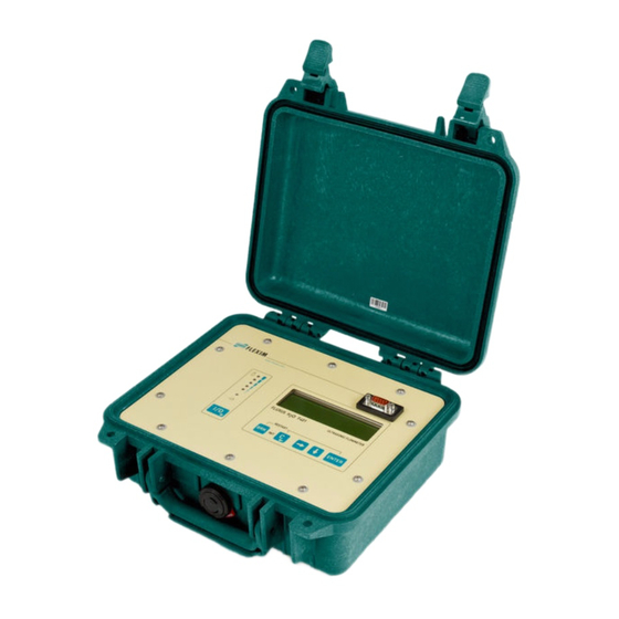
The command panel can be accessed by opening the cover. RS232 interface status indicator "charge state" status indicator 2 x16-digit LCD display, "power supply" backlit keyboard Fig. 5.1: Command panel of the transmitter FLUXUS F401 output power supply transducers Fig. 5.2: Connections of the transmitter FLUXUS F401 UMFLUXUS_F4V1-3EN, 2017-07-17... -
Page 23: Status Indication
5 Description of the Transmitter FLUXUS F401 Status Indication The status indicators only light if the transmitter is switched on and the display light is ac- tivated. Tab. 5.1: Status indicator "power supply" LED flashes green transmitter is connected to the power supply; battery is charging... - Page 24 FLUXUS F401 5 Description of the Transmitter Tab. 5.5: Input of digits move the cursor to the right scroll through the digits above the cursor Move the cursor to the left. If the cursor is on the left margin: • an already edited value will be reset to the value which was stored previously •...
-
Page 25: Selection Of The Measuring Point
6 Selection of the Measuring Point FLUXUS F401 Selection of the Measuring Point The correct selection of the measuring point is crucial for achieving reliable measure- ment results and a high measurement accuracy. A measurement on a pipe is possible if •... - Page 26 FLUXUS F401 6 Selection of the Measuring Point Note! Even bubble-free fluids can form gas pockets when the fluid ex- pands, e.g., before pumps and after great cross-section extensions. Observe the notes in the following table: Tab. 6.1: Recommended transducer mounting position...
-
Page 27: Undisturbed Flow Profile
6 Selection of the Measuring Point FLUXUS F401 Tab. 6.1: Recommended transducer mounting position Free inlet or outlet pipe section: Select the measuring point at a pipe location where the pipe cannot run empty. correct: disadvantageous: correct: disadvantageous: Undisturbed Flow Profile Some flow elements (elbows, slide valves, valves, control valves, pumps, reducers, dif- fusers, etc.) distort the flow profile in their vicinity. - Page 28 FLUXUS F401 6 Selection of the Measuring Point Tab. 6.2: Recommended distance from disturbance sources; D – nominal pipe diameter at the measuring point, l – recommended distance between disturbance source and transducer position disturbance source: 90° elbow inlet: l ≥ 10 D outlet: l ≥...
-
Page 29: Selection Of The Measurement Arrangement Taking Into Account The Measuring Range And The Measuring Conditions
6 Selection of the Measuring Point FLUXUS F401 Selection of the Measurement Arrangement Taking into Account the Measuring Range and the Measuring Conditions Diagonal arrangement Reflection arrangement • wider flow velocity and sound speed • smaller flow velocity and sound speed... -
Page 30: Selection Of The Sound Beam Plane Near An Elbow
FLUXUS F401 6 Selection of the Measuring Point Selection of the Sound Beam Plane near an Elbow With vertical pipe orientation With horizontal pipe flow direction elbow plane elbow plane flow direction • The sound beam plane (see section • The sound beam plane (see section 4.3.1) has an angle of 90°... -
Page 31: Installation Of Fluxus F401
Fig. 7.1. power supply unit/ battery charging unit transducers outputs Fig. 7.1: Connections on the transmitter FLUXUS F401 7.2.1 Transducers Connection • Remove the protective cap from the transmitter. • Remove the protective cap from the transducer by pulling the knurled ring slightly back. - Page 32 FLUXUS F401 7 Installation of FLUXUS F401 protective cap with marking knurled ring pulling direction marking on the transmitter socket marking on the connector Fig. 7.2: Transducer connector Removal • Pull the knurled ring slightly back and remove the connector from the transmitter socket.
-
Page 33: Power Supply
7 Installation of FLUXUS F401 FLUXUS F401 Removal • Push the connector firmly against the transmitter. Turn the knurled ring to the right and remove the connector from the transmitter socket. • Screw the protective cap on the socket. Turn protective cap to the right in order to fix it. -
Page 34: Connection Of The Outputs
FLUXUS F401 7 Installation of FLUXUS F401 Storage of the Battery The battery remains in the transmitter. After storage, the transmitter can immediately be operated with the battery. • charge state: > 30 % • storing temperature: 12...25 °C Connection of the Outputs For the connection of the outputs, see Fig. -
Page 35: Connection Of The Serial Interface Rs232
7 Installation of FLUXUS F401 FLUXUS F401 Fig. 7.4: Terminal assignment for the connection of the outputs Tab. 7.2: Terminal assignment for the connection of the outputs terminal connection A (+) binary output B1 B (-) binary output B1 C (+) -
Page 36: Connection Of The Serial Interface Rs485 (Optional)
FLUXUS F401 7 Installation of FLUXUS F401 Connection of the Serial Interface RS485 (optional) The RS485 interface is connected to the transmitter via the RS485 adapter, see Fig. 7.6. Fig. 7.6: RS485 adapter Tab. 7.3: Terminal assignment for the RS485 adapter... -
Page 37: Mounting Of The Transducers
8 Mounting of the Transducers FLUXUS F401 Mounting of the Transducers • Before you start this chapter, carry out the instructions in chapter 10. The transducers are fixed to the pipe by means of the supplied transducer mounting fix- ture. -
Page 38: Mounting Of The Transducers With Transducer Clamping Fixture And Ladder
FLUXUS F401 8 Mounting of the Transducers Mounting of the Transducers with Transducer Clamping Fixture and Ladder Chains • Insert the transducer into the transducer clamping fixture until it snaps. • Fix the chain to the hook of the transducer clamping fixture. -
Page 39: Mounting Of The Transducers With Transducer Shoe And Ball Chains
8 Mounting of the Transducers FLUXUS F401 Mounting of the Transducers with Transducer Shoe and Ball Chains • Insert the transducer into the transducer shoe. Turn the screw on the upper side of the transducer shoe by 90° in order to engage and lock its extremity in the groove on top of the inserted transducer. -
Page 40: Mounting Of The Transducers With Transducer Shoes And Ladder Chains
FLUXUS F401 8 Mounting of the Transducers Mounting of the Transducers with Transducer Shoes and Ladder Chains • Adjust the transducer distance on the ruler before installation of the transducer shoes. • Place the transducer shoes on the pipe at the measuring point. -
Page 41: Start-Up Of The Transmitter
9 Start-Up of the Transmitter FLUXUS F401 Start-Up of the Transmitter Start-up settings When starting up the transmitter for the first time, the following settings are required: • language • units of measurement • time/date These displays will only be indicated once when the transmitter is switched on for the first time. -
Page 42: Switching On
FLUXUS F401 9 Start-Up of the Transmitter Switching On Press key I/O to switch on the transmitter. FLEXIM FLUXUS As soon as the transmitter is switched on, the serial num- F401 -XXXXXXX ber of the transmitter is displayed for a short time. -
Page 43: Display
9 Start-Up of the Transmitter FLUXUS F401 Display 9.4.1 Main Menu The main menu contains the following program branches: >PAR< mea opt sf • par (Parameter) Parameter • mea (Measuring) • opt (Output Options) • sf (Special Functions) The selected program branch is displayed in capital letters between arrows. The com- plete designation of the selected program branch is displayed in the lower line. - Page 44 FLUXUS F401 9 Start-Up of the Transmitter For an overview of the program branches see figure below. For a detailed overview of the menu structure see annex A. Parameter Measuring Output Options Special Funct. >PAR< >MEA< >OPT< >SF< ↓ ↓...
-
Page 45: Hotcodes
9 Start-Up of the Transmitter FLUXUS F401 9.4.3 Navigation If a vertical arrow ↕ is displayed, the menu item contains a scroll list. The current list item is displayed in the lower line. Press key to scroll and select a list item in Volume in: ↕... -
Page 46: Language Selection
FLUXUS F401 9 Start-Up of the Transmitter Select Special Funct.\SYSTEM settings\Miscel- SYSTEM settings↕ laneous. Miscellaneous Select yes to enter a HotCode. Input a HOTCODE >YES< Enter the HotCode. Press ENTER. Please input a HOTCODE: 000000 An error message will be displayed if an invalid HotCode INVALID HOTCODE... -
Page 47: Basic Measurement
10 Basic Measurement FLUXUS F401 Basic Measurement The pipe and fluid parameters are entered for the selected measuring point (see chapter 6). The parameter ranges are limited by the technical characteristics of the transducers and the of transmitter. Note! The parameters will only be stored when the program branch... - Page 48 FLUXUS F401 10 Basic Measurement 10.1.3 Pipe Material The pipe material has to be selected to be able to determine the sound speed. The sound speed for the materials in the scroll list are stored in the transmitter. Select the pipe material.
-
Page 49: Input Of The Fluid Parameters
10 Basic Measurement FLUXUS F401 10.1.5 Pipe Roughness The flow profile of the fluid is influenced by the roughness of the inner pipe wall. The roughness is used for the calculation of the profile correction factor. As, in most cases, the pipe roughness cannot be determined exactly, it has to be estimated. -
Page 50: Input Of The Measuring Point Number
FLUXUS F401 10 Basic Measurement 10.4 Input of the Measuring Point Number Select the program branch Measuring. Press ENTER. par >MEA< opt sf Measuring If this error message is displayed, the parameters are not par >MEA< opt sf complete. Enter the missing parameters in the program NO DATA! branch Parameter. - Page 51 10 Basic Measurement FLUXUS F401 10.6.1 Fine Adjustment of the Transducer Distance If the displayed transducer distance is adjusted, press EN- Transd. Distance TER. 53.9 mm ! The measuring for the positioning of the transducers is started. The amplitude of the received signal is displayed by the S=■...
- Page 52 FLUXUS F401 10 Basic Measurement The optimum transducer distance is calculated on the basis of the measured sound speed. It is therefore a better approximation than the first recommended value which had been calculated on the basis of the sound speed range entered in the program branch Parameter.
-
Page 53: Start Of The Measurement
10 Basic Measurement FLUXUS F401 10.7 Start of the Measurement The measured values are displayed in the lower line. Volume flow Press ENTER to return to the fine adjustment of the trans- 31.82 m3/h ducer distance (see section 10.6.1). The outputs continuously receive the measured values of the corresponding channel. -
Page 54: Displaying The Measured Values
FLUXUS F401 11 Displaying the Measured Values Displaying the Measured Values The physical quantity is set in the program branch Output Options (see section 11.1). During the measurement, the designation of the physical quantity is displayed in the up- per line, the measured value in the lower line. The display can be adapted (see section 11.2). -
Page 55: Adjustment Of The Display
11 Displaying the Measured Values FLUXUS F401 11.2 Adjustment of the Display During the measurement, the display can be adapted as to display two measured values simultaneously (one in each line of the display). This does not affect totalizing, transmis- sion of the measured values, etc. - Page 56 FLUXUS F401 11 Displaying the Measured Values value explanation signal amplitude 0 < 5 % … … ≥ 90 % signal quality 0 < 5 % … … ≥ 90 % sound speed Comparison of the measured and the expected sound speed of the fluid.
-
Page 57: Transducer Distance
11 Displaying the Measured Values FLUXUS F401 11.4 Transducer Distance By pressing key during the measurement, it is possi- L=(51.2) 50.8 mm ble to scroll to the display of the transducer distance. 54.5 m3/h The optimum transducer distance (here: 51.2 mm) will be displayed in parentheses in the upper line, followed by the entered transducer distance (here: 50.8 mm). -
Page 58: Advanced Measuring Functions
FLUXUS F401 12 Advanced Measuring Functions Advanced Measuring Functions 12.1 Command Execution during Measurement Commands that can be executed during a measurement are shown in the upper line. A command begins with →. If programmed, a program code has to be entered (see sec- tion 12.7). -
Page 59: Totalizer
12 Advanced Measuring Functions FLUXUS F401 12.3 Totalizer The total volume and total mass of the fluid at the measuring point can be determined. There are 2 totalizers, one for the positive flow direction, one for the negative flow direc- tion. -
Page 60: Upper Limit Of The Flow Velocity
FLUXUS F401 12 Advanced Measuring Functions If on is selected, the values of the totalizers will be stored Quantity recall and used for the next measurement. >ON< If off is selected, the totalizers will be reset to zero. 12.3.1 Overflow of the Totalizers... -
Page 61: Cut-Off Flow
12 Advanced Measuring Functions FLUXUS F401 The upper limit of the flow velocity is set in Special Funct.\SYSTEM settings\Mea- suring\Velocity limit. Enter 0 (zero) to switch off the checking for outliers. Velocity limit Enter a limit > 0 to switch on the checking for outliers. The measured flow velocity will then be compared to the en- tered upper limit. -
Page 62: Uncorrected Flow Velocity
FLUXUS F401 12 Advanced Measuring Functions If Cut-off Flow\sign and user are selected, two values will have to be entered: Enter the cut-off flow. Press ENTER. +Cut-off Flow All positive values of the flow velocity that are lower than cm/s this limit will be set to zero. -
Page 63: Program Code
12 Advanced Measuring Functions FLUXUS F401 If yes is selected, the uncorrected flow velocity will only be PROFILE CORR. used if the flow velocity is selected as the physical quantity >YES< in the program branch Output Options. All other physical quantities (volumetric flow rate, mass flow, etc.) will be determined with the corrected flow velocity. - Page 64 FLUXUS F401 12 Advanced Measuring Functions 12.7.2 Intervention in the Measurement If a program code is active, the message PROGRAM CODE ACTIVE will be displayed for a few seconds when a key is pressed. The input of a program code is interrupted by pressing key C.
-
Page 65: Diagnosis With By Means Of The Snap Function
12 Advanced Measuring Functions FLUXUS F401 12.8 Diagnosis with by means of the Snap Function With the aid of the snap function it is possible to store measuring parameters which are useful for the evaluation of measuring results or for diagnostic purposes. -
Page 66: Data Logger And Transmission Of Data
FLUXUS F401 13 Data Logger and Transmission of Data Data Logger and Transmission of Data The transmitter has a data logger in which the measured values are stored during the measurement (see section 13.1). The measured values are transmitted to a PC via the serial interface directly during the measurement (see section 13.2). - Page 67 13 Data Logger and Transmission of Data FLUXUS F401 13.1.2 Setting the Storage Rate The storage rate is the frequency at which the measured values are transmitted or stored. If the storage rate is not set, the storage rate which was selected previously will be used.
- Page 68 FLUXUS F401 13 Data Logger and Transmission of Data Storage Mode Select the storage mode. Press ENTER. Storage mode If sample is selected, the displayed measured >SAMPLE< average value will be used for storing and online transmission of data.
- Page 69 13 Data Logger and Transmission of Data FLUXUS F401 13.1.4 Measurement with Activated Data Logger • Start the measurement. Enter the measuring point number. Press ENTER. Meas.Point No.: If arrows are displayed in the lower line on the right, ASCII xxx (↑↓←...
-
Page 70: Transmission Of Data
FLUXUS F401 13 Data Logger and Transmission of Data The time at which the data logger will be full, will be displayed during the measurement. All activated channels, totalizers and other values will be considered. Press key to scroll through the display of the upper full= 26.01/07:39... - Page 71 13 Data Logger and Transmission of Data FLUXUS F401 Selection of the Serial Interface for the Offline Transmission of Data Select Special Funct.\SYSTEM settings\serial transmis. Press ENTER until Send Offline via is displayed. Select the serial interface for the offline transmission of Send Offline via...
- Page 72 FLUXUS F401 13 Data Logger and Transmission of Data RS485 • default: 9600 bits/s, 8 data bits, even parity, 1 stop bit The transmission parameters for the RS485 interface can be changed in the program branch Special Funct.\SYSTEM settings\Network. This display will only be in- dicated if the transmitter has an RS485 interface.
- Page 73 13 Data Logger and Transmission of Data FLUXUS F401 • Set the storage rate (see section 13.1.2). • Start the measurement. The measuring point number will be requested (see section 13.1.4). The measured values are transmitted during the measure- SEND ONLINE-HEAD...
- Page 74 Offline Transmission of Data with the Program FluxData The measurement data in the data logger are transmitted to a PC via the serial interface RS232 with the FLEXIM program FluxData. Settings in the Program Start the program FluxData V3.0 or higher on the PC.
- Page 75 13 Data Logger and Transmission of Data FLUXUS F401 Transmission of Data Select the menu: DUT > Receive measuring val- ues. Wait until the data are transmit- ted. Stop of the Transmission of Data Select the menu: File > Save.
- Page 76 FLUXUS F401 13 Data Logger and Transmission of Data 13.2.8 Structure of the Data The header is transmitted at the beginning of the measurement. The first 4 lines contain general information about the transmitter and the measurement. The following lines con- tain the parameters of each channel.
- Page 77 13 Data Logger and Transmission of Data FLUXUS F401 In every storage interval, one data line per activated measuring channel is transmitted. The line "???" will be transmitted if there are no measured values available for the stor-- age interval.
-
Page 78: Settings
FLUXUS F401 14 Settings Settings 14.1 Time and Date The transmitter has a battery-powered clock. 14.1.1 Time Select Special Funct.\SYSTEM settings\Set SYSTEM settings↕ Clock. Press ENTER. Set Clock The current time is displayed. Select ok to confirm the time TIME 11:00... - Page 79 14 Settings FLUXUS F401 14.2.1 Pipe Circumference Select on if the pipe circumference is to be entered instead Pipe Circumfer. of the pipe diameter in the program branch Parameter. >ON< Press ENTER. If on is selected for Pipe Circumfer., the outer pipe di- Outer Diameter...
- Page 80 FLUXUS F401 14 Settings 14.2.3 Transducer Distance recommended setting: user Transd. Distance • user will be selected if the measuring point is always the auto >USER< same. • auto can be selected if the measuring point changes of- ten. In the program branch Measuring, the recommended Transd.
- Page 81 14 Settings FLUXUS F401 Select °C or °F as the unit of measurement for the tem- Temperature perature. Press ENTER. >[°C]< [°F] Select bar or psi as the unit of measurement for the pres- Pressure sure. Press ENTER. >[bar]< [psi]...
-
Page 82: Measurement Settings
FLUXUS F401 14 Settings 14.3 Measurement Settings Select Special Funct.\SYSTEM settings\Measur- SYSTEM settings↕ ing. Press ENTER. Measuring Note! The settings will be stored at the end of the dialog. If the menu item is quit by pressing key BRK, the changes will not be stored. -
Page 83: Setting The Contrast
14 Settings FLUXUS F401 14.4 Setting the Contrast Select Special Funct.\SYSTEM settings\ Miscel- SYSTEM settings↕ laneous to set the contrast of the display of the transmit- Miscellaneous ter. Press ENTER. The contrast of the display is adjusted with the following SETUP DISPLAY... -
Page 84: Superuser-Modus
FLUXUS F401 15 SuperUser-Modus SuperUser-Modus The SuperUser mode offers the possibility of an advanced analysis of the signal and the measured values as well as the definition of additional parameters adapted to the mea- suring point, in order to achieve better measuring values or during experimental work. - Page 85 15 SuperUser-Modus FLUXUS F401 15.2.1 Profile Bounds Select user if the profile bounds are to be defined. If fac- Profile bounds tory is selected, the default profile bounds will be used factory >USER< and the menu item Calibration will be displayed (see section 15.2.2).
- Page 86 FLUXUS F401 15 SuperUser-Modus 15.2.2 Correction of the Flow Velocity After the profile bounds have been defined (see section 15.2.1), it is possible to define a correction of the flow velocity. v + n with – measured flow velocity –...
-
Page 87: Limit Of The Signal Amplification
15 SuperUser-Modus FLUXUS F401 Attention! The correction of the flow velocity is still active after the deactivation of the SuperUser mode. 15.3 Limit of the Signal Amplification In order to prevent disturbing and/or pipe wall signals (e.g., if the pipe has run empty) from being interpreted as useful signals, it is possible to define a max. -
Page 88: Detection Of Long Measurement Failures
FLUXUS F401 15 SuperUser-Modus Enter for each measuring channel the fixed upper limit of Bad soundspeed the sound speed. Enter 0 (zero) to use the default value thresh. 2007 m/s 1 848 m/s. Press ENTER. Enter for each measuring channel the offset. Enter 0 (zero) Bad soundspeed... -
Page 89: Number Of Decimal Places Of The Totalizers
15 SuperUser-Modus FLUXUS F401 15.6 Number of Decimal Places of the Totalizers The totalizer values can be displayed with up to 11 places, e.g., 74890046.03. In the SuperUser mode, it is possible to define the number of decimal places. Select Special settings\Measuring\Miscellaneous. -
Page 90: Manual Reset Of The Totalizers
FLUXUS F401 15 SuperUser-Modus 15.7 Manual Reset of the Totalizers If the manual reset of the totalizers is activated, the totalizers can also be reset to zero during the measurement by pressing key C 3 times, even if a program code is activated. -
Page 91: Display During The Measurement
15 SuperUser-Modus FLUXUS F401 15.10 Display During the Measurement In the SuperUser mode, the following parameters can be displayed during the measure- ment besides the normal information (see section 11.2): display meaning transit time of the measuring signal sound speed... -
Page 92: Outputs
FLUXUS F401 16 Outputs Outputs If the transmitter is equipped with outputs, they have to be installed and activated before they can be used: • assign the physical quantity (source item) to be transmitted to the output by the source channel, and the properties of the signal •... - Page 93 16 Outputs FLUXUS F401 The source items and their scroll lists are described in Tab. 16.1. Tab. 16.1: Configuration of the outputs source item list item output physical quantity selected in the program Measuring branch Output Options value totalizer for the positive flow direction...
- Page 94 FLUXUS F401 16 Outputs 16.1.2 Error Value In the following dialog, an error value can be defined which is to be transmitted if the source item cannot be measured, e.g., if there are gas bubbles in the fluid. Tab. 16.2: Error output...
- Page 95 16 Outputs FLUXUS F401 Tab. 16.3: Examples for the error output list item for the output signal error output I [ m A ] Error-value ↕ Minimum (4.0mA) Error-value ↕ I [ m A ] Hold last value Error-value ↕...
- Page 96 FLUXUS F401 16 Outputs Select a list item for the error output. Press ENTER. Error-value ↕ Minimum (4.0mA) If Other value is selected, enter an error value. It has to Error-value be within the limits of the output. Press ENTER.
-
Page 97: Error Value Delay
16 Outputs FLUXUS F401 Select yes to repeat the test, no to return to SYSTEM B1=ON settings. Press ENTER. Again? no >YES< 16.2 Error Value Delay The error value delay is the time interval after which the entered value for the error value is transmitted to the output in case no valid measured values are available. - Page 98 FLUXUS F401 16 Outputs Enter the highest expected measured value. Full-Scale Val. Full-Scale Val. is the measured value corresponding 300.00 m3/h to the upper limit of the output range as defined in section 16.1.1. Example: output: current output output range: 4…20 mA...
-
Page 99: Activation Of A Binary Output As A Pulse Output
16 Outputs FLUXUS F401 16.4 Activation of a Binary Output as a Pulse Output A pulse output is an integrating output which emits a pulse when the volume or the mass of the fluid which has passed the measuring point reaches a given value (Pulse Val- ue). - Page 100 FLUXUS F401 16 Outputs 16.5.1 Alarm Properties The switching condition, the holding behavior and the switching function of an alarm out- put can be defined. Three scroll lists will be displayed: R1=FUNC<typ mode • func: switching condition Function: • typ: holding behavior •...
- Page 101 16 Outputs FLUXUS F401 16.5.2 Setting the Limits If the switching condition MAX or MIN is selected in the scroll list func, the limit of the out- put will have to be defined: Select in the scroll list Input the physical quantity to be R1 Input: ↕...
- Page 102 FLUXUS F401 16 Outputs If the switching condition QUANT. is selected in the scroll list func, the limit of the output will have to be defined: switching condition: QUANT. Quantity Limit: Enter the limit of the totalizer. Press ENTER. 1.00 The alarm will switch if the measured value reaches the limit.
-
Page 103: Behavior Of The Alarm Outputs
16 Outputs FLUXUS F401 switching condition: MIN or MAX R1 Hysterese: Enter the value for Hysterese. 1.00 m3/h Enter 0 (zero) to work without a hysteresis. Press ENTER. 16.6 Behavior of the Alarm Outputs 16.6.1 Apparent Switching Delay The measured values and the totalizer values will be displayed rounded to 2 decimal places. - Page 104 FLUXUS F401 16 Outputs 16.6.4 Alarm Outputs during Measurement An alarm output with switching condition MAX or MIN will be updated max. once per sec- ond to avoid humming (i.e. fluctuation of the measured values around the value of the switching condition).
- Page 105 16 Outputs FLUXUS F401 16.6.5 Alarm State Indication Note! There is no visual or acoustic indication of alarm output switching. The alarm state can be displayed during the measurement. This function is activated in Special Funct.\SYSTEM settings\Dialogs/Menus. The activation of this function is recommended when alarm outputs have to be reconfigured frequently.
-
Page 106: Deactivation Of The Alarm Outputs
FLUXUS F401 16 Outputs Tab. 16.6: Pictograms for the alarm state indication typ current state func mode (switching condition) (holding behavior) (switching function) R1 = closed NON-HOLD NO Cont. open HOLD NC Cont. +→- -→+ QUANT. ERROR Example: R1 = 16.7... -
Page 107: Troubleshooting
Check that the battery is inserted and charged. Connect the power supply. If the power supply is ok, the transducers or an internal component of the transmitter are defective. The transducers and the transmitter have to be sent to FLEXIM for repair. The message "System Error" is displayed Press key BRK to return to the main menu. -
Page 108: Problems With The Measurement
FLUXUS F401 17 Troubleshooting 17.1 Problems with the Measurement A measurement is impossible because no signal is received. A question mark is displayed in the lower line on the right • Check if the entered parameters are correct, especially the outer pipe diameter, the pipe wall thickness and the sound speed of the fluid. -
Page 109: Selection Of The Measuring Point
17 Troubleshooting FLUXUS F401 17.2 Selection of the Measuring Point • Make sure that the recommended min. distance to any disturbance source is observed (see chapter 6, Tab. 6.2). • Avoid measuring points with deposit formation in the pipe. • Avoid measuring points in the vicinity of deformations and defects on the pipe and in the vicinity of welds. -
Page 110: Large Deviations Of The Measured Values
The flow is in the transition range between laminar and turbulent flow where flow measurement is difficult Calculate the Reynolds number of the flow at the measuring point with the program Flux- Flow (free download: www.flexim.com). Contact FLEXIM. 17.5 Large Deviations of the Measured Values... -
Page 111: Problems With The Totalizers
17 Troubleshooting FLUXUS F401 17.6 Problems with the Totalizers The values of the totalizers are too high See Special Function\SYSTEM settings\Measuring\Quantity recall. If this menu item is activated, the values of the totalizer will be stored. The totalizer will con- tinue with this value at the start of the next measurement. -
Page 112: A Menu Structure
FLUXUS F401 A Menu Structure Menu Structure Annex INIT- resistant Program branch Parameter main menu: selection of the program branch >PAR< mea opt sf Parameter Parameter input of the outer pipe diameter Outer Diameter 100.0 input of the pipe circumference Pipe Circumfer.... - Page 113 A Menu Structure FLUXUS F401 INIT- resistant input of the liner thickness Liner Thickness range: 0...50 mm default: 3 mm input of the roughness of the inner pipe wall Roughness range: 0...5 mm default: 0.1 mm (for steel as pipe material) input of the fluid temperature Medium Temperat....
- Page 114 FLUXUS F401 A Menu Structure INIT- resistant Program branch Output Options main menu: selection of the program branch par mea >OPT< sf Output Options Output Options selection of the physical quantity Physic. Quant. ↕ Volume flow selection of the unit of measurement for the Volume in: ↕...
- Page 115 A Menu Structure FLUXUS F401 INIT- resistant input of the lowest/highest measured value to Zero-Scale Val. be expected for the current output 0.00 m3/h The values are assigned to the lower/upper limit of the output range. Full-Scale Val. These displays will only be indicated if Cur- 300.00...
- Page 116 FLUXUS F401 A Menu Structure INIT- resistant Selection of the switching condition (func), the R1=FUNC<typ mode holding behavior (typ) and the switching func- Function: tion (mode) of the alarm output. This display will only be indicated if Alarm Output is activated.
- Page 117 A Menu Structure FLUXUS F401 INIT- resistant SYSTEM settings\Set Clock selection of the displays for the input of the SYSTEM settings↕ date and the time Set Clock SYSTEM settings\Dialogs/Menus selection of the displays for the activation/de- SYSTEM settings↕ activation or setting of the menu items in the...
- Page 118 FLUXUS F401 A Menu Structure INIT- resistant selection of the unit of measurement for the Temperature temperature >[°C]< [°F] selection whether the absolute pressure p Pressure absolut relative pressure p is to be used >ON< selection of the unit of measurement for the Pressure...
- Page 119 A Menu Structure FLUXUS F401 INIT- resistant activation of the input of a lower limit of the flow Cut-off Flow velocity: factory >USER< • factory: the default limit of 2.5 cm/s will be used • user: input of a limit input of the cut-off flow for positive measured +Cut-off Flow...
- Page 120 FLUXUS F401 A Menu Structure INIT- resistant input of the offset Bad soundspeed range: 0...900 m/s offset: +321 m/s 0: the default limit of 300 m/s will be used This display will only be indicated if the SuperUser mode is activated.
- Page 121 A Menu Structure FLUXUS F401 INIT- resistant activation of the turbulence mode Turbulence mode >ON< Special Funct.\SYSTEM settings\Measuring\Calibration determination of the profile bounds Profile bounds factory: the default profile bounds will be used factory >USER< user: the profile bounds can be defined This display will only be indicated if the ...
- Page 122 FLUXUS F401 A Menu Structure INIT- resistant Input of the offset. Offset= range: -12.7…+12.7 cm/s 0.0 cm/s 0: without offset This display will only be indicated if the SuperUser mode is activated and Calibration = on is selected. SYSTEM settings\Proc. outputs selection of the displays for the transmitter out- SYSTEM settings↕...
- Page 123 A Menu Structure FLUXUS F401 INIT- resistant activation of the fluid sound speed storing Store c-Medium The value will only be stored if the data logger >ON< is activated. activation of storing of the diagnostic values Store diagnostic >ON< SYSTEM settings\Miscellaneous selection of the display for the contrast setting SYSTEM settings↕...
- Page 124 FLUXUS F401 A Menu Structure INIT- resistant input of the break code (= program code) INPUT BREAK_CODE CODE: 000000 input of the access code (= the first three digits INP. ACCESS CODE of the program code) CODE: 000000 UMFLUXUS_F4V1-3EN, 2017-07-17...
-
Page 125: B Units Of Measurement
B Units of Measurement FLUXUS F401 Units of Measurement Length/roughness Temperature unit of measurement description unit of measurement description millimeter °C degree Celsius inch inch °F degree Fahrenheit Pressure unit of measurement description bar(a) bar (absolute) bar(g) bar (relative) psi(a) - Page 126 FLUXUS F401 B Units of Measurement flow velocity unit of measurement. description meter per second cm/s centimeter per second in/s inch per second fps (ft/s) foot per second Volumetric flow rate Volume (totalized) unit of unit of measurement description...
- Page 127 B Units of Measurement FLUXUS F401 Volumetric flow rate Volume (totalized) unit of unit of measurement description measurement bbl/d barrel per day bbl/h barrel per hour bbl/m barrel per minute USgpd (US-gal/d) gallon per day USgph (US-gal/h) gallon per hour...
- Page 128 FLUXUS F401 B Units of Measurement Mass flow rate Mass (totalized) unit of description unit of measurement measurement metric ton per hour metric ton per day kg/h kilogram per hour kg/min kilogram per minute kg/s kilogram per second gram per second...
- Page 129 B Units of Measurement FLUXUS F401 Flow Nomogram (Metrical) volumetric flow rate volumetric flow rate V o l u m e n f l u s s V o l u m e n f l u s s 1 0 0...
- Page 130 FLUXUS F401 B Units of Measurement Flow Nomogram (imperial) volumetric flow rate volumetric flow rate V o l u m e n f l u s s V o l u m e n f l u s s 1 0 0...
-
Page 131: C Reference
Reference The following tables provide assistance for the user. The accuracy of the data depends on the composition, temperature and processing of the material. FLEXIM does not as- sume liability for any inaccuracies. Sound Speed of Selected Pipe and Lining Materials at 20 °C The values of some of these materials are stored in the internal database of the transmit- ter. - Page 132 FLUXUS F401 C Reference Typical Roughnesses of Pipes The values are based on experience and measurements. material absolute roughness [mm] drawn pipes of non-ferrous metal, glass, plastics and 0…0.0015 light metal drawn steel pipes 0.01…0.05 fine-planed, polished surface max. 0.01 planed surface 0.01…0.04...
- Page 133 C Reference FLUXUS F401 Properties of Water at 1 bar and at Saturation Pressure fluid temperature fluid pressure sound speed density specific heat [°C] [bar] [m/s] [kg/m capacity* [kJ/kg/K 1,013 1402.9 999.8 4,219 1,013 1447.3 999.7 4,195 1,013 1482.3 998.2...
-
Page 134: D Conformity Declarations
FLUXUS F401 D Conformity Declarations Conformity Declarations UMFLUXUS_F4V1-3EN, 2017-07-17...
Need help?
Do you have a question about the FLUXUS F401 and is the answer not in the manual?
Questions and answers