Table of Contents
Advertisement
Manual MVK-MP
Manual for MVK-MP Modules
For Use with GSD Version 1 and HW/SW Version 1
Art.-No. 55274, MVK-MP DO4 (DO4) DI4 (DI4)
Art.-No. 55290, MVK-MP DO8 (DO8)
Art.-No. 55291, MVK-MP K3 DO4 (DO4) / DIO4 (DIO4)
Art.-No. 55292, MVK-MP AO4 (I) DIO4 (DIO4)
Art.-No. 55293, MVK-MP AI4 (U) DIO4 (DIO4)
Art.-No. 55307, MVK-MP DI8 (DI8)
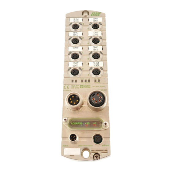
Art.-No. 55308, MVK-MP DIO8 (DI8)
Art.-No. 55309, MVK-MP DIO8 (DIO8)
Imprint
Manual for MVK-MP Module, Article No. 55393
Version 3.5
Effective date 2019-07
Murrelektronik GmbH
Falkenstraße 3
71570 Oppenweiler
GERMANY
Fon +49 7191 47-0
Fax +49 7191 47-491000
info@murrelektronik.com
V 3.5
1
Advertisement
Table of Contents

Related Manuals for Murr Elektronik 55308


Summarization of Contents
Important Information
Explanation of Symbols
Explains symbols used in the manual for safety and information.
Designated Use
Details the intended use of the MVK-MP modules in industrial environments.
Configuration
Power Supply
Covers requirements and recommendations for powering the MVK-MP modules.
Electromagnetic Compatibility (EMC)
Discusses EMC requirements and installation guidelines for compliance.
Replaceability
Explains the downward compatibility and replacement of MVK-MP modules.
Installation
Assembly
Details the procedure and requirements for physically mounting the modules.
Functional Earth
Describes the connection and importance of functional earth for module safety.
Connection Overview
Provides pin assignments and connection diagrams for various MVK-MP modules.
Connection of Digital Sensors and Actuators
Explains how to connect digital sensors and actuators to the modules.
Connection of Analog Sensors
Details how to connect analog sensors to the modules.
Connection of the Profibus
Covers Profibus cable connection and termination resistor requirements.
Connection of Supply Voltage
Explains how to connect the supply voltage and precautions.
Setup
Assigning and Setting the Profibus Address
Details how to set the Profibus address using BCD switches.
GSD File
Explains the role and availability of the GSD file for configuration.
Configuration
Discusses the Profibus DP slave configuration and virtual modules.
Parameterization
Explains the parameter message structure and settings.
Diagnostic
LED General Information
Explains the meaning of the Bus Run LED and diagnostic LEDs.
LED Display
Details the relationship between errors, LED indicators, and module types.
Structure of a Diagnostic Message
Explains the structure of diagnostic messages, including standard and manufacturer-specific info.
Technical Data
Mechanical data
Details the physical dimensions, materials, and environmental ratings.
Electrical data
Presents detailed electrical specifications for various modules.
Need help?
Do you have a question about the 55308 and is the answer not in the manual?
Questions and answers