Table of Contents
Advertisement
Advertisement
Table of Contents

Related Manuals for Murr Elektronik Cube67 Series


Summary of Contents for Murr Elektronik Cube67 Series
- Page 1 Handbuch Manual Manuel Cube67...
- Page 2 System Manual For Modules Of The Cube67 Series - For use in combination with SW Version 2.xx - User Manual Art. No. 56 970 Version 2.5 Murrelektronik GmbH Postfach 1165 71567 Oppenweiler Phone ++49 7191 47-0 Falkenstrasse 3 71570 Oppenweiler Telefax ++49 7191 47-130 Internet : http://www.murrelektronik.com...
-
Page 4: Table Of Contents
Cube67 System Manual Table of Contents ABOUT THIS MANUAL .................... Chapter Overview ........................... 6 SAFETY INSTRUCTIONS ..................7 Designated Use ..........................7 Qualified Personnel ........................8 Explanation of Symbols ......................... 9 2.3.1 Use of Attention Signs ......................9 2.3.2 Use of Danger Signs ......................... 9 2.3.3 Use of Numbering in Illustrations .................... - Page 5 Cube67 System Manual 3.4.5.2 Connecting Sensors/Actuators with Diagnostic Output............. 28 3.4.5.3 Monitoring a Line for Line Breaks ..................29 Electromagnetic Compatibility (EMC) ..................29 3.5.1 Protection Against Electrostatic Discharge ................ 30 3.5.2 Grounding ..........................31 3.5.3 Cable Routing ......................... 31 3.5.4 Voltage Drops .........................
- Page 6 Cube67 System Manual Manual Revisions Version Chapter Additions / Corrections Date/Name Issued by 24.04.03 / Hinze Ch. 4 New modules 28.08.03 / Grofik 56740 new 04.12.03 / Grofik (10 m per branch) 15.04.04 / Hinze 4.1.7 / 4.2.2 1.31 Ch. 4.2 2 17.08.04 / Eberhard Ch.
-
Page 7: About This Manual
The text, illustrations, diagrams and examples presented in this manual serve solely for the purpose of explanation, operation and use of Input/Output modules of the Cube67 series. If you should have any further reaching questions regarding the installation and setup of the equipment described in this manual, please do not hesitate to contact us. -
Page 8: Safety Instructions
Cube67 System Manual 2 Safety Instructions Designated Use The devices described in this manual are decentralized input/output modules intended for connection to a field bus network. The products described in this manual • have been developed, manufactured, tested, and documented in compliance with the relevant standards. -
Page 9: Qualified Personnel
Cube67 System Manual Qualified Personnel Requirements to be met by qualified personnel are based on qualification profiles described in ZVEI and VDMA guidelines. Weiterbildung in der Automatisierungstechnik (Further training in automation technology) Herausgeber: ZVEI und VDMA (Publisher: ZVEI and VDMA) Maschinenbau Verlag Postfach 71 08 64 60498 Frankfurt... -
Page 10: Explanation Of Symbols
Cube67 System Manual Explanation of Symbols 2.3.1 Use of Attention Signs Notes containing important information are specially marked. These are illustrated as follows : Attention text..2.3.2 Use of Danger Signs Danger signs are additionally marked with a surrounding border. CAUTION: Disregard of safety measures may result in damage to equipment and other serious consequences. -
Page 11: The Cube67 System
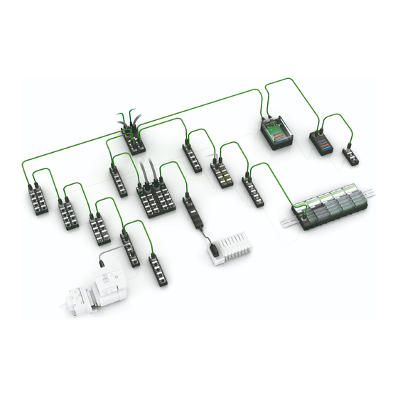
Cube67 System Manual 3 The Cube67 System Fig. 3-1 : The Cube67 System The Cube67 System is a tailor-made solution designed for decentralized applications in automation systems. This innovative system offers new possibilities: Cost-effective decentralization..distributed, modular, compact ,and robust design. ... -
Page 12: System Components
Cube67 System Manual Configuration Notes This chapter contains a brief description of the Cube67 System components and information relevant to the electromechanical planning phase. ♦ Product designation ♦ Components ♦ Topology ♦ Permissible cable lengths ♦ Current-carrying capacity ♦ Power supply requirements System Components 3.1.1 Product Designation... -
Page 13: Bus Node
Cube67 System Manual 3.1.2 Bus Node The task of the Cube67 System is to combine decentrally the signals of the I/O level and provide this information over the field bus network (e.g. PROFIBUS). The central unit is the bus node, which interconnects the Cube67 I/O modules and the field bus. -
Page 14: Expander Modules
Cube67 System Manual 56 710 AO4 C 4xM12 (U) 56 720 AO4 C 4xM12 (I) 56 730 AI4 C 4xM12 (I) 56 740 AI4 C 4xM12 RTD 56 748 AI4 C 4xM12 TH 3.1.5 Expander Modules Expander modules are fitted out with an extension interface for the internal system connection, i.e. the latter can be routed to the following I/O modules. - Page 15 Cube67 System Manual Terminal Resistance of the Internal S). Table 3-3 : Expander modules Art. No. Designation 56 600 2 DO32 E Valve 0.5 A Cable 2m 56 601 DIO16 E 8xM12 56 605 DO12 E 6xM12 K3 56 611 DIO8 E 4xM12 56 621 DIO8 E 8xM8...
-
Page 16: Supplementary Modules
Cube67 System Manual 3.1.6 Supplementary Modules Supplementary modules have neither I/O functions, nor connection to the internal system connection. Diagnosis is only signaled by the LED indicators on the device. There is no diagnosis via the field bus. Table 3-4 : Supplementary modules Art. -
Page 17: Cube20 Modules
Cube67 System Manual 3.1.9 Cube20 Modules For information on Cube20 module, refer to the Cube20 manuals. 3.1.10 Customer-Specific Modules Customer-specific modules are modules which are based on a standard module and which are adapted to customer-specific solutions (e.g. different plug, cable length). Table 3-6 : Overview of customer-specific modules Art. -
Page 18: Internal System Connection - Hybrid Line
Cube67 System Manual Art. No. Designation 56 656 01 DO24 E Valve MPA 56 656 02 DO32 E Valve HF03 56 656 03 DO32 E Valve VM10 56 656 04 DO23 E Valve SMC 56 656 05 DO22 E Valve CPA 56 656 06 DO24 E Valve HF04 56 656 07... -
Page 19: External Power" Cables
Cube67 System Manual Length Art. No. straight-straight 90°-90° 8.0 m 7000-46041-8020800 7000-46061-8020800 8.5 m 7000-46041-8020850 7000-46061-8020850 9.0 m 7000-46041-8020900 7000-46061-8020900 9.5 m 7000-46041-8020950 7000-46061-8020950 10.0 m 7000-46041-8021000 7000-46061-8021000 Table 3-8 : Contact arrangement of the system connection Arrangement Contacts Meaning Actuator power supply Sensor power supply / internal module power supply Ground... -
Page 20: Preterminated 7/8" Power Cables
Cube67 System Manual 3.1.13 Preterminated 7/8“ Power Cables The Cube67 System is supplied with voltage via a 7/8" connector. The voltage supply for the sensors and actuators can be fed in separately. The ground of both supply voltages is connected internally. The operating voltage of the Cube67 components is drawn from the sensor power supply. -
Page 21: Current-Carrying Capacity
Cube67 System Manual 3.2.1 Current-Carrying Capacity The modules connected to the bus node are supplied with two voltages via the internal system connection. Table 3-11 : Current-carrying capacity Current-carrying Supply of capacity sensor power voltage Module electronics and sensors Internal actuator supply Actuators CAUTION: Make sure to avoid feedback of the sensor supply voltage caused by external... -
Page 22: Topology
Cube67 System Manual Table 3-12 : Overview of MICO variants Art. No. Designation Rated operating branch-circuit current (full load) 9000-41034-0100400 MICO 4.4 (4 channels) each 4 A 9000-41034-0100600 MICO 4.6 (4 channels) each 6 A 9000-41034-0401000 MICO 4.10 (4 channels) each 10 A 9000-41042-0100400 MICO 2.4 (2 channels) -
Page 23: Bus Node Used As Power Distributor
Cube67 System Manual 3.2.4 Bus Node Used As Power Distributor If some branches of the bus node internal system connection are not assigned, they can be used to supply consumers, provided that the maximum permissible current is within the limits. Please note that only the actuator power supply can be used in this case. -
Page 24: Terminal Resistance Of The Internal System Connection
Cube67 System Manual 3.2.6 Terminal Resistance of the Internal System Connection A terminal resistance must be installed on each branch of the internal system connection. Compact modules have an integrated terminal resistance. If the last I/O module in a branch is a compact module, it is not necessary to install a supplementary terminal resistance. -
Page 25: Power Supply
Cube67 System Manual Art. No. Designation 7000-14041-0000000 Terminating resistor M12 PROFIBUS (connector) 7000-13461-0000000 Terminating resistor M12 DeviceNet / CANopen (connector) 7000-13471-0000000 Terminating resistor M12 DeviceNet / CANopen (socket) 7002-15041-0000000 Terminating resistor M12 for the internal system connection (connector) 38 586 27 M8 PLASTIC SCREW PLUG VE 10 (dummy plug) 58 627 M12 PLASTIC SCREW PLUG VE 10 (dummy plug) -
Page 26: Recommended Power Supply Units Mcspower
Cube67 System Manual CAUTION: Sensors may only be supplied via the bus node in a Cube67 system. Feedback by sensors or an external power supply (in order to increase maximum current) is not permissible. 3.3.2 Recommended Power Supply Units MCSPower+ Primary-clocked power supply units of the MCSPower+ series are specially designed to supply systems in automation engineering. -
Page 27: Connecting Sensors And Actuators
Cube67 System Manual Connecting Sensors and Actuators 3.4.1 Sensor Power Supply Sensors can be supplied by the I/O module . One resettable PTC per M12 socket protects the sensor supply. The maximum current draw for the sensor power supply is 200 mA for each M12 socket. Please note the following derating diagram. -
Page 28: Supply Of External Modules (Art. No. 56 710 / 56 720)
Cube67 System Manual 3.4.2 Supply of External Modules (Art. No. 56 710 / 56 720) Analog output modules Art. Nos. 56 710 and 56 720 can be supplied via Pin 1 of the M12 socket by the actuator power supply (not switchable). When measuring the total current of 4 A for the whole branch, the maximum current draw per slot is 1.6 A. -
Page 29: Desina Diagnostic Input
Cube67 System Manual To increase power, outputs may be connected in parallel. If an overload or short-circuit occurs at an output, the output affected is disabled. This output remains disabled even after the fault is rectified. In order to reset the short- circuit memory, reset the output or switch off the actuator power supply. -
Page 30: Monitoring A Line For Line Breaks
Cube67 System Manual 3.4.5.3 Monitoring a Line for Line Breaks Murrelektronik GmbH supplies the M12 diagnostic adapter with a simple accessory that helps you to monitor M12 lines to the sensors or actuators of your system for line breaks. CAUTION: Do not connect a line with LED in the plug to a Desina sensor;... -
Page 31: Protection Against Electrostatic Discharge
Cube67 System Manual 3.5.1 Protection Against Electrostatic Discharge The products described in this manual contain complex semiconductor elements that can be destroyed or damaged by electrostatic discharges (ESD). Damage does not necessarily result in an immediately recognizable failure or malfunction. Failure or malfunctioning can occur with delayed effect or sporadically. -
Page 32: Grounding
Cube67 System Manual 3.5.2 Grounding A short and low impedance connection between the grounding terminal and ground is required to draw off interference voltages occurring between the device and ground. The inductance of conventional FE cables is a source of high impedance for high-frequency interference voltages. For this reason, the use of grounding strips is preferred. -
Page 33: Inductive Load Interference Suppression
Cube67 System Manual 3.5.6 Inductive Load Interference Suppression The outputs in the devices described in this manual feature an integrated surge protection circuit against interference voltage that arises when switching inductive devices. Inductive load Varistor (e.g. solenoid valve) The varistor ensures rapid dissipation of the energy stored in the magnetic field of the inductive load. The high voltages which occur when switching off inductive loads produce strong fields in the wiring. -
Page 34: Index Of Figures
Cube67 System Manual 4 Index of Figures Fig. 3-1 : The Cube67 System ........................10 Fig. 4-1 : Topology ............................21 Fig 4-2 : Use of the Cube67 PD 7/8” power distributor (example) ............. 22 Fig. 4-3 : Terminating the internal system connection (example) ............... 23 Fig. -
Page 35: Index Of Tables
Cube67 System Manual 5 Index of Tables Table 4-1 : Bus nodes ..........................12 Table 4-2 : Compact modules ........................12 Table 4-3 : Expander modules........................14 Table 4-4 : Supplementary modules ......................15 Table 4-5 : Overview of function modules ....................15 Table 4-6 : Overview of customer-specific modules ................... -
Page 36: Legal Provisions
Cube67 System Manual Legal Provisions Exclusion of Liability Murrelektronik GmbH has checked the contents of this technical documentation for conformity with the hardware and software described therein. Deviations can not be excluded in individual cases. For this reason, Murrelektronik excludes the warranty for the correctness of its contents and any liability for errors, in particular full conformity. - Page 37 Murrelektronik GmbH|Falkenstraße 3, D-71570 Oppenweiler|P.O. Box 1165, D-71567 Oppenweiler Phone +49 7191 47-0|Fax +49 7191 47-130|info@murrelektronik.com|www.murrelektronik.com The information in this manual has been compiled with the utmost care. Liability for the correctness, completeness and topicality of the information is restricted to gross negligence.
Need help?
Do you have a question about the Cube67 Series and is the answer not in the manual?
Questions and answers