Table of Contents
Advertisement
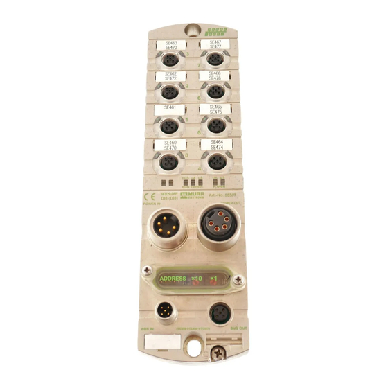
Manual MVK-MP
Manual for MVK-MP Modules
For Use with GSD Version 1 and HW/SW Version 1
Art.-No. 55274, MVK-MP DO4 (DO4) DI4 (DI4)
Art.-No. 55290, MVK-MP DO8 (DO8)
Art.-No. 55291, MVK-MP K3 DO4 (DO4) / DIO4 (DIO4)
Art.-No. 55292, MVK-MP AO4 (I) DIO4 (DIO4)
Art.-No. 55293, MVK-MP AI4 (U) DIO4 (DIO4)
Art.-No. 55307, MVK-MP DI8 (DI8)
Art.-No. 55308, MVK-MP DIO8 (DI8)
Art.-No. 55309, MVK-MP DIO8 (DIO8)
Imprint
Manual for MVK-MP Module, Article No. 55393
Version 3.5
Effective date 2019-07
Murrelektronik GmbH
Falkenstraße 3
71570 Oppenweiler
GERMANY
Fon +49 7191 47-0
Fax +49 7191 47-491000
info@murrelektronik.com
V 3.5
1
Advertisement
Table of Contents


Need help?
Do you have a question about the MVK-MP and is the answer not in the manual?
Questions and answers