Table of Contents
Advertisement
Manual MVK-MP
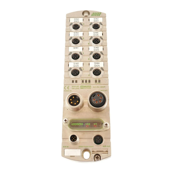
Manual for MVK-MP Modules
For Use with GSD Version 1 and HW/SW Version 1
Art.-No. 55274, MVK-MP DO4 (DO4) DI4 (DI4)
Art.-No. 55290, MVK-MP DO8 (DO8)
Art.-No. 55291, MVK-MP K3 DO4 (DO4) / DIO4 (DIO4)
Art.-No. 55292, MVK-MP AO4 (I) DIO4 (DIO4)
Art.-No. 55293, MVK-MP AI4 (U) DIO4 (DIO4)
Art.-No. 55307, MVK-MP DI8 (DI8)
Art.-No. 55308, MVK-MP DIO8 (DI8)
Art.-No. 55309, MVK-MP DIO8 (DIO8)
Imprint
Manual for MVK-MP Module, Article No. 55393
Version 3.5
Effective date 2019-07
Murrelektronik GmbH
Falkenstraße 3
71570 Oppenweiler
GERMANY
Fon +49 7191 47-0
Fax +49 7191 47-491000
info@murrelektronik.com
V 3.5
1
Advertisement
Table of Contents

Summarization of Contents
Important Information
Explanation of Symbols
Explains symbols used in the manual for safety and warnings.
Designated Use
Specifies the intended use and environment for the MVK-MP modules.
Configuration
Power Supply
Details requirements for the 24 VDC power supply (SELV/PELV) for bus modules.
Electromagnetic Compatibility (EMC)
Covers EMC requirements and installation guidelines to ensure system compatibility.
Replaceability
Describes module compatibility and replacement procedures within the MVK-MP family.
Installation
Assembly
Provides instructions for mounting the MVK-MP modules to a wall or machine.
Functional Earth
Details the proper connection of the functional earth (FE) for the module.
Connection Overview
Illustrates pin assignments and connections for various MVK-MP module types.
Setup
Assigning and Setting the Profibus Address
Explains how to set the Profibus address using BCD switches on the module.
GSD File
Information on the GSD file required for Profibus system configuration and its availability.
Configuration
Describes the process of configuring the Profibus DP slave by defining I/O data and addresses.
Diagnostic
LED General Information
Explains the general meaning of LEDs for bus run status and module diagnostics.
LED Display
Details how channel-related diagnostics are displayed via LEDs on M12 sockets.
Structure of a Diagnostic Message
Breaks down the standard diagnostic information bytes (0-5) and their meanings.
Technical Data
Data sheet
Overview of technical specifications including electrical and mechanical data.
Mechanical Data
Details mechanical specifications like housing, materials, and dimensions for different modules.
Electrical Data
Provides detailed electrical specifications for bus data, supply, inputs, outputs, and protection.
Glossary
General Information about Profibus
Defines key terms and concepts related to Profibus communication.
MVK-MP Specific Diagnostics
Sensor Short Circuit
Explains the cause and indication of a sensor short circuit error.
Actuator Disable
Describes when an output is disabled and how to reset the error.
Actuator Warning
Details the detection and reporting of actuator warnings.
Undervoltage
Explains the diagnosis for low sensor or actuator supply voltage.
External Error
Describes how external errors are reported when an input is used as a diagnostic input.
Peripheral Error
Summarizes individual errors occurring at M12 sockets.
Virtual Modules
Explains the concept of virtual modules for flexible data assignment.
Line Break
Defines line break detection for analog signals as an open circuit.
Over Voltage
Explains how over-range conditions trigger a diagnosis.
Legal Provisions
Exclusion of Liability
Outlines the limitations of liability for technical documentation and product use.
Copyright
States restrictions on copying and using the technical documentation.
Right of Use
Grants customers rights to use documentation for their own technical documentation.


Need help?
Do you have a question about the 55307 and is the answer not in the manual?
Questions and answers