Table of Contents
Advertisement
Advertisement
Table of Contents

Related Manuals for Murr Elektronik 55532


Summarization of Contents
1 Introduction
1.1 Service and support
Information on sales, system advisors, and customer service support.
1.2 Scope of delivery
Details the items included in the product package.
1.3 About this manual
Explains the manual's content, purpose, and applicable documents.
1.4 Symbols
Explains warning symbols, notes, and recommendations used in the manual.
1.5 Trademarks
Lists trademarks used in the documentation.
2 For your safety
2.1 General safety instructions
Provides essential safety guidelines for electrical installations and personnel.
2.2 Intended purpose
Defines the designated use, foreseeable misuse, and warranty conditions.
2.3 Environmentally friendly disposal
Instructions for safe and environmentally conscious disposal of the product.
3 Description
3.1 Product Designation Code
Explains the naming convention and format for product designations.
3.2 PROFINET IO
Details the PROFINET IO communication protocol and its features.
3.2.1 PROFINET IO Communication
Explains the PROFINET IO communication protocol based on Ethernet.
3.2.2 Structure of the conformance classes
Classifies PROFINET IO functions into Conformance Classes (CC-A, CC-B, CC-C).
3.2.3 IRT (Isochronous Real Time)
Describes Isochronous Real Time (IRT) for deterministic data exchange.
3.2.4 MRP (Media Redundancy Protocol)
Explains the Media Redundancy Protocol (MRP) for network reliability.
3.2.5 PROFIenergy
Details PROFIenergy for energy saving management in production networks.
3.2.6 Shared Device
Explains the Shared Device function for access from two IO controllers.
3.3 IO-Link
Describes the IO-Link standard for connecting sensors and actuators.
3.3.1 Data storage mode
Explains the data storage mode for device replacement without reconfiguration.
3.4 Module
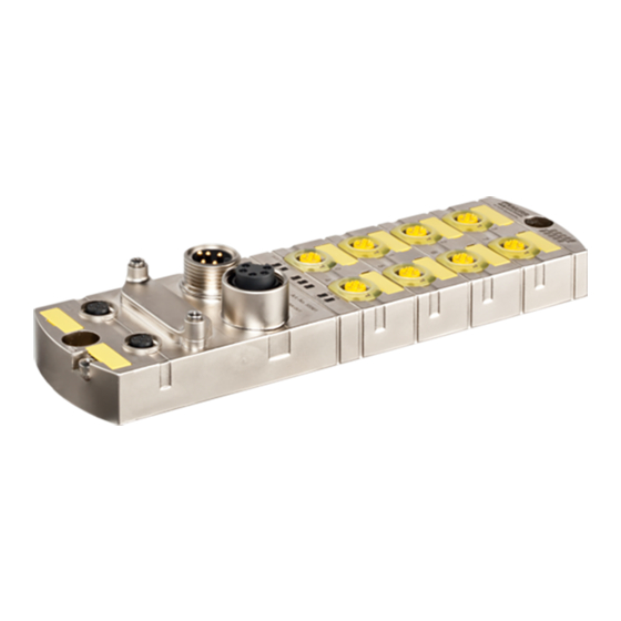
Describes the physical properties and robustness of the MVK-MPNIO module.
3.4.1 Module structure
Illustrates the physical layout and connection ports of the module.
3.4.2 Connections
Details the pin assignments for various connectors (DIO, IO-Link, POWER).
3.4.3 Display elements
Explains the function of the LEDs on the module for status indication.
3.4.4 DIP switch settings
Describes the function and configuration of the DIP switches.
4 Technical Data
4.1 Art.-No. 55530 MVK-MPNIO DIO16 IRT
Technical specifications for the DIO16 IRT module.
4.1.1 Electrical data
Details electrical parameters like voltage, current, and supply.
4.1.2 Environmental characteristics
Specifies operating conditions like temperature, humidity, and installation height.
4.1.3 Protection
Outlines device protection features against overvoltage and short circuits.
4.1.4 Mechanical data
Provides mechanical specifications like dimensions, weight, and housing material.
4.1.5 Product reliability
Information on product reliability, including MTTF data.
4.1.6 Conformity, Approvals
Lists product standards, certifications, and hazardous substance information.
4.2 Art.-No. 55531 MVK-MPNIO DIO14 IOL2 IRT
Technical specifications for the DIO14 IOL2 IRT module.
4.2.1 Electrical data
Details electrical parameters like voltage, current, and supply for this model.
4.2.2 Environmental characteristics
Specifies operating conditions for this model.
4.2.3 Protection
Outlines device protection features for this model.
4.2.4 Mechanical data
Provides mechanical specifications for this model.
4.2.5 Product reliability
Information on product reliability for this model.
4.2.6 Conformity, Approvals
Lists certifications and hazardous substance information for this model.
4.3 Art.-No. 55532 MVK-MPNIO DIO12 IOL4 IRT
Technical specifications for the DIO12 IOL4 IRT module.
4.3.1 Electrical data
Details electrical parameters for this model.
4.3.2 Environmental characteristics
Specifies operating conditions for this model.
4.3.3 Protection
Outlines device protection features for this model.
4.3.4 Mechanical data
Provides mechanical specifications for this model.
4.3.5 Product reliability
Information on product reliability for this model.
4.3.6 Conformity, Approvals
Lists certifications and hazardous substance information for this model.
5 Mounting
5.1 Requirements
Conditions and prerequisites for proper module mounting.
5.2 Dimensions
Provides physical dimensions and mounting diagram of the module.
5.3 Mounting distance
Specifies recommended spacing for heat dissipation and installation.
5.4 Installing the module
Instructions and notices for installing the module correctly.
5.4.1 Functional ground
Details how to establish a proper functional ground connection.
5.4.2 Addressing lid
Instructions for fastening the addressing lid.
6 Installation
6.1 Electrical Installation of the Module
General safety and installation guidelines for electrical connections.
6.1.1 Sensors and actuators
Instructions for connecting sensors and actuators via M12 ports.
6.1.2 Connecting the Ethernet bus
Guidance on connecting the Ethernet bus to the module.
6.1.3 Power supply connection
Instructions for connecting the module's power supply.
6.2 Ensuring Tightness (IP67)
Procedures to ensure IP67 protection by sealing unused connectors.
7 Start-up
7.1 Loading GSDML Files
Instructions for installing GSDML files required for device configuration.
8 Configuration/settings
8.1 Module configuration
Overview of configuring individual IO-Link ports and virtual modules.
8.1.1 Basic configuration
Shows basic module configuration in TIA Portal for different article numbers.
8.1.2 Basic configuration with submodules for diagnostic
Details configuring submodules for diagnostics in TIA Portal.
8.2 Module parameterization
Explains the various parameterization options for the module.
8.2.1 Module parameters
Lists and describes individual module parameters.
8.2.2 Diagnostic parameters
Details configuration of diagnostic reporting and undervoltage parameters.
8.2.3 Tool parameters
Configuration of the Murrelektronik IO-Link Device Tool access.
8.2.4 General parameters
Configuration of general parameters like IO layout and input delay.
8.2.5 Description of the parameters of the IO-Link ports
Detailed explanation of IO-Link port parameters.
8.3 IO-Link communication
How to configure and integrate IO-Link devices.
8.3.1 Cyclic and acyclic communication
Explains cyclic and acyclic data exchange in IO-Link.
8.3.1.1 Acyclic IO-Link access
Accessing data areas via PN-IO read/write services.
8.3.1.2 I&M data
Reading and writing Identification & Maintenance (I&M) data.
8.3.1.3 IO-Link device function block
Using the IO_LINK_DEVICE function block in TIA Portal.
8.4 Basic setting
Procedures for identifying and assigning names to modules.
8.4.1 Temporary IP address
How to assign a temporary IP address to the module.
8.5 Planning the PROFINET topology
Setting up the PROFINET topology and automatic recognition.
8.6 Project planning of the Fast Start Up
Configuring the module for Fast Start-Up (FSU) and prioritized startup.
8.7 Media redundancy (MRP) configuration
Steps for configuring Media Redundancy Protocol (MRP).
8.8 Isochronous real time (IRT) configuration
Procedure for configuring IRT operation with sync master/slave.
8.9 Shared Device configuration
Steps to configure the Shared Device functionality.
8.10 SNMP
How to send and receive SNMP messages for module monitoring.
8.11 PROFIenergy configuration
Configuration of PROFIenergy for energy saving modes.
8.12 Factory settings
Procedures for resetting the module to factory settings.
9 Operation
9.1 LED indications
Explains the meaning of various LED indicators on the module.
9.1.1 LED indication Digital inputs
Indicates status of digital inputs via LEDs.
9.1.2 LED indication Digital outputs
Indicates status of digital outputs via LEDs.
9.1.3 LED display IO-Link
Shows IO-Link status indication via LEDs.
9.1.4 LED indication ST
Indicates status and error conditions via the ST LED.
9.1.5 LED indication BUS RUN
Shows the state of the bus system via the BUS RUN LED.
9.1.6 LED indication CfgF
Indicates the PLC configuration status via the CfgF LED.
9.1.7 LED indication for LNK/ACT
Shows Ethernet communication status via LNK/ACT LEDs.
9.1.8 LED indication POWER US
Indicates supply voltages (US) via the POWER US LED.
9.1.9 LED indication POWER UA
Indicates supply voltages (UA) via the POWER UA LED.
9.2 Extended LED indications
Detailed LED indications for PROFIenergy, firmware updates, and factory reset.
9.3 PROFINET Diagnostics
Information on diagnostic alarms sent by the module.
9.3.1 General diagnostic messages
Lists general diagnostic messages, their meanings, and actions.
9.3.2 General diagnostic messages at IO-Link ports
Lists IO-Link port specific diagnostic messages.
9.3.3 Diagnostic messages at IO-Link ports
Detailed diagnostic messages for IO-Link ports according to guidelines.
9.3.3.1 According to IO-Link integration guideline Edition 1
Specific diagnostic messages based on the IO-Link integration guideline.
9.3.3.2 Murrelektronik IO-Link - Integration and extended integration
Diagnostics related to Murrelektronik specific IO-Link integration.
11 Appendix
11.1 Accessories
Lists available accessories and tools for the module.
11.1.1 Tools
Lists tools recommended for module installation and setup.
11.2 Glossary
Definitions of technical terms used in the manual.
Need help?
Do you have a question about the 55532 and is the answer not in the manual?
Questions and answers