Table of Contents
Advertisement
Quick Links
サーボパック
AC
Σ-II
シリーズ
取扱説明書
MECHATROLINK
形式:
JUSP-NS100
対象サーボパック形式:
SGDH-E-
製品を安全にお使い頂くために,本書を必ずお読みください。
また,本書をお手元に保管していただくとともに,最終的に本製品をご使用になる
ユーザー様のお手元に確実に届けられるよう,お取り計らい願います。
AC SERVOPACK
Σ
II
-
Series
INSTRUCTIONS
MECHATROLINK Interface Module
Model: JUSP-NS100
Applicable SERVOPACK Model: SGDH-E-
To properly use the product, read this manual thoroughly and retain
for easy reference, inspection, and maintenance. Ensure the end user
receives this manual.
MANUAL NO. TOB-C718-4C
インタフェースモジュール
Advertisement
Table of Contents

Related Manuals for YASKAWA JUSP-NS100


Summarization of Contents
Introduction
Manual Contents Overview
Details the manual's structure, comprising Japanese and English versions for user reference.
Target Audience Identification
Identifies intended users for checking, installation, operation, and maintenance of the Σ-II Series SERVOPACK.
Safety Symbols and Notes
Symbols for Safe Operation
Defines WARNING and CAUTION symbols used for safety instructions in the manual.
General Safe Operation Notes
General advice to read the manual thoroughly before installation, operation, or maintenance.
Checking on Delivery
Warning: SERVOPACK Version Compatibility
Do not use NS100 Module with SGDH SERVOPACK version 12 to prevent unintended brake release.
Caution: Software Version Limitations
Limitations in combining SGDH SERVOPACK and NS100 Module software versions to avoid errors.
Checking Items
Verify delivered products, motor shaft, and SERVOPACK type applicability.
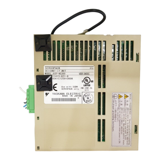
Appearance and Nameplate Inspection
Inspect the physical appearance and read the nameplate details of the module.
Type Designation
Information on the model and design revision order for the SERVOPACK peripheral device.
Mounting NS100 Module
Step-by-step guide on how to mount the NS100 Module onto a SGDH SERVOPACK.
Installation Guidelines
Caution: Environmental Hazards
Never use equipment exposed to water splashes, corrosive gases, or flammable materials.
Storage Guidelines
Guidelines for storing the SERVOPACK when the power cable is disconnected, specifying temperature range.
Installation Sites
Notes on selecting appropriate installation sites considering control panels, heat, vibration, and corrosive gases.
Orientation
Instructions for correctly orienting the SERVOPACK perpendicular to the wall for installation.
Installation Precautions
Precautions for side-by-side installation, spacing, cooling, and environmental conditions in control panels.
Wiring Procedures
Warning: Grounding Requirements
SERVOPACK grounding must follow national code and local practices for safety.
Caution: Power and Terminal Connections
Do not connect three-phase power to U, V, W terminals. Securely tighten screws to prevent fire.
MECHATROLINK Connection Example
Illustrates an example of connecting multiple SERVOPACKs via MECHATROLINK.
Wiring Precautions
Details on connectable stations, cables, total cable length, and terminators for MECHATROLINK wiring.
Operation Instructions
Caution: Test Run and Operation Safety
Run servomotor without load for test runs. Set parameters before operating with a load.
Precautions at Operation
Safety warning during operation: do not touch the SERVOPACK'S heatsink to avoid burns.
Inspection and Maintenance
Warning: Pre-Maintenance Safety
Turn OFF power, wait 5 minutes, and never open terminal cover when power is ON.
Caution: Wiring During Maintenance
Never change wiring while power is ON to prevent electric shock or injury.
General Precautions
Warning Label and Grounding
Key safety warnings including electric shock, burns, and proper grounding techniques.
Measures to Satisfy EMC Directive
MECHATROLINK Communication Cable
Use twisted pair shielded cable for serial communication (CN6A, CN6B) connectors. Max cable length is 50 m.
Fully Closed Encoder Cable
Use twisted pair shielded cable for the fully closed encoder (CN4) connector.
Cable Core Installation
Instructions on attaching a core (ESD-SR-25) to the MECHATROLINK and encoder cables.
Cable Clamp Method
Method for fixing and grounding the cable shield using a piece of conductive metal clamp.
Wiring Examples
Diagrams showing wiring examples, including noise filters and cores, for electrical experts.
Need help?
Do you have a question about the JUSP-NS100 and is the answer not in the manual?
Questions and answers