
Related Manuals for Dell EMC E17W


Summary of Contents for Dell EMC E17W
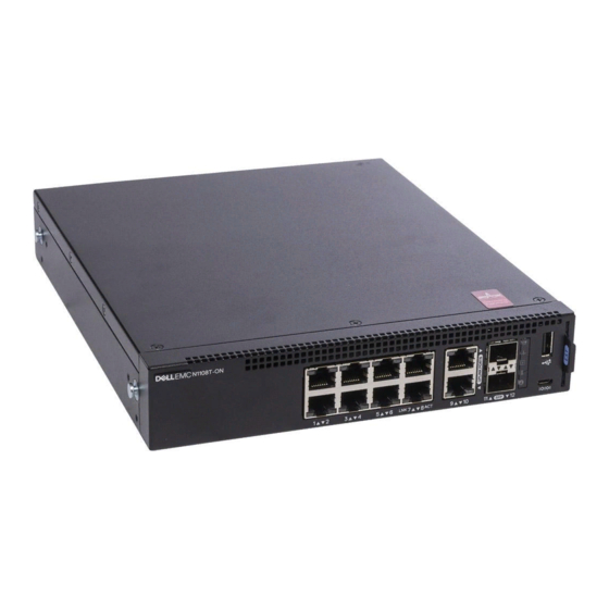
- Page 1 Dell Networking N1108T-ON/N1108P-ON/ N1108EP-ON/N1124T-ON/ N1124P-ON/N1148T-ON/ N1148P-ON Switches Getting Started Guide دﻟﻴﻞ ﺑﺪء اﻟﺘﺸﻐﻴﻞ Regulatory Model: E17W and E18W Regulatory Type: E17W001/E18W001/E18W002...
- Page 2 Dell Networking N1108T-ON/N1108P-ON/ N1108EP-ON/N1124T-ON/ N1124P-ON/N1148T-ON/ N1148P-ON Switches Getting Started Guide Regulatory Models: E17W and E18W...
- Page 3 Notes, Cautions, and Warnings NOTE: A NOTE indicates important information that helps you make better use of your switch. CAUTION: A CAUTION indicates either potential damage to hardware or loss of data and tells you how to avoid the problem. WARNING: A WARNING indicates a potential for property damage, personal injury, or death.
-
Page 4: Table Of Contents
Contents Introduction ......N1100-ON Series Hardware Overview ..Power Consumption for N1100-ON Series PoE Switches . - Page 5 Starting and Configuring the N1100-ON Series Switch ... . . Connecting an N1100-ON Series Switch to a Terminal ......Connecting an N1100-ON Series Switch to a Power Source .
-
Page 6: Introduction
Introduction This document provides basic information about the Dell Networking N1100-ON Series switches, including how to install a switch and perform the initial configuration. For information about how to configure and monitor switch features, refer to the User Configuration Guide, which is available on the Dell Support website at dell.com/support. -
Page 7: Ventilation System
Model Input Voltage Power Supply Maximum Steady Maximum Configuration Current Steady Consumption (A) Power (W) N1108EP-ON 100V/60Hz 54VDC External 1.62A 157W power adaptor 110V/60Hz 54VDC External 1.47A 157W power adaptor 120V/60Hz 54VDC External 1.35A 157W power adaptor 220V/50Hz 54VDC External 0.74A 157W power adaptor... -
Page 8: N1100-On Series Model Summary
N1100-ON Series Model Summary Table 1-2. N1100-ON Series Switch Regulatory Numbers Marketing Description Power Supply Regulatory Regulatory Model Name Unit (PSU) Model Number Type Number (MMN) (RMN) (RTN) N1108T-ON 10x1G/2x1G SFP Ports DPS-24GP E17W E17W001 N1108P-ON 10x1G/2x1G SFP/2xPoE+ Ports DPS-80AP/ E17W E17W001 DPS-24GP... -
Page 9: N1108T-On/N1108P-On/N1108Ep-On Installation
N1108T-ON/N1108P-ON/N1108EP- ON Installation Mounting an N1108T-ON/N1108P-ON Switch Using Dell Tandem Tray The AC power connector is on the rear panel. WARNING: Safety and Regulatory Information Read the safety information in the as well as the safety information for other switches that connect to or support the switch. -
Page 10: Mounting An N1108T-On/N1108P-On/N1108Ep-On On A Two-Post Rack Using Large L-Brackets
3 Secure the kit to the rack with either the rack bolts or cage nuts and cage- nut bolts with washers (depending on the kind of rack you have). Fasten the bolts on the bottom before fastening the bolts on the top. Mounting an N1108T-ON/N1108P-ON/N1108EP- ON on a Two-Post Rack Using Large L-brackets NOTE:... -
Page 11: Mounting All N11Xx-On Switches On A Wall
4 Insert the switch and rail assembly into the rack from the front of the rack. Make sure that the rack-mounting holes on the switch line up to the mounting holes on the rack. 5 Secure the switch to the rack with the rack screws. Fasten the lower pair of screws before the upper pair of screws. - Page 12 Figure 1-4. Inserting Mounting Brackets 4 Repeat the process for the wall-mounting bracket on the other side of the switch. 5 Place the switch on the wall in the location where the switch is being installed. 6 Mark the locations on the wall where the screws to hold the switch must be prepared.
- Page 13 Figure 1-5. Mounting on a Wall Getting Started Guide...
-
Page 14: N1124T-On/N1124P-On/N1148T-On/ N1148P-On Installation
N1124T-ON/N1124P-ON/N1148T-ON/ N1148P-ON Installation Rack Mounting an N1124T-ON/N1124P-ON/ N1148T-ON/ N1148P-ON Switch WARNING: Safety and Regulatory Information Read the safety information in the as well as the safety information for other switches that connect to or support the switch. The AC power connector is on the rear panel of the switch. Installing in a Rack WARNING: Do not use rack mounting kits to suspend the switch from under a... -
Page 15: Installing As A Free-Standing Switch
2 Insert the supplied bolts into the rack-mounting holes and tighten with a screwdriver. 3 Repeat the process for the rack-mounting bracket on the other side of the switch. 4 Insert the switch into the 48.26 cm (19 inch) rack, ensuring that the rack- mounting holes on the bracket line up with the mounting holes in the rack. -
Page 16: Starting And Configuring The N1100-On Series Switch
Starting and Configuring the N1100-ON Series Switch The following flow chart provides an overview of the steps you use to perform the initial configuration after the switch is unpacked and mounted. Installation and Configuration Flow Chart Figure 1-7. Getting Started Guide... -
Page 17: Connecting An N1100-On Series Switch To A Terminal
Connecting an N1100-ON Series Switch to a Terminal After completing all external connections, configure the switch by connecting it to a terminal. NOTE: Read the Release Notes for this product before proceeding. You can download the Release Notes from the Dell Support website at dell.com/support. NOTE: Dell recommends that you obtain the most recent version of the user documentation from the Dell Support website at dell.com/support. -
Page 18: Connecting An N1100-On Series Switch To A Power Source
NOTE: Console access to the stack manager is available from any console port via the local CLI. Only one USB console session at a time is supported. Connecting an N1100-ON Series Switch to a Power Source CAUTION: Safety and Regulatory Information Read the safety information in the manual as well as the safety information for other switches that connect to or support the switch. -
Page 19: Booting The N1100-On Series Switch
Booting the N1100-ON Series Switch When the power is turned on with the local terminal already connected, the switch goes through a power-on self-test (POST). POST runs every time the switch is initialized and checks hardware components to determine if the switch is fully operational before completely booting. -
Page 20: Performing The N1100-On Series Initial Configuration
Performing the N1100-ON Series Initial Configuration The initial configuration procedure is based on the following assumptions: • The Dell Networking switch was never configured before. • The Dell Networking switch booted successfully. • The console connection was established, and the Dell Easy Setup Wizard prompt appears on the screen of a PC running terminal emulation software. -
Page 21: Initial Configuration Procedure
Initial Configuration Procedure Perform the initial configuration by using the Dell Easy Setup Wizard or by using the CLI. The wizard automatically starts when the switch configuration file is empty. Exit the wizard at any point by entering [ctrl+z], but all configuration settings specified will be discarded, and the switch will use the default values. -
Page 22: Example Session
Example Session This section describes a Dell Easy Setup Wizard session. The following values are used by the example session: • The SNMP community string to be used is public. • The network management system (NMS) IP address is 10.1.2.100. •... -
Page 23: Dell Easy Setup Wizard Console Example
Dell Easy Setup Wizard Console Example The following example contains the sequence of prompts and responses associated with running an example Dell Easy Setup Wizard session, using the input values listed earlier. After the switch completes the POST and is booted, the following dialog appears: Unit 1 - Waiting to select management unit)>... - Page 24 receive related repair services from Dell. You further agree to allow Dell to transmit and store the Collected Data from SupportAssist in accordance with these terms. You agree that the provision of SupportAssist may involve international transfers of data from you to Dell and/or to Dell's affiliates, subcontractors or business partners.
- Page 25 with normal operation using the default system configuration. Note: You can exit the setup wizard at any point by entering [ctrl+z]. Would you like to run the setup wizard (you must answer this question within 60 seconds)? [Y/N] y Step 1: The system is not set up for SNMP management by default.
- Page 26 Step 2: Now we need to set up your initial privilege (Level 15) user account. This account is used to login to the CLI and Web interface. You may set up other accounts and change privilege levels later. For more information on setting up user accounts and changing privilege levels, see the user documentation.
-
Page 27: Next Steps
Finally, set up the default gateway. Please enter the IP address of the gateway from which this network is reachable. [0.0.0.0]: 10.1.1.1 This is the configuration information that has been collected: SNMP Interface = “public”@10.1.2.100 User Account setup = admin Password = ******** VLAN1 Router Interface IP = 10.1.1.200 255.255.255.0 Default Gateway = 10.1.1.1... - Page 28 The N1100-ON Series switches support basic switching features such as VLANs and spanning tree protocol. Use the Web-based management interface or the CLI to configure the features your network requires. For information about how to configure the switch features, refer to the User Configuration Guide or CLI Reference Guide available on the support site: dell.com/support.
-
Page 29: Agency Compliance
This product is in conformity with the protection requirements of EU Council Directive 2004/30/EC on the approximation of the laws of the Member States relating to electromagnetic compatibility. Dell EMC cannot accept responsibility for any failure to satisfy the protection requirements resulting from a non-recommended modification of this product, including the fitting of non-Dell EMC option cards. - Page 30 Safety standards and compliance agency certifications • IEC 62368-1, 2nd Edition • CUS UL 60950-1, 2nd Edition • Meets or exceeds Hi Pot and Ground Continuity testing per UL 60950-1. • AS/NZS 60950 • CSA 60950-1-03, 2nd Edition • EN 60950-1, 2nd Edition •...
- Page 31 Dell EMC encourages owners of information technology (IT) equipment to responsibly recycle their equipment when it is no longer needed. Dell EMC offers a variety of product return programs and services in several countries to assist equipment owners in recycling their IT products.
- Page 32 EEE on the environment and human health due to the potential presence of hazardous substances in EEE. Dell EMC products, which fall within the scope of the WEEE, are labeled with the crossed-out wheelie-bin symbol, as shown above, as required by WEEE.
- Page 33 Dell Networking N1108T-ON ت اﻟﻤﺤﻮﻻ N1108P-ON/N1108EP-ON N1124T-ON/N1124P-ON N1148T-ON/N1148P-ON دﻟﻴﻞ ﺑﺪء اﻟﺘﺸﻐﻴﻞ E18W و E17W :اﻟﻄﺮازات اﻟﺘﻨﻈﻴﻤﻴﺔ...
- Page 34 ﺣﻈﺎت واﻟﺘﻨﺒﻴﻬﺎت واﻟﺘﺤﺬﻳﺮات اﻟﻤﻼ :ﺣﻈﺔ ﻣﻼ ﺣﻈﺔ" إﻟﻰ ﻣﻌﻠﻮﻣﺎت ﻣﻬﻤﺔ ﺗﺴﺎﻋﺪك ﻋﻠﻰ ﺗﺤﻘﻴﻖ أﻗﺼﻰ اﺳﺘﻔﺎدة ﻣﻦ اﻟﻤﺤﻮل ﺗﺸﻴﺮ آﻠﻤﺔ "ﻣﻼ .ﺑﻚ اﻟﺨﺎص :ﺗﻨﺒﻴﻪ ﺟﻬﺰة أو ﻓﻘﺪان ﻟﻠﺒﻴﺎﻧﺎت، آﻤﺎ ﺗﻌﻠﻤﻚ ﺑﻜﻴﻔﻴﺔ ﺗﺠﻨﺐ ﺗﺸﻴﺮ آﻠﻤﺔ "ﺗﻨﺒﻴﻪ" إﻣﺎ إﻟﻰ اﺣﺘﻤﺎل ﺣﺪوث ﺗﻠﻒ ﺑﺎﻷ .اﻟﻤﺸﻜﻠﺔ...
- Page 35 اﻟﻤﺤﺘﻮﻳﺎت ﻘﺪﻣﺔ ُ ﻣ ......N1100-ON Series ﻧﻈﺮة ﻋﺎﻣﺔ ﻋﻠﻰ أﺟﻬﺰة ..PoE N1100-ON Series ت...
- Page 36 N1100-ON Series ﺗﺸﻐﻴﻞ وﺗﻬﻴﺌﺔ اﻟﻤﺤﻮل ﻓﻲ ﻣﺤﻄﺔ ﻃﺮﻓﻴﺔ N1100-ON Series ﺗﻮﺻﻴﻞ اﻟﻤﺤﻮل ..ﺗﻮﺻﻴﻞ ﻣﺤﻮل ﺑﻤﺼﺪر إﻣﺪاد ﺑﺎﻟﺘﻴﺎر N1100-ON Series . . . ﺗﻮﺻﻴﻞ ﻃﺎﻗﺔ اﻟﺘﻴﺎر اﻟﻤﺘﺮدد واﻟﺘﻴﺎر اﻟﻤﺴﺘﻤﺮ ..N1100-ON Series ﺗﻤﻬﻴﺪ...
- Page 37 ﻘﺪﻣﺔ ُ ﻣ ﺑﻤﺎ N1100-ON Series Dell Networking ت ﻳﻮﻓﺮ هﺬا اﻟﻤﺴﺘﻨﺪ ﻣﻌﻠﻮﻣﺎت أﺳﺎﺳﻴﺔ ﻋﻦ ﻣﺤﻮﻻ ﻓﻲ ذﻟﻚ آﻴﻔﻴﺔ ﺗﺮآﻴﺐ ﻣﺤﻮل وإﺟﺮاء اﻟﺘﻬﻴﺌﺔ اﻟﻤﺒﺪﺋﻴﺔ. ﻟﻠﺤﺼﻮل ﻋﻠﻰ ﻣﻌﻠﻮﻣﺎت ﻋﻦ آﻴﻔﻴﺔ ﺗﻬﻴﺌﺔ ﻣﻴﺰات ﻋﻠﻰ Dell اﻟﻤﺤﻮل وﻣﺮاﻗﺒﺘﻬﺎ، راﺟﻊ دﻟﻴﻞ ﺗﻬﻴﺌﺔ اﻟﻤﺴﺘﺨﺪم اﻟﻤﺘﺎح ﻋﻠﻰ ﻣﻮﻗﻊ اﻟﻮﻳﺐ اﻟﺨﺎص ﺑﺎﻟﺪﻋﻢ ﻣﻦ ﻟﻤﻌﺮﻓﺔ...
- Page 38 ﻗﺼﻰ اﻟﺤﺪ اﻷ ﻗﺼﻰ اﻟﺤﺪ اﻷ ﻣﺪاد ﺗﻬﻴﺌﺔ وﺣﺪة اﻹ دﺧﺎل ﻓﻮﻟﺘﻴﺔ اﻹ اﻟﻄﺮاز ﻟﻠﻘﺪرة اﻟﺜﺎﺑﺘﺔ ك اﻟﺘﻴﺎر ﺳﺘﻬﻼ ﻻ ﺑﺎﻟﺘﻴﺎر ()وات (اﻟﺜﺎﺑﺖ )أﻣﺒﻴﺮ وات أﻣﺒﻴﺮ 1.62 ﻣﻬﺎﻳﺊ ﺗﻴﺎر ﺧﺎرﺟﻲ هﺮﺗﺰ /ﻓﻮﻟﺖ N1108EP-ON ﻓﻮﻟﺖ ﻣﺴﺘﻤﺮ ﺑﻘﺪرة وات أﻣﺒﻴﺮ 1.47 ﻣﻬﺎﻳﺊ ﺗﻴﺎر ﺧﺎرﺟﻲ هﺮﺗﺰ...
- Page 39 ﻧﻈﺎم اﻟﺘﻬﻮﻳﺔ ﺑﻴﻨﻤﺎ ﺗﻘﻮم ﻣﺮوﺣﺘﺎن ﺑﺘﺒﺮﻳﺪ N1108T-ON/N1108P-ON ت ﺗﻘﻮم ﻣﺮوﺣﺔ واﺣﺪة ﺑﺘﺒﺮﻳﺪ ﻣﺤﻮﻻ . واﻟﻤﺮاوح ﻏﻴﺮ ﻗﺎﺑﻠﺔ N1024T-ON/N1024P-ON/N1048T-ON/N1048P ت ﻣﺤﻮﻻ .ﻣﺮوﺣﺔ ﺑﻼ ً ﻣﺤﻮ ﻻ N1108EP-ON ﻌﺪ ُ ﺳﺘﺒﺪال ﻓﻲ اﻟﻤﻮﻗﻊ. ﻳ ﻟﻼ N1100-ON Series ﻣﻠﺨﺺ اﻟﻄﺮاز N1100-ON Series رﻗﺎم اﻟﺘﻨﻈﻴﻤﻴﺔ ﻟﻠﻤﺤﻮل اﻷ...
- Page 40 N1108T-ON ﺗﺮآﻴﺐ اﻟﻤﺤﻮل N1108P-ON/N1108EP-ON ﺑﺎﺳﺘﺨﺪام N1108T-ON/N1108P-ON ﺗﺮآﻴﺐ اﻟﻤﺤﻮل Dell اﻟﺪرج اﻟﻤﺘﺮادف ﻣﻦ .ﻳﻮﺟﺪ ﻣﻮﺻﻞ ﻃﺎﻗﺔ اﻟﺘﻴﺎر اﻟﻤﺘﺮدد ﻓﻲ اﻟﻠﻮﺣﺔ اﻟﺨﻠﻔﻴﺔ :ﺗﺤﺬﻳﺮ ﻣﺔ ﺿﺎﻓﺔ إﻟﻰ ﻣﻌﻠﻮﻣﺎت اﻟﺴﻼ ﻣﺔ واﻟﻤﻌﻠﻮﻣﺎت اﻟﺘﻨﻈﻴﻤﻴﺔ ﺑﺎﻹ ﻣﺔ ﻓﻲ ﻣﻌﻠﻮﻣﺎت اﻟﺴﻼ اﻗﺮأ ﻣﻌﻠﻮﻣﺎت اﻟﺴﻼ .ﺧﺮى اﻟﺘﻲ ﺗﺘﺼﻞ ﺑﺎﻟﻤﺤﻮل أو ﺗﺪﻋﻤﻪ ت...
- Page 41 ﺛﺒﺖ اﻟﻤﺠﻤﻮﻋﺔ ﻓﻲ اﻟﺤﺎﻣﻞ ﺑﻮاﺳﻄﺔ ﻣﺴﺎﻣﻴﺮ اﻟﺤﺎﻣﻞ أو اﻟﺼﻮاﻣﻴﻞ اﻟﻤﺮﺑﻌﺔ واﻟﻤﺴﺎﻣﻴﺮ اﻟﻤﺰودة ﺳﻔﻞ ﻗﺒﻞ ﺑﺼﻮاﻣﻴﻞ ﻣﺮﺑﻌﺔ ﻣﻊ ﺟﻠﺒﺎت )ﺣﺴﺐ ﻧﻮع اﻟﺤﺎﻣﻞ اﻟﻤﺘﻮﻓﺮ ﻟﺪﻳﻚ(. ارﺑﻂ اﻟﻤﺴﺎﻣﻴﺮ اﻟﻤﻮﺟﻮدة ﺑﺎﻷ .ﻋﻠﻰ ﺗﺜﺒﻴﺖ اﻟﻤﺴﺎﻣﻴﺮ اﻟﻤﻮﺟﻮدة ﺑﺎﻷ N1108T-ON/N1108P-ON ﺗﺮآﻴﺐ اﻟﻤﺤﻮل ﻋﻠﻰ ﺣﺎﻣﻞ ﻣﺰود ﺑﺎﻟﺪﻋﺎﻣﺘﻴﻦ ﺑﺎﺳﺘﺨﺪام N1108EP-ON آﺒﻴﺮة...
- Page 42 ﻣﺎﻣﻲ ﻟﻠﺤﺎﻣﻞ. ﺗﺄآﺪ ﻣﻦ ﻣﺤﺎذاة ﻓﺘﺤﺎت أدﺧﻞ اﻟﻤﺤﻮل وﻣﺠﻤﻮﻋﺔ اﻟﻘﻀﻴﺐ ﻓﻲ اﻟﺤﺎﻣﻞ ﻣﻦ اﻟﺠﺰء اﻷ .اﻟﺘﺮآﻴﺐ ﻋﻠﻰ اﻟﺤﺎﻣﻞ ﻣﻊ ﻓﺘﺤﺎت اﻟﺘﺮآﻴﺐ اﻟﻤﻮﺟﻮدة ﻓﻲ اﻟﺤﺎﻣﻞ ﻗﻢ ﺑﺘﺜﺒﻴﺖ اﻟﻤﺤﻮل ﻓﻲ اﻟﺤﺎﻣﻞ ﺑﺎﺳﺘﺨﺪام اﻟﻤﺴﺎﻣﻴﺮ اﻟﻠﻮﻟﺒﻴﺔ اﻟﺨﺎﺻﺔ ﺑﺎﻟﺤﺎﻣﻞ. ارﺑﻂ زوج اﻟﻤﺴﺎﻣﻴﺮ اﻟﺸﻜﻞ اﻟﺴﻔﻠﻲ ﻗﺒﻞ اﻟﺰوج اﻟﻌﻠﻮي ﻟﻠﻤﺴﺎﻣﻴﺮ. راﺟﻊ اﻟﺘﺮآﻴﺐ...
- Page 43 إدﺧﺎل ﺣﻮاﻣﻞ اﻟﺘﺮآﻴﺐ اﻟﺸﻜﻞ .ﺧﺮ ﻟﻤﻔﺘﺎح اﻟﺘﺒﺪﻳﻞ آﺮر اﻟﻌﻤﻠﻴﺔ ﻟﺤﺎﻣﻞ اﻟﺘﺮآﻴﺐ ﻋﻠﻰ اﻟﺤﺎﺋﻂ ﻋﻠﻰ اﻟﺠﺎﻧﺐ اﻵ .ﺿﻊ ﻣﻔﺘﺎح اﻟﺘﺒﺪﻳﻞ ﻋﻠﻰ اﻟﺤﺎﺋﻂ ﻓﻲ اﻟﻤﻮﻗﻊ ﺣﻴﺚ ﻳﺘﻢ ﺗﺮآﻴﺐ ﻣﻔﺘﺎح اﻟﺘﺒﺪﻳﻞ .زﻣﺔ ﻟﺘﻌﻠﻴﻖ اﻟﻤﺤﻮل ﻗﻢ ﺑﺘﻤﻴﻴﺰ اﻟﻤﻮاﻗﻊ ﻋﻠﻰ اﻟﺤﺎﺋﻂ ﺣﻴﺚ ﻳﻠﺰم إﻋﺪاد اﻟﻤﺴﺎﻣﻴﺮ اﻟﻼ .رﺳﺎء...
- Page 44 اﻟﺘﺮآﻴﺐ ﻋﻠﻲ اﻟﺤﺎﺋﻂ اﻟﺸﻜﻞ دﻟﻴﻞ ﺑﺪء اﻟﺘﺸﻐﻴﻞ...
- Page 45 N1124T-ON/N1124P-ON ﺗﺮآﻴﺐ N1148T-ON/N1148P-ON N1124T-ON/N1124P-ON ﺗﺮآﻴﺐ ﻣﺤﻮل ﻋﻠﻰ اﻟﺤﺎﻣﻞ N1148T-ON/N1148P-ON :ﺗﺤﺬﻳﺮ ﺿﺎﻓﺔ إﻟﻰ ﻣﻌﻠﻮﻣﺎت ﻣﺔ واﻟﻤﻌﻠﻮﻣﺎت اﻟﺘﻨﻈﻴﻤﻴﺔ ﺑﺎﻹ ﻣﺔ ﻓﻲ ﻣﻌﻠﻮﻣﺎت اﻟﺴﻼ اﻗﺮأ ﻣﻌﻠﻮﻣﺎت اﻟﺴﻼ .ﺧﺮى اﻟﺘﻲ ﺗﺘﺼﻞ ﺑﺎﻟﻤﺤﻮل أو ﺗﺪﻋﻤﻪ ت اﻷ ﻣﺔ اﻟﺨﺎﺻﺔ ﺑﺎﻟﻤﺤﻮﻻ اﻟﺴﻼ .ﻳﻮﺟﺪ ﻣﻮﺻﻞ ﻃﺎﻗﺔ اﻟﺘﻴﺎر اﻟﻤﺘﺮدد ﻋﻠﻰ اﻟﻠﻮﺣﺔ اﻟﺨﻠﻔﻴﺔ ﻟﻠﻤﺤﻮل اﻟﺘﺮآﻴﺐ...
- Page 46 .أدﺧﻞ اﻟﻤﺴﺎﻣﻴﺮ اﻟﻤﺰودة داﺧﻞ ﻓﺘﺤﺎت اﻟﺘﺮآﻴﺐ ﻋﻠﻰ اﻟﺤﺎﻣﻞ وارﺑﻄﻬﺎ ﺑﺈﺣﻜﺎم ﺑﻮاﺳﻄﺔ ﻣﻔﻚ .ﺧﺮ ﻣﻦ اﻟﻤﺤﻮل آﺮر اﻟﻌﻤﻠﻴﺔ ﺑﺎﻟﻨﺴﺒﺔ ﻟﺪﻋﺎﻣﺔ اﻟﺘﺮآﻴﺐ ﻋﻠﻰ اﻟﺤﺎﻣﻞ ﻋﻠﻰ اﻟﺠﺎﻧﺐ اﻵ ﺑﻮﺻﺔ(، ﻣﻊ اﻟﺘﺄآﺪ ﻣﻦ ﻣﺤﺎذاة ﻓﺘﺤﺎت اﻟﺘﺮآﻴﺐ ﻋﻠﻰ ) ﺳﻢ 48.26 أدﺧﻞ اﻟﻤﺤﻮل داﺧﻞ ﺣﺎﻣﻞ .اﻟﺤﺎﻣﻞ...
- Page 47 N1100-ON Series ﺗﺸﻐﻴﻞ وﺗﻬﻴﺌﺔ اﻟﻤﺤﻮل ﺟﺮاء اﻟﺘﻬﻴﺌﺔ اﻟﻤﺒﺪﺋﻴﺔ ﺑﻌﺪ ﻓﻚ ﻳﻮﻓﺮ ﻣﺨﻄﻂ اﻟﺘﺪﻓﻖ اﻟﺘﺎﻟﻲ ﻧﻈﺮة ﻋﺎﻣﺔ ﻋﻠﻰ اﻟﺨﻄﻮات اﻟﺘﻲ ﺗﺴﺘﺨﺪﻣﻬﺎ ﻹ .ﺗﻐﻠﻴﻒ اﻟﻤﺤﻮل وﺗﺮآﻴﺒﻪ ﻣﺨﻄﻂ ﺗﺪﻓﻖ اﻟﺘﺮآﻴﺐ واﻟﺘﻬﻴﺌﺔ اﻟﺸﻜﻞ دﻟﻴﻞ ﺑﺪء اﻟﺘﺸﻐﻴﻞ...
- Page 48 ﻓﻲ ﻣﺤﻄﺔ ﻃﺮﻓﻴﺔ N1100-ON Series ﺗﻮﺻﻴﻞ اﻟﻤﺤﻮل .ل ﺗﻮﺻﻴﻠﻪ ﺑﻤﺤﻄﺔ ﻃﺮﻓﻴﺔ ت اﻟﺨﺎرﺟﻴﺔ، ﻗﻢ ﺑﺘﻬﻴﺌﺔ اﻟﻤﺤﻮل ﻣﻦ ﺧﻼ ﻧﺘﻬﺎء ﻣﻦ آﻞ اﻟﺘﻮﺻﻴﻼ ﺑﻌﺪ اﻻ :ﺣﻈﺔ ﻣﻼ ﺻﺪار ﻣﻦ ﻣﻮﻗﻊ ﺣﻈﺎت اﻹ ﺻﺪار ﻟﻬﺬا اﻟﻤﻨﺘﺞ ﻗﺒﻞ اﻟﻤﺘﺎﺑﻌﺔ. ﻳﻤﻜﻨﻚ ﺗﻨﺰﻳﻞ ﻣﻼ ﺣﻈﺎت اﻹ اﻗﺮأ...
- Page 49 ﺗﻮﺻﻴﻞ ﻣﺤﻮل ﺑﻤﺼﺪر إﻣﺪاد ﺑﺎﻟﺘﻴﺎر N1100-ON Series :ﺗﻨﺒﻴﻪ ﺿﺎﻓﺔ إﻟﻰ ﻣﻌﻠﻮﻣﺎت ﻣﺔ واﻟﻤﻌﻠﻮﻣﺎت اﻟﺘﻨﻈﻴﻤﻴﺔ ﺑﺎﻹ ﻣﺔ ﻓﻲ دﻟﻴﻞ ﻣﻌﻠﻮﻣﺎت اﻟﺴﻼ اﻗﺮأ ﻣﻌﻠﻮﻣﺎت اﻟﺴﻼ .ﺧﺮى اﻟﺘﻲ ﺗﺘﺼﻞ ﺑﺎﻟﻤﺤﻮل أو ﺗﺪﻋﻤﻪ ت اﻷ ﻣﺔ اﻟﺨﺎﺻﺔ ﺑﺎﻟﻤﺤﻮﻻ اﻟﺴﻼ ﻋﻠﻰ وﺣﺪة إﻣﺪاد ﺑﺎﻟﻄﺎﻗﺔ واﺣﺪة داﺧﻠﻴﺔ. ﻳﻮﺟﺪ N1108P-ON و...
- Page 50 N1100-ON Series ﺗﻤﻬﻴﺪ اﻟﻤﺤﻮل ﺧﺘﺒﺎر اﻟﺬاﺗﻲ ﻋﻨﺪ ﺗﺸﻐﻴﻞ اﻟﺘﻴﺎر ﻋﻨﺪﻣﺎ ﺗﻜﻮن اﻟﻤﺤﻄﺔ اﻟﻄﺮﻓﻴﺔ اﻟﻤﺤﻠﻴﺔ ﻣﺘﺼﻠﺔ ﺑﺎﻟﻔﻌﻞ، ﻳﺨﻀﻊ اﻟﻤﺤﻮل ﻟﻼ ( ﻓﻲ آﻞ ﻣﺮة ﻳﺘﻢ ﺗﻤﻬﻴﺪ POST ) ﺧﺘﺒﺎر اﻟﺬاﺗﻲ ﻋﻨﺪ ﺑﺪء اﻟﺘﺸﻐﻴﻞ (. وﻳﺒﺪأ اﻻ POST ) ﻋﻨﺪ ﺑﺪء اﻟﺘﺸﻐﻴﻞ .ﺑﺎﻟﻜﺎﻣﻞ...
- Page 51 اﻟﻤﺒﺪﺋﻴﺔ N1100-ON Series إﺟﺮاء ﺗﻬﻴﺌﺔ اﻟﻤﺤﻮل :ﻓﺘﺮاﺿﺎت اﻟﺘﺎﻟﻴﺔ ﻳﻌﺘﻤﺪ إﺟﺮاء اﻟﺘﻬﻴﺌﺔ اﻟﻤﺒﺪﺋﻴﺔ ﻋﻠﻰ اﻻ .ا ﻣﻦ ﻗﺒﻞ ً أﺑ ﺪ Dell Networking ﻟﻢ ﺗﺘﻢ ﺗﻬﻴﺌﺔ اﻟﻤﺤﻮل • .ﺑﻨﺠﺎح Dell Networking ﺗﻢ ﺗﻤﻬﻴﺪ اﻟﻤﺤﻮل • ﻋﻠﻰ ﺷﺎﺷﺔ ﺟﻬﺎز Dell Easy Setup Wizard ﺗﻢ...
- Page 52 إﺟﺮاء اﻟﺘﻬﻴﺌﺔ اﻟﻤﺒﺪﺋﻴﺔ أو ﺑﺎﺳﺘﺨﺪام واﺟﻬﺔ ﺳﻄﺮ Dell Easy Setup Wizard ﻗﻢ ﺑﺈﺟﺮاء اﻟﺘﻬﻴﺌﺔ اﻟﻤﺒﺪﺋﻴﺔ ﺑﺎﺳﺘﺨﺪام ﺎ. ﻗﻢ ﺑﺎﻟﺨﺮوج ﻣﻦ ً ﺎ ﻋﻨﺪﻣﺎ ﻳﻜﻮن ﻣﻠﻒ ﺗﻬﻴﺌﺔ اﻟﻤﺤﻮل ﻓﺎر ﻏ ً (. ﻳﺒﺪأ ﺗﺸﻐﻴﻞ اﻟﻤﻌﺎﻟﺞ ﺗﻠﻘﺎﺋ ﻴ ) واﻣﺮ اﻷ [، وﻟﻜﻦ ﺳﻴﺘﻢ اﻟﺘﺨﻠﺺ ﻣﻦ آﻞ إﻋﺪادات اﻟﺘﻬﻴﺌﺔ اﻟﻤﺤﺪدة ctrl+z ] ل...
- Page 53 ﻣﺜﺎل ﻟﺠﻠﺴﺔ :ﺴﺘﺨﺪم اﻟﻘﻴﻢ اﻟﺘﺎﻟﻴﺔ ﻣﻦ ﻗﺒﻞ ﻣﺜﺎل اﻟﺠﻠﺴﺔ ُ . ﺗ Dell Easy Setup Wizard هﺬا اﻟﻘﺴﻢ ﻳﺼﻒ ﺟﻠﺴﺔ ﻋﺎﻣﺔ اﻟﻤﺴﺘﺨﺪﻣﺔ SNMP ﺳﻠﺴﻠﺔ ﻣﺠﻤﻮﻋﺔ • 10.1.2.100 ( هﻮ ) ﻟﻨﻈﺎم إدارة اﻟﺸﺒﻜﺔ ﻋﻨﻮان • admin123 ، وآﻠﻤﺔ اﻟﻤﺮور هﻲ admin اﺳﻢ...
- Page 54 Dell Easy Setup Wizard ﻣﺜﺎل وﺣﺪة ﺗﺤﻜﻢ Dell Easy ﺳﺘﺠﺎﺑﺎت اﻟﻤﻘﺘﺮﻧﺔ ﺑﺘﺸﻐﻴﻞ ﻣﺜﺎل ﻟﺠﻠﺴﺔ ﻳﺤﺘﻮي اﻟﻤﺜﺎل اﻟﺘﺎﻟﻲ ﻋﻠﻰ ﺗﺴﻠﺴﻞ اﻟﻤﻄﺎﻟﺒﺎت واﻻ .ﺎ ً ﺪرﺟﺔ ﺳﺎﺑ ﻘ ُ دﺧﺎل اﻟ ﻤ ، ﺑﺎﺳﺘﺨﺪام ﻗﻴﻢ اﻹ Setup Wizard :( وﺗﻤﻬﻴﺪﻩ، ﻳﻈﻬﺮ اﻟﺤﻮار اﻟﺘﺎﻟﻲ POST ) ﺧﺘﺒﺎر...
- Page 55 receive related repair services from Dell. You further agree to allow Dell to transmit and store the Collected Data from SupportAssist in accordance with these terms. You agree that the provision of SupportAssist may involve international transfers of data from you to Dell and/or to Dell's affiliates subcontractors or business partners.
- Page 56 with normal operation using the default system configuration. Note: You can exit the setup wizard at any point by entering [ctrl+z Would you like to run the setup wizard (you must answer this question within 60 seconds)? [Y/N] y Step 1 The system is not set up for SNMP management by default.
- Page 57 Step 2 Now we need to set up your initial privilege (Level user account. This account is used to login to the CLI and Web interface. You may set up other accounts and change privilege levels later. For more information on setting up user accounts and changing privilege levels, see the user documentation To set up a user account Please enter the user name.
- Page 58 Finally, set up the default gateway. Please enter the IP address of the gateway from which this network is reachable. [0.0.0.0]: 10.1.1.1 This is the configuration information that has been collected SNMP Interface = “public”@10.1.2.100 User Account setup = admin ******** = Password VLAN1 Router Interface IP = 10.1.1.200 255.255.255.0...
- Page 59 وﺑﺮوﺗﻮآﻮل VLAN ﺳﺎﺳﻴﺔ ﻣﺜﻞ ﺷﺒﻜﺎت ﻣﻴﺰات اﻟﺘﺤﻮﻳﻞ اﻷ N1100-ON Series ت ﺪﻋﻢ اﻟﻤﺤﻮﻻ ُ ﺗ ( ﻟﺘﻬﻴﺌﺔ اﻟﻤﻴﺰات ) واﻣﺮ اﻟﺘﻤﺪﻳﺪ اﻟﺸﺠﺮي. اﺳﺘﺨﺪم واﺟﻬﺔ إدارة ﻣﺴﺘﻨﺪة ﻋﻠﻰ اﻟﻮﻳﺐ أو واﺟﻬﺔ ﺳﻄﺮ اﻷ اﻟﻤﺴﺘﺨﺪم ﺗﻬﻴﺌﺔ اﻟﺘﻲ ﺗﺘﻄﻠﺒﻬﺎ ﺷﺒﻜﺘﻚ. ﻟﻠﺤﺼﻮل ﻋﻠﻰ ﻣﻌﻠﻮﻣﺎت ﻋﻦ آﻴﻔﻴﺔ ﺗﻬﻴﺌﺔ ﻣﻴﺰات اﻟﻤﺤﻮل، راﺟﻊ دﻟﻴﻞ dell.com/support :اﻟﻤﺮﺟﻌﻲ...
- Page 60 وروﺑﻲ ﺑﺘﻘﺪﻳﺮ ﺗﻘﺮﻳﺒﻲ ﻟﻘﻮاﻧﻴﻦ اﻟﺪول اﻷ ﺗﺤﺎد اﻷ اﻻ ﻗﺒﻮل أﻳﺔ ﻣﺴﺆوﻟﻴﺔ ﻋﻦ ﻋﺪم اﻟﻮﻓﺎء ﺑﻤﺘﻄﻠﺒﺎت اﻟﺤﻤﺎﻳﺔ اﻟﻨﺎﺗﺠﺔ ﻋﻦ ﺗﻌﺪﻳﻞ ﻏﻴﺮ ﻣﻮﺻﻰ Dell EMC ﻟﺸﺮآﺔ Dell EMC ﺑﻪ ﻓﻲ هﺬا اﻟﻤﻨﺘﺞ، ﺑﻤﺎ ﻓﻲ ذﻟﻚ ﺗﺮآﻴﺐ ﺑﻄﺎﻗﺎت اﺧﺘﻴﺎرﻳﺔ ﻟﻴﺴﺖ ﻣﻦ إﻧﺘﺎج...
- Page 61 ﻣﺘﺜﺎل ﻣﺔ وﺷﻬﺎدات وآﺎﻟﺔ اﻻ ﻣﻌﺎﻳﻴﺮ اﻟﺴﻼ ﺻﺪار اﻟﺜﺎﻧﻲ ، اﻹ IEC 62368-1 • ﺻﺪار اﻟﺜﺎﻧﻲ ، اﻹ CUS UL 60950-1 • .أو ﻳﺘﺠﺎوزهﺎ UL 60950-1 ﺄ ﻟﺸﻬﺎدة ً داء اﻟﻔﺎﺋﻖ واﺳﺘﻤﺮارﻳﺔ اﻟﺘﺄرﻳﺾ وﻓ ﻘ ﻳﻔﻲ ﺑﺎﺧﺘﺒﺎرات اﻷ • AS/NZS 60950 •...
- Page 62 ً ﻳﺠﺐ ﻋﻠﻴﻚ إﻋﺎدة ﺗﺪوﻳﺮ هﺬا اﻟﻨﻈﺎم أو اﻟﺘﺨﻠﺺ ﻣﻨﻪ وﻓ ﻘ ( ﻋﻠﻰ ﺗﺤﻤﻞ ﻣﺴﺆوﻟﻴﺔ إﻋﺎدة ﺗﺪوﻳﺮ أﺟﻬﺰﺗﻬﻢ ﻋﻨﺪ ) ﻣﺎﻟﻜﻲ أﺟﻬﺰة ﺗﻘﻨﻴﺔ اﻟﻤﻌﻠﻮﻣﺎت Dell EMC ﻣﺠﻤﻮﻋﺔ ﻣﺘﻨﻮﻋﺔ ﻣﻦ ﺑﺮاﻣﺞ وﺧﺪﻣﺎت إرﺟﺎع اﻟﻤﻨﺘﺠﺎت ﻓﻲ اﻟﻌﺪﻳﺪ ﻣﻦ Dell EMC ﺳﺘﻐﻨﺎء ﻋﻨﻬﺎ. ﺗﻘﺪم...
- Page 63 w w w .d el l .c om | d el l .c om / s up p or t...
Need help?
Do you have a question about the E17W and is the answer not in the manual?
Questions and answers