Table of Contents
Advertisement
Quick Links
Advertisement
Table of Contents

Related Manuals for ACTi Q113


Summarization of Contents
Introduction
The List of Models
Lists the available camera models: Q113 and Q115 included in this manual.
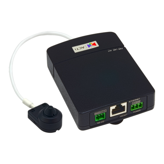
Physical Description
LED Indicators
Details the status indications for Power (PWR) and Link (LINK) LEDs.
Memory Card Slot
Description of the slot for microSDHC/microSDXC cards used for local recording.
Digital Input / Output
Explains the connection of digital input/output devices for event triggers or notifications.
Camera Port
Identifies the port used for connecting the camera itself to the main unit.
Audio Input / Output
Details the connection for audio devices like microphones and speakers.
Ethernet Port
Specifies the port for network connectivity using an Ethernet cable.
Serial Port
Describes the RS-232 serial port for connecting serial devices.
DC 12V Power Input
Connector for connecting an external DC 12V power adapter for non-PoE setups.
Reset Button
Location and function of the reset button to restore factory default settings.
Mounting Solutions
Surface Mount
For flat surface mounting (ceilings/walls) using the bundled surface mount.
Flush Mount
For installing the camera behind a surface, showing only the lens externally.
Tilted Wall Mount
For wall mounting on high locations, providing a 20° tilt for wider downward view.
Height Strip Mount
For discreet installation in height strip meters, e.g., near exit doors.
Installing the Main Unit
Mounting on DIN Rail
Step-by-step guide to mounting the main unit onto a standard DIN rail.
Using the Bundled Mounting Rail
Instructions for installing the main unit using the provided mounting rail accessory.
Installing the Camera with the Surface Mount
Step 1: Mount the Camera
Procedure for attaching the camera to a surface using the provided mount and screws.
Step 2: Route and Connect the Camera Cable
Guide for routing the camera cable and connecting it to the main unit.
Step 3: Connect to the Network
Instructions for connecting the main unit to the network via an Ethernet cable.
Step 4: Access the Camera Live View
Steps to access the camera's live video feed through a web browser.
Installing the Camera Using the Flush Mount
Step 1: Install the Flush Mount
Procedure to attach the flush mount to the installation surface using a drill template.
Step 2: Mount the Camera
Procedure for inserting the camera into the flush mount and securing its depth.
Step 3: Route and Connect the Camera Cable
Guide for routing the camera cable and connecting it to the main unit.
Step 4: Connect to the Network
Instructions for connecting the main unit to the network via an Ethernet cable.
Step 5: Access the Camera Live View
Steps to access the camera's live video feed through a web browser.
Installing the Camera Using the Tilted Mount
Step 1: Install the Tilted Mount
Procedure to attach the tilted mount to the wall using a drill template and screws.
Step 2: Mount the Camera
Procedure for mounting the camera to the tilted mount and attaching the surface mount.
Step 3: Route and Connect the Camera Cable
Guide for routing the camera cable and connecting it to the main unit.
Step 4: Connect to the Network
Instructions for connecting the main unit to the network via an Ethernet cable.
Step 5: Access the Camera Live View
Steps to access the camera's live video feed through a web browser.
Cable Connections
Connecting a Power Adapter (Optional)
Guide for connecting an external power adapter to the camera's terminal block.
Connecting DI/DO Devices (Optional)
Instructions for connecting digital input/output devices to the main unit's terminal block.
Connecting Audio In / Out Devices (Optional)
Guide for connecting audio input/output devices to the main unit's terminal block.
Connecting Serial Devices (Optional)
Procedure for connecting serial devices to the main unit's RS-232 terminal block.
Other Accessories
How to Install / Remove the Memory Card
Instructions for managing memory cards for local video recording.
How to Shorten the Camera Cable
Procedure for shortening the camera cable using RJ-12 connectors.
Accessing the Camera
Configure the IP Addresses
Methods for configuring IP addresses for camera communication with PCs.
Default IP Address Configuration
Information on the camera's default IP address and network setup requirements.
Manually Adjust PC IP Address
Step-by-step guide to manually set PC IP address for network segment matching.
Assign Multiple Camera IP Addresses
Using IP Utility to assign unique IP addresses to multiple cameras simultaneously.
Browser Access and Functionality
Guidance on accessing the camera via web browser and browser functionality comparison.
Web Browser Login Procedure
Instructions on accessing the camera via browser, including default login credentials.
Need help?
Do you have a question about the Q113 and is the answer not in the manual?
Questions and answers