Table of Contents
Advertisement
Quick Links
Advertisement
Table of Contents

Subscribe to Our Youtube Channel
Related Manuals for ACTi Q13


Summary of Contents for ACTi Q13
- Page 1 Covert Series Camera Hardware Manual Q13, Q111 2016/04/11...
-
Page 2: Table Of Contents
Connecting DI/DO Devices (Optional) ........... 21 Connecting Audio In / Out Devices (Optional) ......24 Connecting Serial Devices (Optional) ........... 25 Other Accessories How to Install / Remove the Memory Card ........26 How to Insert the Memory Card ........... 26 www.acti.com... - Page 3 Hardware Manual How to Remove the Memory Card ..........27 How to Shorten the Camera Cable ..........28 Accessing the Camera Configure the IP Addresses ............31 Access the Camera ................. 35 www.acti.com...
-
Page 4: Precautions
Every reasonable care has been taken during the writing of this manual. Please inform your local office if you find any inaccuracies or omissions. ACTi will not be held responsible for any typographical or technical errors and reserves the right to make changes to the product and manuals without prior notice. - Page 5 This product has been tested and found to comply with the limits for Class B Information Technology Equipment according to European Standard EN 55022 and EN 55024. In a domestic environment, this product may cause radio interference in which cause the user may be required to take adequate measures. www.acti.com...
-
Page 6: Safety Instructions
Safety Check Upon completion of any service or repairs to this product, ask the service technician to perform safety checks to determine if the product is in proper operating condition. www.acti.com... -
Page 7: Introduction
Hardware Manual Introduction The List of Models This hardware manual contains the following models: 2MP Indoor Fisheye Covert with Basic WDR, SLLS, Fixed lens Q111 5MP Indoor Fisheye Covert with Basic WDR, Fixed lens www.acti.com... -
Page 8: Package Contents
Terminal Block Terminal Block Terminal Block (for Power) (for DI/DO) (for Audio In/Out) Terminal Block Quick Installation Guide Warranty Card (for RS-232) Mounting Accessories Flush Mount & Flush Mount Camera Set Screw Mounting Rail Screws Drill Template Drill Template www.acti.com... -
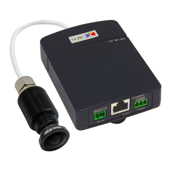
Page 9: Physical Description
DC 12V Power Input In case the camera is connected to a non-PoE (Power over Ethernet) switch, use this connector to connect the camera to an external power adapter. See Connecting a Power Adapter (Optional) on page 19 for more information. www.acti.com... - Page 10 Item Description Reset Button Restores the factory default settings of the camera. To reset the camera, while the power is on, press and hold the Reset Button for at least 5 seconds or until the Power LED goes off. www.acti.com...
-
Page 11: Mounting Solutions
ATM machine. The bracket is available for purchase. Installation procedures are covered in the Installation Guide downloadable from the website (http://www.acti.com/mountingselector). NOTE: For more information about the mounting solutions and accessories, please check the Mounting Accessory Selector in our website (http://www.acti.com/mountingselector). www.acti.com... -
Page 12: Installing The Main Unit
1. Install the mounting rail on the surface using the two (2) screws. 2. Attach the lower end of the main unit to the mounting rail. 3. Slightly push up the main unit and snap the upper end into place. www.acti.com... -
Page 13: Installing The Camera Using The Flush Mount
1. Attach the bundled Flush Mount drill template sticker on the target installation surface. 2. Mark the screw holes and the perimerter where to mount the flush mount. 3. Drill the lens hole. 4. After drilling the lens hole, remove the drill template. www.acti.com... -
Page 14: Step 2: Attach The Camera
(either upward or downward). The flat area indicates the correct viewing orientation of the camera. Then, attach the set screw to one of the screw holes on the flush mount to fix the camera position. www.acti.com... - Page 15 6. The adhesive on the flush mount is sufficient to hold the mount against most types of surfaces. Nevertheless, three (3) screws are bundled with the camera package that can be used to secure the flush mount. Use the screws as needed. www.acti.com...
- Page 16 Meanwhile, the installation on the other side of the surface will only show the camera lens. Example image below: 7. Peel off sticker from the flush mount top cover and attach the top cover to the camera with the adhesive side facing the surface to complete the installation. Final installation example below: www.acti.com...
-
Page 17: Step 3: Route And Connect The Camera Cable
3. Connect the camera cable connector to the Camera port of the main unit. Step 4: Connect to the Network 1. Connect one end of a network cable to the Ethernet port of the main unit. www.acti.com... -
Page 18: Step 5: Access The Camera Live View
3. As needed, connect and power up other devices, such as digital input/output, audio, or serial device. See Cable Connections on page 19 for more information on connecting other devices. Step 5: Access the Camera Live View Accessing the Camera on page 31 for more information. www.acti.com... -
Page 19: Cable Connections
1. Loosen the screws of the 12V and GND pins of the power terminal block. 2. Take note that a standard power adapter cable has two (2) different wires: Connects to GND Pin White stripe: Connects to 12V Pin www.acti.com... - Page 20 4. Tighten the screws of the 12V pin and the GND pins to secure the wire connection. 5. Set the prepared power adapter for connection later. Below is an example of a power adapter with an attached terminal block. NOTE: The power adapter is not bundled in the package. www.acti.com...
-
Page 21: Connecting Di/Do Devices (Optional)
Connect the wires of the digital input device to GND and Digital Input (DI) To connect an output device (DO), map the pins as below: Device Mapping Instructions Connect the wires of the digital output device to 12V Digital Output (DO) and DO. www.acti.com... - Page 22 DI/DO device to an external power source. In this case, wire connection to GND and DI pins to connect a DI device and use the 12V and DO pins to connect a DO device. See wiring scheme below: www.acti.com...
- Page 23 The illustration below is a graphic example of connecting a relay to a high voltage DO device. 110V-220V AC External Power Source Relay (DO1 Device) Camera Illuminator NOTE: For more information on DI/DO connections, please refer to the Knowledge Base article All About Digital Input and Digital Output downloadable from the link below (http://Download.acti.com?id=516). www.acti.com...
-
Page 24: Connecting Audio In / Out Devices (Optional)
Press and hold the orange tab as you insert the wire through the pin slot, then release the orange tab to secure the wire. NOTE: For more information about AUDIO in connections, please refer to the Knowledge Base article How to Use Audio-in of ACTi Cameras, downloadable from the link below (http://Download.acti.com?id=534). www.acti.com... -
Page 25: Connecting Serial Devices (Optional)
To connect a serial device, map the pins as below: Terminal Block Wire Mapping Pin Number / Label Main Unit Serial Device Ground pin Press and hold the orange tab as you insert the wire through the pin slot, then release the orange tab to secure the wire. www.acti.com... -
Page 26: Other Accessories
3. Push the card until it clicks into place. Once inserted, make sure to access the camera Web Configurator and “mount” the card to prepare the card for local recording. Refer to the camera Firmware User’s Manual for more information. www.acti.com... -
Page 27: How To Remove The Memory Card
In case there is a need to remove the card, make sure to access the camera Web Configurator to safely “unmount” the card first (see the camera Firmware User’s Manual for more information). Once unmounted from the firmware, push the card to eject it from the slot. www.acti.com... -
Page 28: How To Shorten The Camera Cable
3. Measuring from the camera end, cut the cable according to desired length. 4. Strip about 10 mm of the plastic coating at the end of the cable. 5. Twist the braid or tinned copper wires together and remove the foil coating. Foil Braid (tinned copper wires) www.acti.com... - Page 29 7. Push the wires into the connector all the way to the end. 8. Place the connector into the crimping tool, and cinch down to secure the RJ-12 connector to the cable. NOTE: If the RJ-12 connector has metal shielding, solder the braid on the connector shielding. www.acti.com...
- Page 30 30 mm NOTE: The ferrite core is used to suppress electromagnetic interference (EMI) from the camera that may affect other devices, as well as prevent the EMI from other electronic devices to affect the performance of the camera. www.acti.com...
-
Page 31: Accessing The Camera
In the example below, the camera that has just been connected to the network is successfully found. Double-click the mouse on the camera model name, the default browser of the PC is automatically launched and the IP address of the target camera is already filled in the address bar of the browser. www.acti.com... - Page 32 Search and downloand IP Utility for free from http://www.acti.com/DownloadCenter. When you launch IP Utility, the list of connected cameras in the network will be shown. See sample illustration below: You can quickly notice the camera model in the list.
- Page 33 PC has to be configured to match the network segment of the camera. Manually adjust the IP address of the PC In the following example, based on Windows 7, we will configure the IP address to 192.168.0.99 and set Subnet Mask to 255.255.255.0 by using the steps below: www.acti.com...
- Page 34 In such case, please plug in only one camera at a time, and change its IP address by using the Web browser before plugging in the next one. This way, the Web browser will not be confused about two devices having the same IP address at the same time. www.acti.com...
-
Page 35: Access The Camera
When using Internet Explorer browser, the ActiveX control for video stream management will be downloaded from the camera directly – the user just has to accept the use of such control when prompted so. No other third party utilities are required to be installed in such case. www.acti.com... - Page 36 HTTP port of the camera is 80, which can be omitted from the address for convenience. Before logging in, you need to know the factory default Account and Password of the camera. Account: Admin Password: 123456 For further operations, please refer to the Firmware User Manual. www.acti.com...
- Page 37 Copyright © 2015, ACTi Corporation All Rights Reserved 7F, No. 1, Alley 20, Lane 407, Sec. 2, Ti-Ding Blvd., Neihu District, Taipei, Taiwan 114, R.O.C. TEL : +886-2-2656-2588 FAX : +886-2-2656-2599 Email: sales@acti.com...
Need help?
Do you have a question about the Q13 and is the answer not in the manual?
Questions and answers