Table of Contents
Advertisement
Quick Links
Advertisement
Table of Contents

Related Manuals for ACTi Q75


Summary of Contents for ACTi Q75
- Page 1 Outdoor Multi-Imager Dome Hardware Manual 2020/08/13...
-
Page 2: Table Of Contents
Remove the Mount Kit................16 Mount the Camera ................17 Waterproof the Cable Connections ............19 How to Use the Cable Gland ..............19 Connect to Network ................. 22 Other Cable Connections ........23 How to Connect a Power Adapter (Optional) ........24 www.acti.com... - Page 3 How to Connect Digital Input / Digital Output Devices ......25 Connecting DI/DO Devices ..............25 How to Connect Audio Devices .............. 27 How to Attach the RJ-45 Connector ............28 Accessing the Camera ......... 30 Configure the IP Addresses ..............30 Access the Camera .................. 34 www.acti.com...
-
Page 4: Precautions
Every reasonable care has been taken during the writing of this manual. Please inform your local office if you find any inaccuracies or omissions. We cannot be held responsible for any typographical or technical errors and reserve the right to make changes to the product and manuals without prior notice. www.acti.com... - Page 5 This product has been tested and found to comply with the limits for Class A Information Technology Equipment according to European Standard EN 55022 and EN 55024. In a domestic environment, this product may cause radio interference in which cause the user may be required to take adequate measures. www.acti.com...
-
Page 6: Safety Instructions
Safety Check Upon completion of any service or repairs to this video product, ask the service technician to perform safety checks to determine if the video product is in proper operating condition. www.acti.com... -
Page 7: Introduction
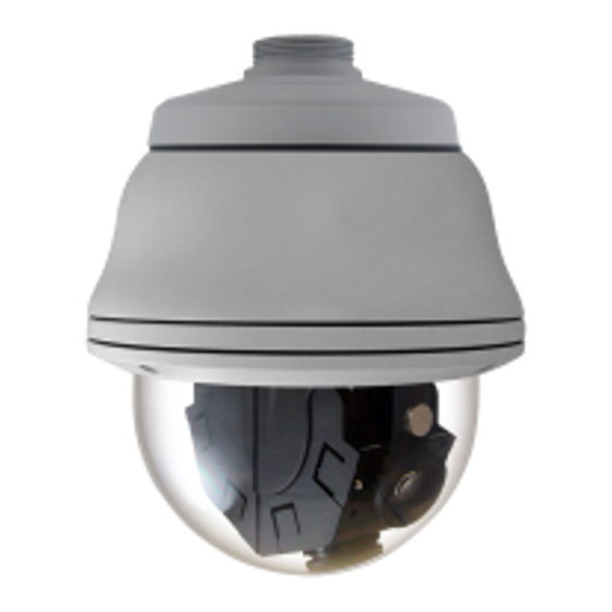
Hardware Manual Introduction List of Models This hardware manual contains the following model: 20MP Outdoor Multi-Imager Panoramic Dome with D/N, Adaptive IR, Extreme WDR, SLLS, 4 Fixed Lenses, 4 pcs 5MP Sensors www.acti.com... -
Page 8: Package Contents
Check if the following items come with the camera package. If any of them is missing, please contact your local sales agents or the Customer Help Desk (CHD). Camera Cable Gland Screw Pack Rubber Ring Wrench Drill Template Drill Template QIG& Warranty Card QIG & Warranty Card www.acti.com... -
Page 9: Physical Description
The reset button is used to restore the factory default settings of the camera, including the administrator’s password. To reset the camera, do the following: Press and hold the reset button for at least 10 seconds. The camera may take a few second to start resetting. www.acti.com... - Page 10 Connecting an ordinary microphone will dwarf sounds and will result in inaudible recording. Ethernet Port The Ethernet port connects to a network using a standard Ethernet cable. Memory Card Insert a memory card for local recording. See Insert the Memory Card Slot (Optional) on page 12. www.acti.com...
-
Page 11: Mounting Options
16 for instructions). However, there are also several mounting installation options that you can use, such as pendant mount, wall mount, pole mount, etc. For more information about mounting solutions and accessories, please visit our website (http://www.acti.com/mountingselector). Mount Types Accessories Pendant Suitable when mounting the camera on a hard ceiling. -
Page 12: Before Installation
If a memory card will be used for local recording, do the following to insert the memory card. 1. Open the dome cover. Locate the memory card slot on the base of the lens module. 2. Insert the card with the card contacts facing down the card logo. Push the card until it clicks into place. www.acti.com... -
Page 13: Installation Procedures
Below are the basic installation procedures when mounting the camera on the surface or with the use of a wall mount. Similar procedures apply when using other mounting options. For detailed information and other mounting solutions, check the website (http://www.acti.com/mountingselector). NOTE: The following pictures are for reference only, actual camera and cable connections may slightly vary. - Page 14 If the cable connections will be exposed outdoors, make sure to shield or adapt proper waterproofing methods. See Waterproof the Cable Connections on page 19. DISCLAIMER: ACTi will not be responsible for camera damage caused by water entering the cable connections. www.acti.com...
- Page 15 2. Attach the two (2) screws included in the wall mount package to secure the camera. 3. Adjust the camera tilt and viewing angle to complete the installation, see Adjust Camera Tilt and Viewing Angle on page 23. www.acti.com...
-
Page 16: Mounting The Camera Directly On The Surface
2. Using a screwdriver, loosen the four (4) screws securing the camera module to the housing. 3. Lift the camera module and pull out the cables through the mount kit and housing. 4. Remove the four (4) screws securing the mount kit to the housing, and then detach the mount kit. www.acti.com... -
Page 17: Mount The Camera
If the cable connections will be exposed outdoors, make sure to shield or adapt proper waterproofing methods. See Waterproof the Cable Connections on page 19. DISCLAIMER: ACTi will not be responsible for camera damage caused by water entering the cable connections. www.acti.com... - Page 18 Hardware Manual 4. Attach the camera module to the housing by securing the four (4) screws. 5. Adjust the camera tilt and viewing angle to complete the installation, see Adjust Camera Tilt and Viewing Angle on page 23. www.acti.com...
-
Page 19: Waterproof The Cable Connections
Crimping Tool Scissors Perform the following to waterproof the “pigtail” using the cable gland: 1. Detach the clamping nut from the cable gland: Clamping Nut Gland Body 2. Insert the clamping nut into the Ethernet cable (without connector). www.acti.com... - Page 20 4. Attach the RJ-45 connector to the cable. For pin mapping and detailed instructions, see to Attach the RJ-45 Connector for page 28 for detailed information. 5. Connect the RJ-45 connector to the camera connector. 6. Attach the gland body to the camera connector. www.acti.com...
- Page 21 Hardware Manual 7. Attach the clamping nut to the gland body to complete the cable solution. NOTE: Make sure the clamping nut is tightly attached to the cable gland body and the sealing insert is squeezed tightly. www.acti.com...
-
Page 22: Connect To Network
High PoE Injector available for purchase. Using other accessories not approved by the manufacturer may cause damage to the equipment. Accessing the Camera on page 30 for more information on how to access the Live View of the camera. www.acti.com... - Page 23 Based on the live view, you can adjust the viewing angle of the camera. 1. Loosen the tilt adjustment screws, then tilt the lens module as needed. 2. Tighten the tilt adjustment screws to fix its position. Tilt Adjustment Screws 3. Move the module base to pan the camera. www.acti.com...
-
Page 24: Other Cable Connections
Terminal Block Pin POWER DC12~24V AC24V Black Make sure to protect the cable connection inside a junction box or wrap the connection using a waterproof tape (can be purchased in hardware stores) if cable connection will be exposed after installation. www.acti.com... -
Page 25: How To Connect Digital Input / Digital Output Devices
Loosen the screw and insert the wire through the pin slot on the terminal block, then tighten the screw to secure the wire. ALARM OUT (DO) Terminal Block Pin Purple Green White ALARM IN (DI) Terminal Block Pin Blue Orange www.acti.com... - Page 26 (can be purchased in hardware stores) if cable connection will be exposed after installation. Sample below: NOTE: For more information on DI/DO connections, please refer to the article All About Digital Input and Digital Output downloadable from http://Download.acti.com?id=516. www.acti.com...
-
Page 27: How To Connect Audio Devices
If the camera is installed outdoors, be sure to wrap the audio connectors with Waterproof tape (can be purchased in hardware stores). DISCLAIMER: ACTi will not be responsible for damaged cameras due to water leakage caused by improper waterproofing of cables. Audio Input Jack... -
Page 28: How To Attach The Rj-45 Connector
3. Unwind the wires and arrange them according to the color sequence below. Stripe Orange Orange Stripe Green Blue Stripe Blue Green Stripe Brown This side up Brown 4. Straighten out the wires and use the scissors to make a straight cut ½ inch from the cut end. www.acti.com... - Page 29 5. With the RJ-45 connector tab facing down, push down the wires into the connector all the way to the end. 6. Place the connector into the crimping tool, and cinch down to secure the RJ-45 connector to the Ethernet cable. www.acti.com...
-
Page 30: Accessing The Camera
In the example below, the camera model that has just been connected to the network is successfully found. Double-click the mouse on the camera model name, the default browser of the PC is automatically launched and the IP address of the target camera is already filled in the address bar of the browser. www.acti.com... - Page 31 Search and downloand IP Utility for free from http://www.acti.com/DownloadCenter. When you launch IP Utility, the list of connected cameras in the network will be shown. See sample illustration below: The camera model name is shown on the list.
- Page 32 PC has to be configured to match the network segment of the camera. Manually adjust the IP address of the PC In the following example, based on Windows 7, we will configure the IP address to 192.168.0.99 and set Subnet Mask to 255.255.255.0 by using the steps below: www.acti.com...
- Page 33 In such case, please plug in only one camera at a time, and change its IP address by using the Web browser before plugging in the next one. This way, the Web browser will not be confused about two devices having the same IP address at the same time. www.acti.com...
-
Page 34: Access The Camera
Web browser’s address bar: http://192.168.0.100 Upon successful connection to the camera, the user interface will appear. For first time use, you need to setup the administration password. Re-type to confirm the password. www.acti.com... - Page 35 If an empty page opens, close the page and access the camera again. The user interface will prompt for the account and password for login. Type the default account: “admin”, and type the password you have just setup. For further operations, please refer to the Firmware User Manual. www.acti.com...
- Page 36 Copyright © 2020, ACTi Corporation All Rights Reserved 7F, No. 1, Alley 20, Lane 407, Sec. 2, Ti-Ding Blvd., Neihu District, Taipei, Taiwan 114, R.O.C. TEL : +886-2-2656-2588 FAX : +886-2-2656-2599 Email: sales@acti.com...
Need help?
Do you have a question about the Q75 and is the answer not in the manual?
Questions and answers