
Related Manuals for SystemAir TFE


Summary of Contents for SystemAir TFE
- Page 1 Installation, Operation and Maintenance instruction TFSR Roof fan AC/EC TFSK Roof fan AC/EC TOE Roof fan AC TOV Roof fan AC TFE Roof fan AC...
-
Page 2: Table Of Contents
..........7 13 Accessory overview ..........28 5 Electrical connection..........8 13.1 Accessory overview for TFSR fans ....28 13.2 Accessory overview for TFSK fans, TOE To do before the electrical connection ....8 fans, TOV fans, and TFE fans ...... 29 To connect the product to the power supply ............ -
Page 3: Introduction
The product is not applicable for transportation of air that The TFSR fans are supplied with a circular base plate. contains explosive, flammable or aggressive media. The product is not applicable for locations where there is a risk of The EC fans have an internal potentiometer for speed control explosion. -
Page 4: Product Overview For Tfsk Fans
1.4.2 Product overview for TFSK fans Base plate Service Lid Fan impeller Motor Connection box Name plate Mounting holes for roof curb... -
Page 5: Product Overview For Toe Fans And Tov Fans
1.4.3 Product overview for TOE fans and TOV fans Service lid with motor bracket Fan impeller Position of connection box and name plate with air flow direction arrow. The TOE fan is delivered with connection box, the TOV fan is delivered without. Base plate Casing Screws attaching the lid to the casing... -
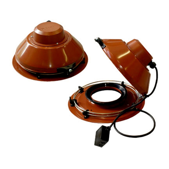
Page 6: Product Overview For Tfe Fans
1.4.4 Product overview for TFE fans Name plate with airflow direction arrow Mains isolator switch Fan impeller and motor Base plate Duct connection Lid lock Motor bracket Motor bracket screw 10. Screw for opening of lid Name plate... -
Page 7: Type Designation
Note: Information that is necessary in a given situation. Use a mobile device to scan the scannable code and go to the Systemair documentation portal for more documentation and document translations. -
Page 8: Safety Instructions
• Always use spare parts from Systemair. • Sound levels exceeding 70 dB(A) may occur depending on model and size. Visit www.systemair.com for more de- tailed information about your product. • The product is not to be used by persons, including chil-... -
Page 9: Installation
Systemair recommends to install the product together with a roof curb TOS or TOB. The roof curbs are available as accessories. If a roof curb is used, refer to www.systemair.com for in- structions how to install roof curb TOS or TOB. -
Page 10: Electrical Connection
Connect the primary electric supply to the connection Electrical connection box of the product. Refer to 12.3 Wiring diagrams page 18. For the TFE fan, loosen the screws that hold the mo- To do before the electrical tor bracket to access the terminals that are attached to the motor bracket. -
Page 11: Speed Controller For Ec Motors
EC motors have an integrated motor protection. Reset the The commissioning report is found at www.systemair.com. motor protection by disconnecting the fan from power supply for 60 seconds. To do before the commissioning •... -
Page 12: Operation
EC motors must be set to ON/OFF via the control input. To stop the product via mains supply decreases the life time of the motor. Systemair recommends to install external speed controller for easy access to control the input signal. -
Page 13: To Clean The Product
Spare parts • For information about spare parts, send an e-mail to support@systemair.com. • For more information about spare parts, contact Systemair support. • Always use spare parts from Systemair. • When you send an order for spare parts, include the serial number of the product. -
Page 14: Troubleshooting
Troubleshooting Note: If you cannot find a solution to your problem in this section, speak to Systemair technical support. Problem Cause Solution The fan impeller is not correctly Speak to Systemair technical support. balanced. There is dirt on the fan impeller. - Page 15 This is not applicable for EC motors or 3–phase AC motors. There is blockage in the motor. Speak to Systemair technical support. Defective motor winding. If it is possible, measure the resistance to do a check of the motor winding.
-
Page 16: Disposal
Disposal 10.1 To disassemble and discard the parts of the product The product follows the WEEE directive. This symbol on the product or the packaging of the product shows that this Disconnect and disassemble the product in the opposite product is not domestic waste. The product must be recycled sequence of electrical connection and installation. -
Page 17: Warranty
12.1 Technical data overview Max. temperature of transported air, °C Max. ambient temperature, °C Refer to the data sheet in the online catalogue at www.systemair.com. Sound pressure, dB IP class Voltage, current, frequency, enclosure Refer to the name plate. Refer to 1.5 Name plate page 4... -
Page 18: Product Dimensions For Tfsk Fans
ØE TFSR 200 TFSR 315 L** TFSR 315 M** TFSR 315 Sileo TFSR 160 EC Sileo TFSR 200 EC Sileo ** after the product name means that the product is sold outside EU. 12.2.2 Product dimensions for TFSK fans Note: If the unit of measure is not specified, the dimensions are given in millimetres. -
Page 19: Product Dimensions For Tfe Fans
ØF ØI ØJ M20- TOE /TOV (8x) x1.5 (4x) (8x) 355–4 M20- TOV 450– (8x) x1.5 (4x) (8x) 12.2.4 Product dimensions for TFE fans Note: If the unit of measure is not specified, the dimensions are given in millimetres. TFE 220 M 209.5 209.5... -
Page 20: Wiring Diagrams
Brown Black Grey Green/Yellow 12.3.1 Wiring diagrams for AC fans TFSR fans TFSK fans 1–phase 230 V TFSR 125 M TFSK 125 M TFSR 125 XL TFSK 125 XL Sileo Sileo TFSR 160 Sileo TFSK 160 Sileo TFSR 200 TFSK 200... -
Page 21: Wiring Diagrams For Ec Fans
Note: An internal potentiometer is installed on the terminal block from the factory. Remove the internal potentiometer when you use an external speed controller for the EC fan. TFSR EC fans TFSK EC fans 1–phase 230 V TFSR 160 EC... - Page 22 REE — Thyristor REE 1 and REE 2 - Surface mounting or with flush mounting casing included. REE 4 - Surface mounting. Note: Starting currents must be considered when you select the speed controller type. Products that are used with this speed controller must have a built-in overheating protec- tion and must be designed for thyristor speed control.
- Page 23 Relay connection. There is always 230 V between ~ and N when the transformer knob is in one of the positions 1–5. Mains supply C. Earth D. Fan Thermostat Motor protection. If the motor protection is not in use, Tk must be looped together. FRQ5S-E-6A Frequency converter with built-in all-pole sine filter and 5-step switch.
- Page 24 RTRD A 3-phase transformer that controls the fan speed by altering the supply voltage in five fixed steps. The steps are adjusted by using the control knob on the front of the unit. RTRD2-7 FS FS TK TK 230 V AC If the function is not necessary, the terminals must be bridged Contact rating, 230 V AC/maximum 1 A C.
-
Page 25: Wiring Diagrams For Speed Controllers For Ec Motors
RTRDU Manual 5–step transformer with motor protection — a 3–phase transformer that controls the fan speed by altering the supply voltage in five fixed steps. The steps are adjusted by using the control knob on the front of the unit. RTRDU FS FS TB TB... - Page 26 MTP 20 MTP 20 1/Vdc+ +10V 4/Vout 0...10V 2/Vdc- 3/Vout- EC-Basic EC-Basic 1/IN Vac 230V AC 2/IN Vac +10V 4/Out 0...10V 5/GND MTV–1/10 MTV 1/010 1/IN Vac 230V AC 2/IN Vac +10V 4/Out+ 0...10V 5/Out- S-5EC/FRQ MTP 10 +10V 0...10V EC-Vent optional IN/RPM...
-
Page 27: Wiring Diagrams For On/Off Controls For Ec Motors
12.3.5 Wiring diagrams for ON/OFF controls for EC motors CO2RT-R(-D) Supply +10V 24V AC Neutral 0...10V Common Relay NO Relay NC Din1 IR24–P +10V 24V AC or DC Neutral 0...10V Common Relay NO Relay NC Din1 12.3.6 Wiring diagrams for demand control for EC motors EC Basic EC Basic-T for temperature control EC-Basic... - Page 28 EC-Vent Demand control for up to 5 external sensors, 2 fans, damp- ers, heaters and coolers. The EC vent system has 2 units. The control board (CB) and the room unit (RU). Connect the fan to the control board and optional IN/RPM TACH...
- Page 29 Control Board (CB) ALARM FAN OUT3 OUT2 OUT1 DEBUG PT1000 +24VDC PT1000 Y +0-10V PT1000 Br + 24VDC N out N in L out L in Mains supply, 230 V 1~AC (10 A) Analogue sensor (for example, pressure sensor) C. Analogue sensor (for example, pressure sensor type PT1000) D.
-
Page 30: Accessory Overview
Mains supply 10..24 V DC Output 0..10 V Pressure connections Voltage input for switch on Setpoint 1/Setpoint 2 Accessory overview 13.1 Accessory overview for TFSR fans Note: For more information about accessories, refer to www.systemair.com or speak to Systemair technical support. -
Page 31: Accessory Overview For Tfsk Fans, Toe Fans, Tov Fans, And Tfe Fans
TOB: Roof curb with curbed covering plate TOS: Roof curb with flat covering plate 13.2 Accessory overview for TFSK fans, TOE fans, TOV fans, and TFE fans Note: For more information about accessories, refer to www.systemair.com or speak to Systemair technical support. - Page 32 FDS: Flat roof socket FDS-L: Flat roof socket (large) TG: Roof curb STG: Connection plate – base plate ASK: Inflow box SSD...
-
Page 33: Eu Declaration Of Conformity
Industrivägen 3 739 30 Skinnskatteberg Sweden declare under our sole responsibility that the products Type/Model TFSR, TFSK, TOE, TOV, TFE Identification Serial numbers dating from 2018 and onwards fulfils the relevant provisions of following directives and RoHS Directive 2011/65/EU standards... -
Page 34: Declaration Of Conformity
SE-73930 Skinskatteberg Sweden declare under our sole responsibility that the products Type/Model TFSR, TFSK, TOE, TOV, TFE Identification Serial numbers dating from 2018 and onwards fulfils the relevant provisions of following directives and The Restriction of the Use of Certain Hazardous... - Page 36 © Copyright Systemair AB All rights reserved Systemair AB reserves the rights to alter their products without notice. This also applies to products already ordered, as long as it does not affect the previously agreed specifications. Original instructions 2022-04-05...
Need help?
Do you have a question about the TFE and is the answer not in the manual?
Questions and answers