
Subscribe to Our Youtube Channel
Related Manuals for SystemAir Topvex SF03 Series


Summary of Contents for SystemAir Topvex SF03 Series
- Page 1 Topvex SF02-SF12 Air Handling Unit Installation instructions Document in original language | 130324 · A004...
- Page 2 © Copyright Systemair AB All rights reserved E&OE Systemair AB reserves the rights to alter their products without notice. This also applies to products already ordered, as long as it does not affect the previously agreed specifications. 130324 | A004...
-
Page 3: Table Of Contents
Contents Declaration of Conformity .........1 Warnings............2 Product information .........2 General ..........2 Technical data ........3 3.2.1 Dimensions and weight ....3 3.2.2 Electrical data ......5 Transport and storage ......6 Installation.............6 Unpacking ..........6 Where/how to install ......6 Installing the unit........7 4.3.1 Mounting brackets......8 4.3.2 Installing procedure ....8 Connection ...........9... -
Page 5: Declaration Of Conformity
Declaration of Conformity | Declaration of Conformity Manufacturer Systemair Sverige AB Industrivägen 3 SE-739 30 Skinnskatteberg SWEDEN Office: +46 222 440 00 Fax: +46 222 440 99 www.systemair.com hereby confirms that the following products: Air handling units Topvex SF02 Topvex SF03... -
Page 6: Warnings
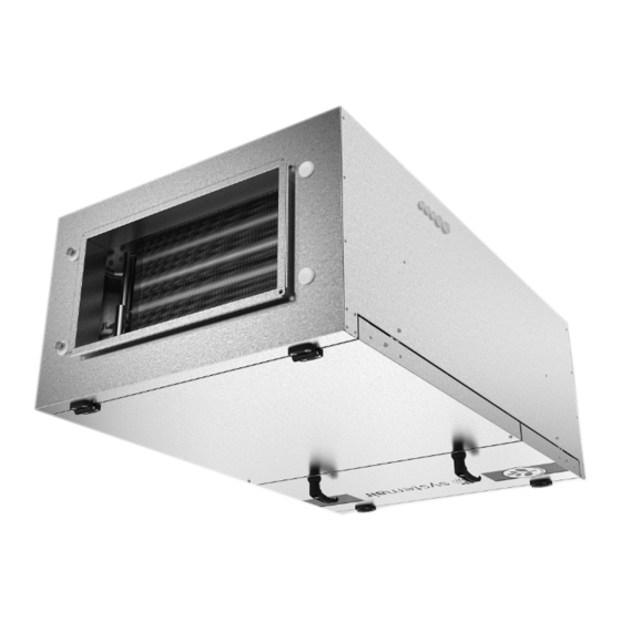
Product information General This installation manual concerns air handling unit type Topvex SF manufactured by Systemair Sverige AB. The units in- clude the following model options: • Model: Topvex SF02, Topvex SF03, Topvex SF04, Topvex SF06, Topvex SF08 and Topvex SF12. -
Page 7: Technical Data
Product information | Technical data 3.2.1 Dimensions and weight øJ ø22 Fig. 1 Topvex SF02-Topvex SF03 Dimension (mm) Model Topvex SF02 1463 1366 Topvex SF03 1550 1454 øJ Model Weight, kg Topvex SF02 Topvex SF03 130324 | A004... - Page 8 | Product information ø22 Fig. 2 Topvex SF04-Topvex SF12 Dimensions (mm) Model Topvex SF04 1497 Topvex SF06 1497 Topvex SF08 1497 Topvex SF12 1546 1011 size S08 and S12 only in HW Model Weight, kg Topvex SF04 1454 Topvex SF06 1454 Topvex SF08 1454...
-
Page 9: Electrical Data
Product information | 3.2.2 Electrical data Model Fans (W tot.) 230V 1~ and El Heating battery (kW tot.) Fuse (mains) (A) for 400 V 3N~ 230 V 1~ and 400 V 3x16 Topvex SF02 EL 4,5 kW 3x16 Topvex SF02 EL 9 kW Topvex SF02 HWL, HWH 3x16 Topvex SF03 EL 7,7 kW... -
Page 10: Transport And Storage
Unpacking Verify that all ordered equipment are delivered before starting the installation. Any deviation from the ordered equip- ment must be reported to the supplier of Systemair products. Where/how to install Topvex SF02-SF12 can be installed outside if weather protected. An outdoor air section, ODS is available as accessory. -
Page 11: Installing The Unit
Installation | Installing the unit Caution Make sure that the hatch to the electrical connection box doesn’t fall down during installation in false ceiling. The unit can be installed in the positions shown in figure 3. When the HW units are mounted horizontally on a wall, always make sure that the water pipe connections are above the battery, so the HW battery can be properly de-aired. -
Page 12: Mounting Brackets
| Installation 4.3.1 Mounting brackets Together with the Topvex SF unit follows 4 mounting brackets that allows the unit to be mounted according to illustra- tion figure 3 and figure 4. Fig. 4 Model 1235 Topvex Topvex SF02EL/HW 1322 Topvex Topvex SF03 EL/HW 1322 Topvex Topvex SF04 EL/ HW 1322... -
Page 13: Connection
Installation | Connection 4.4.1 Ducting Air to and from the unit is led through a duct system. To ensure long life and satisfactory cleaning possibilities, ducts made of galvanised steel are highly recommended. To obtain low energy consumption and required airflow, the duct system should be commissioned for low air speeds and low pressure drop. -
Page 14: Electrical Connection Box, Components
| Installation 4.4.2 Electrical connection box, components Danger • Make sure that the mains power supply to the unit is disconnected before performing any maintenance or electrical work! • All electrical connections must be carried out by an authorized installer and in accordance with local rules and regulations. -
Page 15: External Connections
Installation | 4.4.3 External connections Terminal block Description (GB) Remark Ground Earthed neutral (supply voltage) Phase (supply voltage) Used for phase 230V 1~ if the unit has this mains power supply 400V 3~ 400V 3~ Phase (supply voltage) 400V 3~ Phase (supply voltage) 24V AC Mains power supply (Water valve actuator) -
Page 16: Temperature Sensor, Supply Air And Outdoor Air Damper
| Installation 4.4.4 Temperature sensor, supply air and outdoor air damper Mount the enclosed duct sensor in the supply air duct. Fig. 7 Temp sensor and damper Sensor, supply air Motorized damper, outdoor air (accessory) The damper (accessory) is also preventing the hot water battery from freezing by closing when the returning water in the battery is below a set temperature, +8 °C, alternatively if the supply air temperature drops below a set temperature (adjustable). -
Page 17: Electrical Heater
Installation | Table 2 From Menu overview (Operating and Maintenance Instruction) → Log on → Access rights Log on Log on to service level by entering Enter password xxxx a 4-digit code. After reaching the Actual level: None desired level go back with “LEFT” arrow (press 2 times) on the control panel. -
Page 18: Bms Connection
| BMS Connection BMS Connection Communication possibilities for controller E283 WEB. • RS485(Modbus): 50-51-52 or 60-61-62 • RS485(BACnet): 50-51-52 or 60-61-62 • RS485(Exoline): 50-51-52-53 or 60-61-62-63 • TCP/IP Exoline • TCP/IP Modbus • TCP/IP WEB • TCP/IP BACnet Fig. 8 BMS connection on the controller Control panel General information The control panel is delivered connected to the Corrigo control unit situated in the electrical connection box. -
Page 19: Dimensions
Control panel | Dimensions Fig. 9 Control panel dimensions Dimensions (mm) Position 115.0 94.0 26.0 c/c 60.0 50.5 130324 | A004... -
Page 20: Installation
| Control panel Installation 1. Find an appropriate place to install the control panel. Maximum length between control panel and unit is 100 m. 2. If needed, drill two holes in the wall to hang the control panel (center to center: 60 mm) (pos.1, figure 10). Fig. - Page 21 Control panel | 130324 | A004...
- Page 22 | Control panel 130324 | A004...
- Page 23 130324 | A004...
- Page 24 Systemair Sverige AB Industrivägen 3 SE-739 30 Skinnskatteberg, Sweden Phone +46 222 440 00 Fax +46 222 440 99 www.systemair.com...
Need help?
Do you have a question about the Topvex SF03 Series and is the answer not in the manual?
Questions and answers