Table of Contents
Advertisement
SAP 100074
Operating Manual
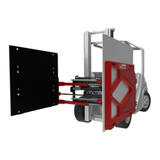
Appliance Clamp
T 413G-1L, T 403G-1L
T 413G-2L, T 403G-2L
T 414-1L, T 404-1L
T 414-2L, T 404-2L
T413-1
T414-1
T413G-1L
T403G-1L
T413G-2L
T403G-2L
T414-1L
T404-1L
T414-2L
T404-2L
Edition 04/17
T 413-1, T 414-1
Appliance Clamp with sideshift and arms with rubber covering for „white
appliances", 1 arm swivelling
Appliance Clamp without sideshift and arms with rubber covering for „ white
appliances", 1 arm swivelling
Appliance Clamp with sideshift and arms with rubber covering for „ white
appliances", 1 arm swivelling, 2 contact pads per arm
Appliance Clamp without sideshift and arms with rubber covering for „ white
appliances", 1 arm swivelling, 2 contact pads per arm
Appliance Clamp with sideshift and arms with rubber covering for „ white
appliances", both arms swivelling
Appliance Clamp without sideshift and arms with rubber covering for „ white
appliances",both arms swivelling
Appliance Clamp with sideshift and arms with rubber covering for „ white
appliances", both arms swivelling, 2 contact pads per arm
Appliance Clamp without sideshift and arms with rubber covering for „ white
appliances ", both arms swivelling, 2 contact pads per arm
Original Operating Manual
en
1
Subject to modifications
Advertisement
Table of Contents

Related Manuals for KAUP T413-1


Summary of Contents for KAUP T413-1
- Page 1 SAP 100074 Operating Manual Appliance Clamp T 413G-1L, T 403G-1L T 413G-2L, T 403G-2L T 413-1, T 414-1 T 414-1L, T 404-1L T 414-2L, T 404-2L T413-1 Appliance Clamp with sideshift and arms with rubber covering for „white T414-1 appliances“, 1 arm swivelling T413G-1L Appliance Clamp without sideshift and arms with rubber covering for „...
-
Page 2: Table Of Contents
Operating Manual Contents Page Introduction ............................. 4 Working with this manual ......................4 Warning notes and symbols ..................... 4 Copyright ..........................4 CE-Mark ........................... 5 Qualified and authorised personnel ..................5 Warranty claims based on defects ................... 5 Limits of applicable use ......................5 Safety aspects ............................ - Page 3 Orders for spare parts Export 0049 (0) 6021 865344 0049 (0) 6021 865348 Outside of normal business hours the Kaup – Service Hotline is available to you 365 days a year: 0049 (0) 172 6295 297 Monday - Friday: 17:00 – 7:00 Uhr Saturday and Sunday: 8:00 –...
-
Page 4: Introduction
This documentation including all parts is copyrighted. Any use or change outside the narrow limits of copyright law without permission from KAUP GmbH & Co KG is forbidden and liable to prosecution. This applies, in particular, to reproduction, translation, microfilming as well as storage and processing in electronic systems. -
Page 5: Ce-Mark
They are assigned tasks by the equipment owner. Warranty claims based on defects KAUP shall not be liable for any damage to the equipment resulting from: Improper use / operation. Modifications to components. -
Page 6: Safety Aspects
Operating Manual Safety aspects As the user, extend the safety instructions with generally applicable, legal and other measures that ensure a safe and environmentally friendly operation of the attachment. Pay close attention to all safety- and danger-related signs on the attachment and in this operating manual. -
Page 7: Design
Operating Manual Design Clamp with mounting A clamp consists of a clamp body (1) on which conduits (2) are mounted. Cylinders (4) move the conduits (2), which are equipped with sliders (3). Sideshift components (5, 6) or hooks (7, 8) are optionally attached to the clamp body (1). -
Page 8: Proper Use Of The Equipment
Operating Manual The right or left arm of models T403G-1L / T413G-1L and T403G-2L / T413G-2L consists of conduits (1) and a rigid arm (3). For the T403-1 / T413-1 model, this applies to the right-hand or left-hand arm. The left arm consists of conduits (1) onto which an arm carrier (2) is welded. -
Page 9: Installation And Checking Out
Operating Manual Installation and checking out Installation Installation and commissioning should be performed by qualified and authorised personnel only. Pay attention to a sufficient load-carrying capacity of the lifting means. The following are examples of preferred lifting means: Capacity 250 kg/M16 1200 kg/M16 2000 kg/M16 Part-no. - Page 10 Operating Manual Hoist the attachment at the positions indicated (1). Demount the lower hooks (2). Mount the attachment on the fork carriage of the lift truck (3). Check that the attachment is correctly seated in the centre lock (4). ...
-
Page 11: Pressure Plate Toe-In / Preload Adjustment As Necessary And Depending On Attachment Design
Operating Manual 4.1.2 Pressure plate toe-in / preload adjustment as necessary and depending on attachment design Adjust the toe-in (a) or preload (b) by loosening the screws (1). Use the adjusting screws (2) to set the pressure plate (3) to the desired position. ... -
Page 12: Checking Out
Operating Manual Checking out KAUP-attachments are delivered pre-lubricated. If the attachment has been in storage for a longer period, we recommend that it be lubricated again before being placed in service. See 6. Maintenance and onwards. Failure of the safety devices (e.g. the pressure relief valve and the non-return valve) and incorrect connection of the controls to the actuators can cause malfunctioning of the attachment and damage to it. - Page 13 Operating Manual The synchronization is adjustable by means of two throttles on the bottom of the cylinders. Setting the clamping pressure with a pressure limiting valve Attachments are adjusted ex-factory to a pressure of 160 bar. A change in pressure is necessary only, if the load slips or is damaged.
-
Page 14: Operation
Operating Manual Operation General At least once per working shift, the machine and equipment must be inspected for visible damage and defects. Repeat faults to your superior and have them rectified without delay. Be aware of persons present in the area where you are working or driving and ensure that they are not endangered. -
Page 15: Maintenance And Servicing
Operating Manual Maintenance and servicing General Regular maintenance is essential to ensure reliable operation and long service life of the KAUP attachment Ensure that maintenance and servicing are performed by qualified and authorised personnel only. Lubrication and cleaning work on the attachment may also be performed by the lift truck operator. -
Page 16: Significant Modification
The EC Declaration of Conformity is invalidated by a significant modification of the attachment. Modifications to the attachment may only be made with prior approval by the manufacturer. Schedule for routine maintenance and lubricants Lubricants approved and recommended by KAUP Greases Note... -
Page 17: Clamp
Operating Manual 6.3.1 Clamp 6.3.2 Mounting (with or without sideshift) Original Operating Manual... - Page 18 Operating Manual Daily Check all lines, hoses and connections for leakage and damage. After 50h / every 500h thereafter Check: Screws (11) on the sideshifter housing (12). Screws (17) on the upper hooks (18). Screws (13) on the lower hooks (14). Screws (19) on the spacers (20).
-
Page 19: Clamping Arms, Model T403G-1L / T413 G-1L And T403G-L / T413G-L
Operating Manual Replace defective supporting rollers (15) in the hooks (14) by removing the screws (13). Using suitable hoisting gear tilt the clamp body (7) forwards away from the fork carriage on the lift truck. Remove the bolts in the hooks, remove the defective supporting rollers (15) and replace them with new ones. -
Page 20: Right-Hand Or Left-Hand Appliance/Polystyrene Clamp Arms For T403-1 / T413-1 And T404-1 / T414-1
Operating Manual 6.3.4 Right-hand or left-hand appliance/polystyrene clamp arms for T403-1 / T413-1 and T404-1 / T414-1 models As necessary Replace the worn rubber covering (1). worn bars (2), by removing the screws (3). Original Operating Manual... -
Page 21: Clamping Arms Right And Left, Model T404-1L / T 414-1L
Operating Manual 6.3.5 Clamping arms right and left, model T404-1L / T 414-1L After 50h / every 500h thereafter Check: Screws (11) of the bars (2) and (3). Screws (12) and nuts (13) of the swing bearings. Screws (10) on the pressure plates (4), bars (2) and wear-off bars (6). Screws (15, 16) on the wear-off-bar (7) and cover sheets (5). -
Page 22: Clamping Arms Right And Left, Model T404-2L / T414-2L
Operating Manual As necessary Renew the worn covering (8) or wear-off bar (6) by removing the cover plate (5) and screws (16). Remove the screw (10) and bushes (9). Take off the pressure plate (4) to the side. Replace the covering (8) or wear-off bar (6). If the wear is only slight, you can also turn the pressure plate (4) and wear-off bar (6) through 180°. - Page 23 Operating Manual After 50h / every 500h thereafter Check: Screws (10) on the rocker arms (3). Screws (12) and nuts (13) on the rocker arms (2). Screws (11) and nuts (13) on the rocker arms (3). Screws (10) and nuts (19) on the wear-off-bar (6). Screws (15, 16) on the wear-off-bar (7) and cover sheets (5).
-
Page 24: Right-Hand Or Left-Hand Swivelling Appliance/Polystyrene Clamp Arms For T403-1 / T413-1 And T404-1
Operating Manual 6.3.7 Right-hand or left-hand swivelling appliance/polystyrene clamp arms for T403-1 / T413-1 and T404-1 / T414-1 models After 50h / then every 500h Check the screws (1) at the strips (2), (3) at the spring plate (4) and spacer (5). Replace loose or damaged screws. -
Page 25: Pressure Plate Toe-In / Preload Adjustment
Operating Manual As necessary Renew worn or damaged strips (2) by removing the screws (1) and replacing the strip (2). Reinstall the screws (1). Renew worn or damaged pin (6) in the arm (9) by removing the cotter pin (10) and washer (11). -
Page 26: Identification Plate And Caution Board
Operating Manual 6.3.9 Identification plate and caution board Number Description KAUP order number only by quality- Identification plate department Before putting into operation carefully read and take note of the 0100016401 operating and security instructions. Never reach into the unit as long... -
Page 27: Troubleshooting
Operating Manual without, engraved in KAUP – order number ko xxxxxx the material Troubleshooting Troubleshooting should only be performed by qualified and authorised personnel. Fault Possible cause Correction Clamp Opening and closing WE throttles on the cylinder Adjust the WE throttles on... -
Page 28: Disposal
Operating Manual Fault Possible cause Correction Sideshifter When shifting Pressure supplied by the Too slow Increase pressure at the FFZ FFZ too low Bore of the throttle valve is Re-bore the throttle valve or too small replace it with a larger one Jerky shifting action Supporting roller defective Replace supporting roller... -
Page 29: Decommissioning And Storage
Store the attachment in a clean, dry environment. Spare parts list (not part of the Operating Manual) EC Declaration of Conformity (Summary) KAUP GMBH & Co. KG • Braunstraße 17 • D-63741 Aschaffenburg we hereby declare that the machinery...
Need help?
Do you have a question about the T413-1 and is the answer not in the manual?
Questions and answers