RADEMACHER 2610 Mounting And Operating Instruction
Tube motor control
Source: rademacher.de

Related Manuals for RADEMACHER 2610


Summarization of Contents
Mounting and Operating Instruction
Product Overview
Introduces the Troll comfort device and its purpose.
Welcome and Instruction Purpose
Customer Gratitude and Product Introduction
Thanks the customer for choosing the quality product and explains the instruction's scope.
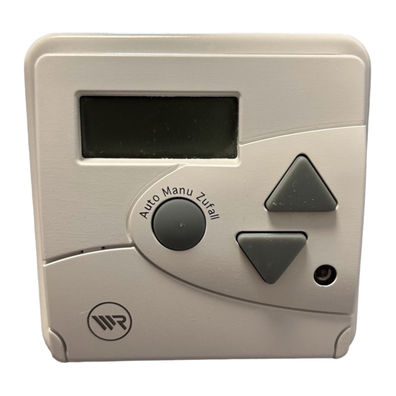
Overall Device View
Identification of Key Components
Labels and illustrates the main parts of the Troll device.
Safety Signs and Warnings
Electrical Shock Hazard
Symbol indicating danger to life from electric shock and required safety measures.
General Safety Admonition
Emphasizes observing all safety instructions marked with this symbol.
Important Content Notes
Draws attention to perfect function of important content via comments.
Correct Application Guidelines
Permitted Use
Specifies use for connecting and controlling tube motors with end limit switches.
Operating Environment
Details operating conditions, requiring dry rooms and specific power supply.
Incorrect Usage and Warranty
Prohibited Applications
States it's forbidden to connect or control other consumers than specified.
Use of Original Parts
Stresses using only original manufacturer parts for functionality and warranty coverage.
Electrical Safety Procedures
Authorized Electrician Requirement
Electrical connection must be performed by an authorized electrician following local regulations.
Power Disconnection
Ensure power line is idle and secured before electrical connection to prevent accidental restart.
Appliance Safety and Repairs
Defective Appliance Risk
Warns of dangers from defective appliances, including electric shock and damage.
Professional Repair Necessity
Emphasizes that repairs must be done by authorized service to avoid hazards and destruction.
Functional Description Overview
Device Purpose
The Troll controls tube motors and mounts in flush boxes using enclosed housing.
Available Operating Modes
Lists manual, automatic (standard, weekly, sun, twilight, random), and additional modes.
LCD Display Information
Displayed Data
LCD shows operating mode, functions, current time, and switching times.
Manual Operation Guide
Basic Manual Control
Roller shutter can be opened, closed, or stopped using the UP/DOWN keys.
Manual Control Methods
Manual operation is possible via appliance keys, external switch, or IR sender.
Automatic Program Modes
Standard Program Setup
Sets a fixed opening and closing time valid for all weekdays.
Weekly Program Setup
Allows individual daily adjustment of opening and closing times for each weekday.
Advanced Automatic Modes
Random Mode Operation
Delays adjusted switching times by up to 30 minutes randomly.
Disabling Automatic Mode
Automatic mode can be switched off; Sun/Twilight functions remain active.
Sun and Twilight Automation
Sensor-Based Control
Controls shutter based on brightness using a light sensor connected via plug.
Sun Automatic Functionality
Enables automatic shutter movement based on adjusted brightness threshold values.
Sun Automatic Operation Details
Shutter Response to Sun
Shutter lowers after 10 min if daylight exceeds limit, moves up after 25 min to release sensor.
Low Light Shutter Action
With decreasing brightness, the roller shutter moves to the upper limit stop.
Twilight Automatic Operation
Twilight Triggered Closing
Shutter lowers to bottom stop for 10 sec when twilight value is exceeded.
Twilight Opening Condition
Shutter opens at adjusted time or via manual UP command.
Twilight Closing Time Setting
Adjust automatic closing time to be after twilight entry for downward movement.
Pre-Installation Checks
Installation Housing Use
Assembly and connection must use the enclosed installation housing with bottom-side terminals.
Tube Motor Limit Stops
Crucial to adjust tube motor limit stops before final electrical connection for proper function.
Electrical Connection Safety
Authorized Electrician Requirement
Electrical connection must be performed by an authorized electrician, adhering to page 8 safety instructions.
Wiring Integrity
Warns faulty wiring can cause short circuits and appliance destruction; observe pin connection sequence.
Electrical Connection Diagram
Basic Circuit Overview
Provides a basic circuit diagram illustrating the electrical connections.
Mounting Requirements and Integration
Required Mounting Parts
Requires a 58-flush socket and an enclosed covering frame for installation.
Switch Program Compatibility
Troll integrates with commercial switch/frame programs or uses enclosed frames.
Step-by-Step Mounting Procedure
Preparation and Connection
Put power supply idle, perform electrical connection, mount housing, and attach frame.
Light Sensor Installation
Insert light sensor plug and guide cable; later mounting is also possible.
Final Power Up
Insert Troll carefully and switch on the power supply to complete installation.
Mounting Construction Details
Exploded View of Components
Illustrates the assembly of the covering frame, Troll control, and installation housing.
Light Sensor Mounting Illustration
Sensor Connection Diagram
Shows the connection of the light sensor to the Troll device.
Optimal Light Sensor Placement
Sensor Mounting on Window
Fasten sensor with suction cup on window pane to measure brightness.
Positioning for Automation
Choose sensor position for correct triggering of Sun and Twilight automatic functions.
Sensor Handling Precautions
Avoid damaging sensor/cable; remove using handle, do not buckle cable.
Adjustment Settings and Key Meanings
Time Exceedance Indication
Current time appears if no adjustments are made for an extended period.
Deactivating Time Programs
Set requested time to 0:00 to prevent execution of the corresponding control command.
Understanding Key Symbols
Explains symbols for pressing/tipping a key and releasing a key.
Initial Device Start-up
Power Connection and Initial Display
Connect power; if dashes appear, press CLOCK; if time appears, perform software reset.
Operational Readiness
Troll is ready for operation after switching on, provided limit stops are adjusted.
Setting the Current Time
Time Adjustment Procedure
Adjust current time using SET key; figures change in fast forward running of time.
Fine-Tuning Time Control
Details on holding/tipping keys for slow/fast forward/backward time adjustment.
Seasonal Time Adjustment
Summer/Winter Time Change
Change internal clock forward/backward by 1 hour for seasons.
Initiating Time Change
Procedure to change between summer and winter time using the weekly key.
Standard Program: Opening Time
Setting General Opening Time
Press and hold UP+SET keys for forward time running to set general opening time.
Key Operation for Time
Details for slow/fast forward/backward time adjustment using UP and SET keys.
Standard Program: Closing Time
Setting General Closing Time
Press and hold SET+DOWN keys for backward time running to set general closing time.
Key Operation for Time
Details for slow/fast forward/backward time adjustment using DOWN and SET keys.
Weekly Program Setup
Entering Program Input Mode
Activate weekly program input by pressing 1/7 and SET keys.
Setting Current Weekday
Use SET key to cycle through weekdays until the current day is displayed.
Weekly Program: Daily Times
Adjusting Daily Switching Times
Set individual switching times for each weekday; program restarts from Monday.
Program Time Inheritance
Weekly programs adopt standard times; adjustments are analogous to standard time settings.
Weekly Program: Monday Adjustment
Setting Monday Opening Time
Adjust Monday's opening time; closing time is shown sequentially.
Key Sequence for Monday
Use UP key to call adjustment, UP+SET to set opening time.
Weekly Program: Navigation and Termination
Advancing to Next Day
Press 1/7 key to move to the next weekday for adjustment.
Exiting Program Setup
Press 1/7 key multiple times to pass all input points and terminate adjustments.
Additional Weekly Times
Define two mutual weekly switching times valid daily, in addition to individual times.
Activating the Weekly Program
Entering Program Activation Mode
Activate program by pressing 1/7 key once; display shows 0:00.
Finalizing Program Setup
Leave input mode after adjustments; weekly program is now active.
Modifying Weekly Program Times
Adjusting Daily Times
Control and amend daily switching times using UP/DOWN keys when weekly program is active.
Viewing and Amending Times
Call opening time (e.g., Mon 7:30) with UP key; amend current daily time as per pages 30/31.
Switching Between Program Modes
Mode Change Mechanism
Pressing the weekly key toggles between operating modes.
Standard Program Activation
The Standard program becomes active after pressing the weekly key for 2 seconds.
Sun Automatic Configuration
Controlling Sun Automatic
Switch the sun automatic function on or off by repeatedly pressing the sun symbol key.
Setting Brightness Limits
Adjust the limiting value for sun intensity; higher sun increases the measured value.
Sun Automatic Status and Interruptions
Interpreting Sun Symbol
OFF=off, ON=on, FLASHING=active, indicating sun automatic status.
Events Interrupting Sun Program
Program interrupted by manual operation, other automatic functions, IR remote, or external switch.
Setting Sun Automatic Thresholds
Adopting Current Brightness
Set the current brightness as the limiting value for shutter lowering.
Modifying Brightness Thresholds
Amend adjusted limiting value by pressing and holding or additionally pressing UP/DOWN keys.
Twilight Automatic Configuration
Controlling Twilight Automatic
Switch twilight automatic on/off and adjust limiting value using the moon key.
Twilight Restart Delay
After manual opening, twilight automatic resumes action after approximately 1 hour.
Manual Operation Overview
Manual Priority
Manual operation has priority over automatic modes and is always possible.
Controlling Shutter Movement
Use UP/DOWN keys to move shutter to limit stops; short press stops movement.
Manual Operation Modes
Normal Operation Mode
Shutter moves to adjustment after each key press.
Tipping Operation Mode
Shutter moves continuously while the key is pressed.
Mode Change Warning
Switching to tipping mode requires a software reset to return to normal operation.
Switching to Tipping Mode
Physical Mode Change
Change mode by shorting a connecting path on the backside of the Troll with a screwdriver.
Tipping Mode Detailed Operation
Single Key Press
Roller shutter opens/closes until the key is released.
Sustained Key Press
Shutter moves to upper/bottom limit stop with a 3-second press.
Stopping Shutter Movement
Tipping the key stops the roller shutter's movement.
External Switch Control Options
External Switch Integration
Troll can be operated using an external switch or control unit.
Switching Sequence Logic
UP press moves shutter up, tip stops; DOWN press changes direction.
Parallel Control Capability
Multiple Trolls can be connected parallel for synchronized remote control.
IR Remote Control Features
Remote Control Components
Identifies key parts of the remote like Control-LED, Collective Key, Channel Keys, and Sender-Eye.
IR Remote Control Modes
Normal Remote Operation
Shutter moves in the selected direction; pressing the key again stops the movement.
Tipping Mode via Remote
Shutter moves as long as the key is pressed, as detailed on page 46.
IR Remote Multiple Channel Setup
Grouping Shutters
Allocate channel numbers to combine multiple roller shutters into groups for simultaneous control.
Activating Multi-Channel Mode
Activate multiple channel mode by pressing the SET key for 4 seconds.
Assigning Channel Numbers
Press the desired channel key (1-5) within approximately 4 seconds to allocate it.
IR Remote Channel Management
Executing Group Commands
Press channel key, then within 3 min send command to execute control in multiple channel mode.
Deleting Channel Allocation
Delete channel allocation by pressing the SET key for 4 seconds without further input.
IR Remote Collective Operation
Using the Collective Key
Operate all controlled shutters mutually without deleting groups or switching to single channel mode.
Collective Mode Action
Press collective key A or UP/DOWN keys to move all shutters in the requested direction.
Software Reset Procedure
Resetting All Adjustments
Delete all adjustments by pressing and holding UP, DOWN, and SET keys simultaneously.
Post-Reset State
After reset, works adjustments are valid; display shows 88:88 before deletion.
Post-Software Reset Actions
Releasing Reset Keys
Release keys when the display deletes after the software reset procedure.
Display After Reset/Failure
Display shows dashes after reset or after 8 hours of power failure.
Re-establishing Current Time
Readjust the current time by pressing the CLOCK key once.
Reapplying Settings
Repeat all adjustments starting from page 28 after reset or power failure.
Troubleshooting: Flashing Display
Cause Identification
The display flashes due to a power failure.
Resolving Display Issues
Fix power issue; current time means active, reset display indicates >8h failure.
Troubleshooting: Program Execution
No Automatic Command Execution
Cause: Manual mode. Solution: Switch to Automatic (AUTO) mode.
Imprecise Switching Times
Cause: Random mode. Solution: Switch to Automatic (AUTO) mode.
Troubleshooting: Device and Sun Automatic
Incorrect Device Reaction
Solution: Perform software reset and repeat adjustments; check works adjustments.
Sun Automatic Disturbances
Cause: Buckled sensor wire or shadow formation affecting the light sensor.
Troubleshooting: Sun Automatic Interruption
Interruption Scenarios
Sun automatic interrupted by time/manual travel, restarts based on sun condition.
Resolving Sun Automatic Issues
Exchange light sensors, remove shadow causes, ensure sun symbol flashes when active.
Troubleshooting: Shutter Limit Issues
Shutter Overruns Sensor
Cause: Brightness exceeds limit. Solution: Increase sun automatic limiting value.
Shutter Failure to Lower
Cause: Twilight limit not exceeded. Solution: Check sensor light influence, adjust limiting value.
Troubleshooting: IR Signal and Sender
IR Signal Reception Problems
Cause: Remote orientation, ambient light. Solution: Point remote directly at Troll.
Manual Sender Response Issues
Cause: Multiple channel mode. Solution: Press channel number first, then the command.
Troubleshooting: IR Sender Performance
IR Sender Light Issues
Cause: Battery. Solution: Verify polarity, exchange battery if needed.
Reduced IR Sender Range
Cause: Battery spent. Solution: Exchange the battery.
Technical Product Specifications
Electrical and Mechanical Data
Lists supply voltage, switching capacity, protection class, dimensions, and mounting depth.
Technical Data Ranges and Maintenance
Performance Ranges
Specifies power reserve, sun sensitivity (2000-20.000 Lux), and twilight sensitivity (2-50 Lux).
Data Retention
Adjustments and current data are maintained during short power failures.
Factory and Default Settings
Basic Adjustment Defaults
Default time is 12:00; standard program UP/DOWN times are 07:00/20:00.
Weekly Program Defaults
Default UP/DOWN times for daily and common weekly programs are 07:00/20:00 or deactivated.
Optional Accessories
Light Sensor Accessory
Article No. 3720, used for automatic brightness-dependent control.
IR Manual Sender Accessory
Article No. 9490, enables remote control of the Troll device.
Compatible Switch Programs
Manufacturer Switch Series
Lists compatible switch programs and series from Jung, Busch-Jaeger, GIRA, PEHA, and Kopp.
Guarantee and Contact Information
Guarantee Terms
24-month guarantee covers construction/material faults; excludes improper installation or use.
Service Contact Details
Provides contact address, phone, fax, and email for Rademacher service department.
Need help?
Do you have a question about the 2610 and is the answer not in the manual?
Questions and answers