Table of Contents
Advertisement
User's
Manual
EJX and EJA-E Series
Differential Pressure and
Pressure Transmitters
Installation Manual
Contents
1.
1.1
1.2
2.
3.
3.1
3.2
4.
5.
5.1
5.3
5.5
6.
6.1
7.
For Safe Use of Product ..............................................3
Warranty ......................................................................5
.................................7
..................................................7
..................................... 31
................................................... 32
................................ 33
Mounting................................................................... 34
......................................34
............................................. 37
.................................... 38
Wiring Precautions ................................................... 44
Wiring ....................................................................... 47
Grounding ................................................................ 51
Preparation for Starting Operation ........................... 52
.............................................. 52
.......................................... 53
..............................7
......7
...................... 31
............ 35
.................. 36
............. 38
................... 39
..................... 42
115
42
...... 44
......... 49
........... 51
Advertisement
Table of Contents

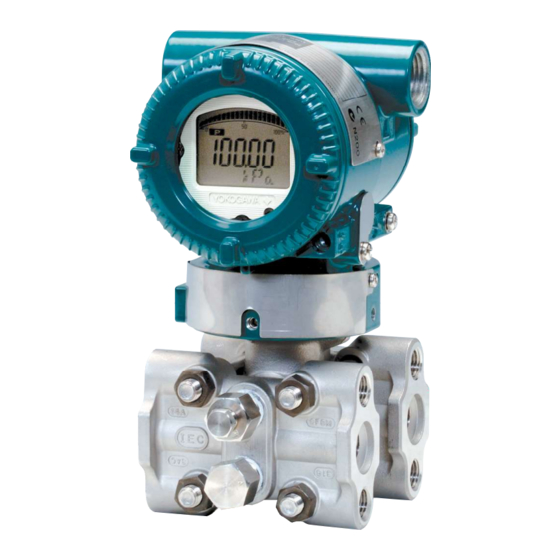
Related Manuals for YOKOGAWA Dpharp EJX510A


Summarization of Contents
Introduction
For Safe Use of Product
Ensures correct and safe use of the instrument by following safety instructions.
Warranty
Details the warranty period, terms, and conditions for product repair and service.
Handling Cautions
Model and Specifications Check
Verifies the model name and specifications on the name plate attached to the case.
Selecting the Installation Location
Provides precautions for selecting an installation location for stable and accurate performance.
Pressure Connection
Highlights precautions for safely operating the transmitter under pressure.
Installation of an Explosion-Protected Instrument
Details precautions for installing intrinsically safe or explosionproof instruments.
Installation
Mounting
Describes how to mount the transmitter on a 50 mm (2-inch) pipe using the mounting bracket.
Mounting the Diaphragm Seals
Provides important instructions for correctly mounting diaphragm seals.
Diaphragm Seals Installation Consideration
Offers considerations for installing diaphragm seals, especially for tank level measurement.
Installing Impulse Piping
Impulse Piping Installation Precautions
General precautions for routing and connecting impulse piping to ensure accurate pressure measurement.
Connecting Impulse Piping to the Transmitter
Details how to connect impulse piping, including checking connections and using manifolds.
Impulse Piping Connection Examples
Illustrates typical impulse piping connections for various fluid types and transmitters.
Process Piping Installation Precautions (EJ 115)
Specific precautions for process piping installation, including flow direction and pipe size.
Wiring
Wiring Precautions
General precautions for wiring, including noise reduction and explosion-protected instrument wiring.
Connections of External Wiring to Terminal Box
Details terminal configuration and wiring for different output types (4-20mA, 1-5V).
Wiring
Provides general wiring guidance and specific connection examples for various transmitter types.
RTD Cable Connection (EJX910A/EJX930A)
Instructions for connecting RTD cables for external temperature measurement.
Grounding
Explains the importance of grounding for transmitter operation and locations of ground terminals.
Power Supply Voltage and Load Resistance
Describes the relationship between power supply voltage and external load resistance for 4-20mA output.
Operation
Preparation for Starting Operation
Steps to confirm transmitter operation and verify/change parameter settings.
Zero Point Adjustment
Procedure for adjusting the transmitter's zero point using a screw or communicator.
Local Parameter Setting
Overview of setting parameters via the integral indicator's push button or external adjustment screw.
Need help?
Do you have a question about the Dpharp EJX510A and is the answer not in the manual?
Questions and answers