Table of Contents
Advertisement
Quick Links
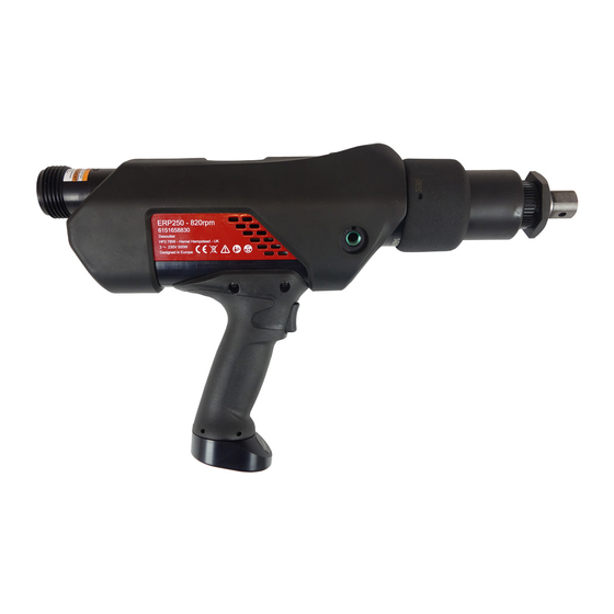
Electric pistol high torque nutrunner
Model
ERP250
ERP500
ERP750
ERP1000
ERP1700
Download the latest version of this document at
www.desouttertools.com/info/6159923510
Read all safety warnings and instructions
Failure to follow the safety warnings and instructions may result in
electric shock, fire and/or serious injury.
Save all warnings and instructions for future reference
Product Instructions
Part number
6151658830
6151658840
6151658850
6151658860
6151658870
WARNING
Printed Matter No. 6159923510
Issue No.
02
Date
10/2019
Page
1 / 20
Advertisement
Table of Contents

Related Manuals for Desoutter Industrial Tools ERP500


Summarization of Contents
Product Information
General Information and Safety
Key instructions, warnings, and definitions of safety signal words for safe operation.
Warranty and Resources
Details on product warranty, website resources, and spare parts information.
Dimensioning
Detailed physical dimensions (A, B, C, D, E, F) for each nutrunner model.
Product Overview
General overview, product description, technical data, and available accessories.
Tool Components and Cables
Details on tool adapters, components, tool cables, and extension cables.
Firmware and Software Requirements
Minimum firmware and software release versions required for system compatibility.
Detailed Technical Specifications
Comprehensive technical specifications including torque ranges, speed, voltage, power, IP rating, weight, and splines.
Suspension Ring Accessory
Details and part number for the suspension ring accessory.
Reaction Bars
Specifications for S-type, Straight, Aluminium L-type, Square, and Sliding Drive reaction bars.
Side Handle
Information and illustration for mounting the side handle accessory.
Installation
Installation Requirements
Guidance on selecting and shaping the torque reaction bar for proper tool function.
Installing the Torque Reaction Bar
Step-by-step instructions for mounting the torque reaction bar onto the tool's gear housing.
Changing Cable Connector Orientation
Procedure for reorienting the tool's cable connector if necessary.
Mounting the Suspension Ring
Instructions for attaching the suspension ring to the tool.
Mounting the Side Handle
Steps for securely attaching the side handle to the tool.
Connecting the Power Cable
Procedure for connecting the power cable to the tool and securing it.
Connecting Tool to Controller
Instructions for safely connecting the tool cable and adapter to the controller.
Operation
Configuration Instructions
Guidelines for setting torque and speed limits for optimal performance.
Starting the Tool
Procedure for fitting sockets, selecting programs, and holding the tool to start operation.
Tightening Reports
Explanation of LED indicators for tightening status (NOK/OK).
Changing Rotation Direction
Instructions on how to select the rotational direction (clockwise, neutral, counterclockwise).
Service
Maintenance Instructions
Guidelines for handling transducerized tools and pre-maintenance safety checks.
Preventive Maintenance
Recommendations for overhaul and preventive maintenance intervals based on usage.
Recommissioning
Checks required before putting the system back into service after maintenance.
Checking Before Service
Verification of main settings and safety devices functionality before re-use.
Need help?
Do you have a question about the Industrial Tools ERP500 and is the answer not in the manual?
Questions and answers