Table of Contents
Advertisement
Model
EABCLRT80-1300
EABCLRT110-1300
EABCLRT80-1300-eLINK
EABCLRT110-1300-eLINK
Download the latest version of this document at
http://www.desouttertools.com/info/6159990990_EN
Read all safety warnings and instructions
Failure to follow the safety warnings and instructions may result in
electric shock, fire and/or serious injury.
Save all warnings and instructions for future reference
E-Pulse Cordless Nutrunner
Product Instructions
Part number
6151663240
6151663250
6151663290
6151663300
WARNING
Printed Matter No. 6159990990_EN
Issue No.
01
Date
04/2024
Page
1 / 32
Advertisement
Table of Contents

Related Manuals for Desoutter EABCLRT80-1300


Summary of Contents for Desoutter EABCLRT80-1300
- Page 1 Printed Matter No. 6159990990_EN Issue No. Date 04/2024 Page 1 / 32 E-Pulse Cordless Nutrunner Product Instructions Model Part number EABCLRT80-1300 6151663240 EABCLRT110-1300 6151663250 EABCLRT80-1300-eLINK 6151663290 EABCLRT110-1300-eLINK 6151663300 Download the latest version of this document at http://www.desouttertools.com/info/6159990990_EN WARNING Read all safety warnings and instructions Failure to follow the safety warnings and instructions may result in electric shock, fire and/or serious injury.
-
Page 2: Table Of Contents
Table of Contents Product Information .......................... 4 General Information......................... 4 Warranty.......................... 4 Website .......................... 4 Information about spare parts .................... 4 Information about spare parts .................... 4 Dimensions .......................... 4 CAD files .......................... 6 Overview ............................ 6 General overview ......................... 6 Product Description...................... 7 Technical Data ........................ 8 Accessories.......................... 8 WI-FI settings ........................ 8 Default tool Ethernet configuration.................. 10 Installation............................ 11 Installation Instructions........................ 11... - Page 3 Advanced tool maintenance with ACCESS KEY................ 26 Motor align ......................... 26 Declaring fixed accessories .................... 26 Upgrading tool firmware ..................... 27 Troubleshooting .......................... 28 What if the tool is locked ....................... 28 List of user infos related to the tools.................... 28 6159990990 / v.01 3 / 32...
-
Page 4: Product Information
• The product warranty relies on the correct use, maintenance, and repair of the tool and its component parts. • Damage to parts that occurs as a result of inadequate maintenance or performed by parties other than Desoutter- Desoutter or their Certified Service Partners during the warranty period is not covered by the warranty. - Page 5 ØB ØC EABALRT80-1300 538 - 21.1 46 - 1.81 58 - 2.28 49 - 1.93 12.7 - 1/2'' EABCLRT80-1300 538 - 21.1 46 - 1.81 58 - 2.28 49 - 1.93 12.7 - 1/2'' EABCLRT80-1300-eLINK 538 - 21.1 46 - 1.81 58 - 2.28...
-
Page 6: Cad Files
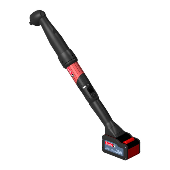
BLRTC tools are e-Pulse wireless pistol nutrunners. They can be equipped with a barcode reader or a tracker. They are hand-held by the operator and powered by a Desoutter battery pack. On delivery, the tool display is protected by a password. -
Page 7: Product Description
Product Information Product Description Output drive Reporting LEDs Trigger Battery Footprint Communication Module Programming Button Reverse Button Programming Button Display Front Light eLINK Module 6159990990 / v.01 7 / 32... -
Page 8: Technical Data
6158119760 Required accessories Battery pack 36 V 2.5 Ah 6158132670 Battery pack charger 6158132700 WI-FI settings Item Desoutter default parameter Other possible values Network name (SSID) Desoutter_1 String of 255 characters Security type WPA/WPA2 PSK Open Shared secret LEAP... - Page 9 Product Information Item Desoutter default parameter Other possible values Radio band 2.4 GHz - Channel 1-11 5 GHz - U-NII-1 5 GHz - U-NII-2 5 GHz - U-NII-2 ext 5 GHz - U-NII-3 Data rate 54 Mbit 1 Mbit 2 Mbit 5.5 Mbit...
-
Page 10: Default Tool Ethernet Configuration
North America Europe Japan Worldwide U-NII-2 U-NII-2 Ext U-NII-3 Default tool Ethernet configuration Item Desoutter default parameter Other possible values Allocation method for IP address Static Keep original IP address DHCP IP address 192.168.5.221 Refer to local settings Subnet mask 255.255.255.0... -
Page 11: Installation
Installation Installation Installation Instructions Inserting the Battery Pack Insert the battery pack (1) in front or behind the tool (2) until a locking sound can be clearly heard. There is no ON/OFF switch: the tool is ready to operate as soon as a battery pack is mounted. When the tool is powered on, tool LEDs are blinking. -
Page 12: How To Install Optional Accessories
Installation How to install optional accessories Refer to the user manual dedicated to the accessory available at https://www.desouttertools.com/resource- centrehttps://www.desouttertools.com/resource-centre. 12 / 32 6159990990 / v.01... -
Page 13: Operation
Operation Operation Configuration Instructions How to configure the tool P 0 0 2 To o l L o c k e d Icons and buttons The password is enabled. The password is disabled. Press the button "Validate/Run reverse". Press the right button. Press the left button. - Page 14 Operation How to disable the passwords On delivery, passwords are enabled (1 by default). Pset and Maintenance passwords are used to protect settings against hazardous changes. A red padlock is displayed on the top line of the main screen. Press this button during 2 seconds. Press this button to reach Configuration.
- Page 15 Operation • Nm • ft.lb • in.lb • kg.m • kg.cm • oz.in • dNm On tool delivery, the torque unit is set to "Nm" by default. Go to CVI CONFIG to change the torque unit. Click this icon to update the product. How to set up the reverse mode On tool delivery, the "Reverse"...
-
Page 16: How To Change Network Parameters
Operation Tick Standalone. Click Write to tool. Click File > Exit to quit. How to set up parameters Plug the eDOCK to the tool and connect it to the USB port of the computer where CVI CONFIG is installed. Launch CVI CONFIG. Go to the tree view area. -
Page 17: Additional Pset Parameters
Operation Change the parameters. Refer to chapters Default tool Ethernet configuration [Page 10] and WI-FI settings. Check that IP address, subnet mask and port number of the controller/hub are compatible. Click this icon to write the new parameters into the tool. Via Easy Pairing When the pairing is done to CONNECT via RFID, WI-FI settings are directly written to the tool. -
Page 18: How To Set Up Psets And Assembly Processes
Operation Tighten your application Final torque ≥ target torque Increase Pulse amplitude by 10% Some pulses appear or are noise perceptible Decrease Rundown speed by 10% Number of pulses Too low Decrease Pulse amplitude by 10% Too high Rundown speed ≥ 100% Increase Rundown speed by 10% Increase Pulse amplitude by 10% Setup OK for the joint... -
Page 19: Operating Instructions
Operation An Assembly Process is commonly called AP and is shown by this icon. The Assembly Process available in products and systems consists in executing a Pset a certain number of times or unlimited. This feature is named Batch. Create as many Psets / Assembly Processes as you want. For each of them, enter a description which will be displayed on the tool screen. - Page 20 Operation Hold the tool by means of the handle and apply to the fastener to be tightened. WARNING Risk Of Injury As the reaction force increases in proportion to the tightening torque, there is a risk of severe bodily injury of the operator as a result of unexpected behavior of the tool.
- Page 21 Operation Batch count Ellipse The ellipse represents the batches. In this example, 3 tightenings out of 4 are completed. How to interact on the Assembly Process Press the left button to abort the Assembly Process. The following actions are protected by the "Maintenance" password. To have them available, enter the Maintenance password in the "Configuration"...
- Page 22 Operation The tool powers off after 30 minutes of inactivity. Long press the reverse button. Refer to "Power off" configurable on tool display or with CVI CONFIG. Unplug and plug the battery pack. 22 / 32 6159990990 / v.01...
-
Page 23: Service
Service Service Tool information from tool display Go to "Maintenance/Tool" menu to get the following information: Total counter Number of tightenings since the manufacturing of the tool. Battery The current voltage value is displayed. The "Low battery" message is displayed when lower than 32 At 31 V, the tool stops. -
Page 24: Read Before Maintenance
Service Read before maintenance WARNING Connection Hazard The tool can start unexpectedly and cause severe bodily injury. Prior to any maintenance task, disconnect the tool. ► Maintenance should be performed by qualified personnel only. Follow standard engineering practices and refer to exploded views for disassembling and reassembling the different parts of the system. -
Page 25: Calibration Via Tool Display
This function is set in the "Maintenance" menu. Enter the Maintenance password in the "Configuration" menu. Insert a torque transducer in line with the tool and connect it to any measuring unit from the Desoutter range. Go to "Maintenance/Calibration". Select the number of tightenings required to execute the calibration and press OK. -
Page 26: Calibration With Edock And Cvimonitor
Advanced tool maintenance with ACCESS KEY Launch CVIMONITOR. To activate the screens, you need to have an ACCESS KEY USB stick with the right profile (configured with the Desoutter CVIKEY software). If not, contact your CVIKEY manager for support. Motor align Click this icon. -
Page 27: Upgrading Tool Firmware
It is mandatory to calibrate the tool equipped with the fixed accessory before use. Upgrading tool firmware Click this icon. Click Upgrade tool firmware. Contact your Desoutter representative to get the last firmware version. Follow the instructions on screen. 6159990990 / v.01 27 / 32... -
Page 28: Troubleshooting
Try first to wake up the tool. LEDs are turned on. The tool is not able Replace the battery pack. to start. Contact your Desoutter representative to get more information and support. List of user infos related to the tools Type Colour... - Page 29 2- Check the tool cable is not damaged. W212 Result not stored 1- It is not possible to store the tightening result in the system. 2- Contact your Desoutter representative for support. W216 Current high 1- Maximum current exceeded. 2- Contact your Desoutter representative for support.
- Page 30 2- Replace the battery pack or your configuration. E223 Drive init error 1- Software failure. 2- Restart the system. 3- If the problem occurs again, contact your Desoutter representative for support. E227 Motor stalled 1- Motor stalled (could be missing phase, wrong motor tune or power electronics failure) 2- Try once again.
- Page 32 Original instructions Founded in 1914 and headquartered in France, Desoutter Industrial Tools is a global leader in electric and pneumatic assembly tools serving a wide range of assembly and manufacturing operations, including Aerospace, Automotive, Light and Heavy Vehicles, Off-Road, General Industry.
Need help?
Do you have a question about the EABCLRT80-1300 and is the answer not in the manual?
Questions and answers