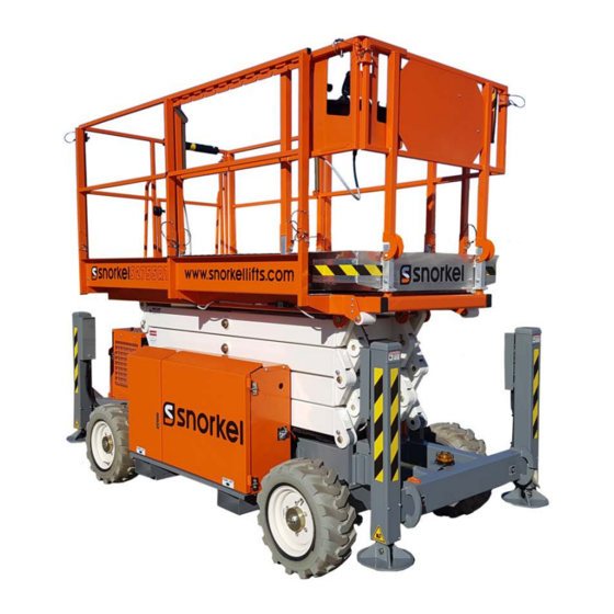
Summarization of Contents
General Information
Machine Classification
Details the machine's classification and AS1418.1 Group Classification.
Commissioning Information
Information regarding the Pre Delivery and Inspection Report (PDIR) process.
General Specifications
S2255RTE Specifications
Technical specifications for the S2255RTE model, including dimensions and capabilities.
S2755RT Specifications
Technical specifications for the S2755RT model, including dimensions and capabilities.
Maintenance Information
Manual Overview and Organization
Overview of the manual's scope, limitations, and section organization.
Maintenance Schedules and Procedures
Details daily, 90-day/150-hour, and yearly/500-hour preventive maintenance schedules and procedures.
Specific Maintenance Topics
Covers lubricants, hydraulic oil, filters, batteries, and interlock tests.
Scissor Interlock System Tests
Tests to ensure the stabilizer/axle/scissor interlock system functions correctly.
Repair Parts
Base Assemblies
Diagrams and parts for S2255RT and S2755RT Base Assemblies.
Axle and Swing Arm Assemblies
Diagrams and parts for Steer Axle and Swing Arm Assemblies.
Cabinet Assemblies
Diagrams and parts for Control, Serial Plate, Control Box, Motor, Power, and Cabinet Mounting Assemblies.
Stabiliser and Wheel Assemblies
Diagrams and parts for Stabiliser Leg and Wheel Mounting Assemblies.
Platform and Stack Assemblies
Diagrams and parts for Base, Stack, Platform, and Rear Handrail Assemblies.
Scissor Stack Assemblies
Diagrams and parts for S2255RT and S2755RT Scissor Stacks.
Hydraulic Tank and Decal Assemblies
Diagrams and parts for Hydraulic Oil Tanks and Placards/Decals.
Hydraulics
Hose Identification and Schematics
Hose part numbers, colour codes, and the main hydraulic schematic.
Manifold Assemblies
Diagrams and parts for Main, 4WD, and Auto Stabiliser Manifolds.
Cylinder Assemblies
Diagrams and parts for Steer, Axle, Lift, and Stabiliser Leg Cylinders.
Electrical
GP400 Control System
Details GP400 menus, diagnostics, adjustments, setups, and I/O allocations.
Control Box Assemblies
Diagrams and parts for Upper and Lower Control Boxes.
Wiring Diagrams
Wiring diagrams for control boxes, hydraulic compartment, sensors, and stabiliser legs.
Options
240V Power Options
Diagrams and parts for 240V Base and Platform Assembly options.
Ordering and Support Information
Ordering Parts and Manuals
Procedures for ordering parts and obtaining manuals.
Responsibilities and Warranty
Owner responsibilities and product warranty terms.


Need help?
Do you have a question about the S2755RTE and is the answer not in the manual?
Questions and answers