Table of Contents
Advertisement
Quick Links
Advertisement
Chapters
Table of Contents
Troubleshooting

Related Manuals for Snorkel SL26-01 Series


Summary of Contents for Snorkel SL26-01 Series
- Page 1 SL26SL SL30SL PARTS MANUAL...
-
Page 2: Table Of Contents
GENERAL INFORMATION INTRODUCTION OPERATIONS & SPECIFICATIONS TROUBLESHOOTING REPAIR PARTS GENERAL ASSEMBLY SL30SL GENERAL ASSEMBLY SL26SL HYDRAULIC HOSE ASSEMBLY HYDRAULIC HOSE ASSEMBLY HYDRAULIC HOSE ASSEMBLY CHASSIS ASSY SL26/30SL LOWER CONTROL PANEL ASSEMBLY - CE STEER, AXLE FLOAT & TILT CYLINDER CONTROL MODULE ASSEMBLY ENGINE ASSEMBLY - KUBOTA D902 2-10 ENGINE CABINET ASSEMBLY... - Page 3 TOW HITCH BLOCKHEATER...
- Page 4 PARTS & SERVICES MANUAL Part Number 516123-200E Serial Number SL26RTE and after OCT 2019 Serial Number SL30RTE and after...
- Page 6 SL26/30ERT SERVICE AND PARTS MANUAL FOREWORD This manual is divided into six sections namely; SECTION 1: INTRODUCTION General description and machine specifications. SECTION 2: OPERATION AND SPECIFICATION See seperate Operators Manual. SECTION 3: SERVICE AND REPAIR Preventative maintenance and service information. SECTION 4: TROUBLESHOOTING Causes and solutions to typical problems.
- Page 7 Please understand that these warnings cannot cover all conceivable ways in which service, whether or not recommended by Snorkel, might be carried out, or of the possible hazardous consequences of each conceivable way, nor could snorkel investigate all such ways.
- Page 8 INTRODUCTION PURPOSE The purpose of this service and parts manual is to provide instructions and illustrations for the operation and maintenance of this work platform manufactured by Snorkel. SCOPE The manual includes procedures for proper operation, maintenance, adjustment and repair of this product as well as recommended maintenance schedules and troubleshooting.
- Page 9 INTRODUCTION PLATFORM CONTROLLER The platform controller contains the controls to operate the machine. It is located at the front of the platform. A complete explanations of control functions can be found in section 2. ELEVATING ASSEMBLY The platform is raised and lowered by the elevating assembly. The hydraulic pump driven by the engine, powers the cylinders.
- Page 10 SL26/30SL Series ENGLISH When contacting Snorkel for service or parts information, be sure to include the model and serial numbers from the equipment name plate. Should the name plate be missing, the serial number is also stamped on top of the chassis above the front axle pivot...
- Page 11 WARNING All personnel shall carefully read, understand and follow all safety rules and operating instructions before operating or performing maintenance on any SNORKEL aerial work platform. E L E C T R O C U T I O N TIP OVER HAZARD COLLISION HAZARD...
- Page 12 Harness attachment points are provided in the platform and the manufacturer recommends the usage of a fall restraint harness, especially where required by national safety regulations. All harness attachment points on SNORKEL vehicles have been tested with a force of 3,650 lbs (16.3 KN) per person.
- Page 13 SAFETY NOTICE NOTE 1. To bypass any safety equipment is prohibited and presents a danger for the person/persons on the aerial work platform and in its working range. 2. Modification to the aerial work platform is prohibited or permissible only at the approval of Snor- kel.
- Page 14 CONTENTS INTRODUCTION GENERAL DESCRIPTION SPECIAL LIMITATIONS SPECIAL LIMITATIONS PLATFORM CAPACITY MANUAL FORCE BEAUFORT SCALE LIFT OVERLOAD ALARM CONTROLS/PRE-OPERATION PLATFORM CONTROLS AND INDICATORS CHASSIS CONTROLS AND INDICATORS PRE-OPERATION SAFETY INSPECTION 2-10 SYSTEM FUNCTION INSPECTION 2-11 OPERATION 2-12 STARTING THE MACHINE 2-12 STEERING 2-12 ELEVATING THE PLATFORM...
-
Page 15: Introduction
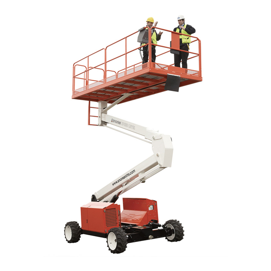
INTRODUCTION INTRODUCTION This manual covers the operation of the SL26/30 Speed level series Self-Propelled Work Platforms. This manual must be stored on the machine at all times. GENERAL DESCRIPTION 1. Platform 2. Elevating Assembly 3. Chassis 4. Power Module 5. Control Module 6. -
Page 16: Special Limitations
SPECIAL LIMITATIONS SPECIAL LIMITATIONS Travel with platform raised is limited to a maximum speed of 0.8 km/h (0.5 mph). Elevating the work platform is limited to firm surfaces only. D A N G E R The elevating function shall ONLY be used when the work platform is levelled and on a rm surface. The work platform is designed to be driven over uneven, rough or soft terrain however, great care is required when traversing adverse terrain. -
Page 17: Lift Overload Alarm
SPECIAL LIMITATIONS LIFT OVERLOAD ALARM If a load equivalent to 100% of safe working load is lifted, the overload LED’s on the platform and ground control box will illuminate. However, If a load which is greater than the safe working load is placed on the platform, all machine functions will cease to operate and a warning alarm will sound. -
Page 18: Controls/Pre-Operation
CONTROLS/PRE-OPERATION PLATFORM CONTROLS AND INDICATORS 1. Emergency stop button 2. Horn button 3. OFF/ON Engine start switch 4. Glow plug button 5. Engine warning LED 6. Low speed drive switch 7. Low speed drive enabled LED 8. Medium speed drive switch 9. -
Page 19: Pre-Operation Safety Inspection
CONTROLS/PRE-OPERATION PRE-OPERATION SAFETY INSPECTION NOTE: Carefully read, understand and follow all safety rules, operating instructions, labels and National Safety Instructions/Requirements. Perform the following steps each day before use. 1. Open modules and inspect for damage, fluid leaks or missing parts. Check the level of the hydraulic fluid with the platform fully lowered. -
Page 20: System Function Inspection
SYSTEM FUNCTION INSPECTION Refer to figure 2-3 and 2-4 on page 2-9 for the locations of various controls and indicators. W A R N I N G Stand clear of the work platform while performing the following checks: - Prior to operating the work platform, survey the work area for surface hazards such as holes, drop-o s, bumps and debris. -
Page 21: Operation
OPERATION Before operating the work platform, ensure that the pre-operation safety inspection has been com- pleted and that any deficiencies have been corrected. Never operate a damaged or malfunction- ing machine. The operator must be thoroughly trained on this machine. STARTING THE MACHINE 1. -
Page 22: Travel With The Platform Elevated
OPERATION TRAVEL WITH THE PLATFORM ELEVATED NOTE: The machine will travel at reduced speed when the platform is elevated. 1. Check that the route is clear of obstacles (persons, obstructions, holes, drop-offs, bumps and debris) and capable of supporting the wheel load. 2. -
Page 23: Platform Extension (Sl26 Speed Level Only)
OPERATION PLATFORM EXTENSION (SL26 SPEED LEVEL ONLY) The platform can be extended and securely locked into position. Use the following procedure to extend the platform: 1. Enter the platform and close the gate. C A U T I O N The extension platform is free to move when the handles are unlocked. -
Page 24: Unfold Procedure
OPERATION 4. Close the latch gate. 5. Remove nuts, bolts and washers from the top of the rear guardrail. Fold the rear guardrail down onto the platform being careful to keep latched at all times. 6. Remove nuts, bolts and washers from the top of the side guardrails. Lift up and fold one side guardrail in resting it on the deck. -
Page 25: Emergency Procedure
EMERGENCY PROCEDURE TOWING OR WINCHING Perform the following action only when the machine will not operate under its own power and it is necessary to move the machine or when winching onto a transport vehicle (Refer to “Transporting the work platform” on page 2-18). C A U T I O N DO NOT tow or winch the machine faster than 0.3 m/s (1 ft/s). -
Page 26: Emergency Lowering
EMERGENCY PROCEDURE W A R N I N G Never tow faster than 0.3 m/s (1 ft/s). Never operate the work platform with the parking brakes released. Serious injury or damage could result. EMERGENCY LOWERING W A R N I N G If the platform should fail to lower, NEVER climb down the elevating assembly. -
Page 27: Transportation
TRANSPORTATION PREPARATION FOR SHIPMENT 1. Fully lower the platform. 2. Turn batteries OFF with master switch. LIFTING BY CRANE 1. Secure straps to chassis tie down/lifting lugs only. 2. Place the platform onto the transport vehicle in transport position. 3. Chock the wheels. 4. -
Page 28: Maintenance
Battery uid is highly corrosive. Thoroughly rinse away any spilled uid with clean water. Always replace batteries with Snorkel batteries or manufacturer approved replacements. Check the battery fluid level daily, especially if the work platform is being used in a warm, dry •... -
Page 29: Inspection And Maintenance
INSPECTION AND MAINTENANCE The complete inspection consists of periodic visual and operational checks along with periodic mi- nor adjustments that assure proper performance. Daily inspection will prevent abnormal wear and prolong the life of all systems. The inspection and maintenance schedule should be performed by personnel who are trained and familiar with mechanical and electrical procedures. -
Page 30: Daily Preventative Maintenance Schedule
INSPECTION AND MAINTENANCE DAILY PREVENTATIVE MAINTENANCE SCHEDULE MAINTENANCE TABLE KEY PREVENTATIVE MAINTENANCE REPORT Y = Yes/Acceptable Date: ______________________________ N = No/Not Acceptable Owner: _____________________________ R = Repaired/Acceptable Model #: ____________________________ Serial #: ____________________________ Serviced by: _________________________ COMPONENT INSPECTION OR SERVICES COMPONENT INSPECTION OR SERVICES Operator’s... -
Page 31: Specifications
SPECIFICATIONS ITEM SL26SL SL30SL PLATFORM SIZE (INSIDE TOEBOARDS) STANDARD 1.71 m x 3.66 m [67.5 in. x 144 in.] 1.71 m x 4.22 m [67.5 in. x 166.5 in.] SLIDE OUT DECK EXTENDED 1.71 m x 4.55 m [67.5 in. x 179 in.] MAXIMUM PLATFORM CAPACITY STANDARD 680 kg [1500 lbs.]... - Page 32 SPECIFICATIONS WHEEL LOADING 2000 kg (4400 lb) 2000 kg (4400 lb) VIBRATION OF THIS MACHINE DOES NOT 2.5 m/s 2.5 m/s EXCEED NOISE PRESSURE LEVEL 107 dB AT CONTROL STATION 107 dB AT CONTROL STATION MACHINE VIBRATION WHOLE BODY VIBRATION < 0.5 m/s , HAND WHOLE BODY VIBRATION <...
-
Page 33: Waste Removal And Disposal
WASTE DISPOSAL AND REMOVAL Page 2 - 24 SL26/30SL... - Page 34 TROUBLESHOOTING CONTENTS INTRODUCTION GENERAL PROCEDURE TROUBLESHOOTING PROCEDURE SPECIAL TOOLS ADJUSTMENT PROCEDURES CHECKING PUMP PRESSURES TROUBLESHOOTING GUIDE DIAGNOSTICS SYSTEM PLATFORM GROUND INPUTS ANALOGS OUTPUTS SL26-30 I/O LIST GP400 I/O PLATFORM MATRIX I/O SL26/30SL Page 4 - 1...
-
Page 35: Introduction
Careful inspection and accurate analysis of the symptoms listed in the troubleshooting guide will localize the trouble more quickly than any other method. This manual cannot cover all possible problems that may occur. If a specific problem is not covered in this manual, call Snorkel for service assistance. -
Page 36: Adjustment Procedures
TROUBLESHOOTING ADJUSTMENT PROCEDURES Hydraulic settings must be checked whenever a component is repaired or replaced. • Do not remove the counterbalance valves and “bench test” them if they are faulty. • Only replace them with valves of the same type. •... -
Page 37: Diagnostics
TROUBLESHOOTING DIAGNOSTICS The EZcal display has a number of diagnostic tools to aid troubleshooting. To access these with the machine switched on, press and hold “ESC” for 5 seconds until “#### MENU: HELP: PRESS EN- TER” is displayed. Press “ENTER” for a top level fault message. For more detailed diagnostics from the top menu, scroll right to “DIAGNOSTICS”... -
Page 38: Sl26-30 I/O List
TROUBLESHOOTING SL26-30 I/O LIST GP400 I/O Meaning Movement Manifold Block Drive manifold Block Elevated drive is always low speed Connector-pin I/O type Function CE Function ANSI Comment P7-1 TBM positive TBM positive Powers valve outputs, does not power GP400 P8-14 TBM negative TBM negative P7-2... - Page 39 TROUBLESHOOTING GP400 I/O Connector-pin I/O type Function CE Function ANSI Comment P4-7 High side 2 A Throttle relay Throttle relay Energise for high revs output P4-1 High side PWM Proportional valve Proportional valve - Analogue output to propor- output - MM:SP1 MM:SP1 tional valve P4-8...
-
Page 40: Platform Matrix I/O
TROUBLESHOOTING GP400 I/O Connector-pin I/O type Function CE Function ANSI Comment P5-1 High side 2 A High speed sol - High speed sol - Energised for high speed drive output DM:SV13 DM:SV13 Axle float solenoid Axle float solenoid P4-15 High side 2 A Energise when driving and output NOT elevated to allow axle... - Page 41 TROUBLESHOOTING PLATFORM MATRIX I/O Connector-pin I/O type Function CE Function ANSI Comment MP4-6 Low side 1 A output Tilt LED Tilt LED Flash when platform is tilted beyond platform tilt limits. MP4-7 Low side 1 A output Engine LED Engine LED Steady on when GP400 P7- 13,14, or 15 are low.
-
Page 42: General Assembly Sl30Sl
SL26SL SL30SL PARTS MANUAL GENERAL ASSEMBLY SL30SL REPAIR PARTS GENERAL ASSEMBLY SL30SL Tue Feb 16 03:29:13 UTC 2021... - Page 43 SL26SL SL30SL PARTS MANUAL GENERAL ASSEMBLY SL30SL アイテム 部品番号 名前 数量 505600-000 GENERAL ASSEMBLY SL30SL Shown 505603-000 PLATFORM ASSEMBLY SL26RTE 505501-000 CHASSIS ASSY SL26/30RTE 505602-000 ELEVATING ASSEMBLY SL26RTE 1 505504-000 Power module 505515-000 Control module GENERAL ASSEMBLY SL30SL Tue Feb 16 03:29:13 UTC 2021...
-
Page 44: General Assembly Sl26Sl
SL26SL SL30SL PARTS MANUAL GENERAL ASSEMBLY SL26SL REPAIR PARTS GENERAL ASSEMBLY SL26SL Tue Feb 16 03:29:13 UTC 2021... -
Page 45: Platform Assembly - Sl30Sl
SL26SL SL30SL PARTS MANUAL GENERAL ASSEMBLY SL26SL アイテム 部品番号 名前 数量 505500-000 GENERAL ASSEMBLY SL26SL Shown 505503-000 PLATFORM ASSEMBLY - SL30SL 505501-000 CHASSIS ASSY SL26/30RTE 505502-000 ELEVATING ASSY SL30SL 505504-000 Power module 505515-000 Control module GENERAL ASSEMBLY SL26SL Tue Feb 16 03:29:13 UTC 2021... - Page 46 SL26SL SL30SL PARTS MANUAL HYDRAULIC HOSE ASSEMBLY REPAIR PARTS HYDRAULIC HOSE ASSEMBLY Tue Feb 16 03:29:14 UTC 2021...
- Page 47 SL26SL SL30SL PARTS MANUAL HYDRAULIC HOSE ASSEMBLY アイテム 部品番号 名前 数量 510379-000 HYDRAULIC HOSE ASSEMBLY Shown (BEFORE SN 01-060213) 510380-000 LHF motor drain to BH 510381-000 LHF BH to return manifold 510382-000 RHF motor drain to BH 510383-000 RHF BH to return manifold 510384-000 LHR motor drain to BH 510385-000 LHR BH to return manifold 510386-000 RHR motor drain to BH 510387-000 RHR BH to return manifold 510388-000 Lift cylinder to return manifold 510389-000 Brake port to LHR BH TEE 510390-000 LHR BH to LH brake 510391-000 LHR BH TEE to RHR BH 510392-000 RHR BH to RH brake 510393-000 Movement manifold to tilt...
- Page 48 SL26SL SL30SL PARTS MANUAL HYDRAULIC HOSE ASSEMBLY アイテム 部品番号 名前 数量 510406-000 Drive manifold MFFR to BH 510407-000 Drive manifold MRFR to BH 510408-000 Drive manifold MFRL to BH 510409-000 Drive manifold MRRL to BH 510410-000 BH to RL motor 510411-000 Drive manifold MFRR to BH 510412-000 Drive manifold MRRR to BH 510413-000 BH to RR motor 510414-000 Movement to drive manifold press 510415-000 Movement to drive manifold return 510416-000 BH to RHF motor 510417-000 BH to LHF motor 510418-000 Return filter to tank 510419-000 Tank to pump suction 510826-000 Lift TEE to axle float cylinder...
- Page 49 SL26SL SL30SL PARTS MANUAL HYDRAULIC HOSE ASSEMBLY REPAIR PARTS HYDRAULIC HOSE ASSEMBLY Tue Feb 16 03:29:14 UTC 2021...
- Page 50 SL26SL SL30SL PARTS MANUAL HYDRAULIC HOSE ASSEMBLY アイテム 部品番号 名前 数量 514942-000 HYDRAULIC HOSE ASSEMBLY Shown (After SN 01-060214) 510380-000 LHF motor drain to BH 510381-000 LHF BH to return manifold 510382-000 RHF motor drain to BH 510383-000 RHF BH to return manifold 510384-000 LHR motor drain to BH 510385-000 LHR BH to return manifold 510386-000 RHR motor drain to BH 510387-000 RHR BH to return manifold 510388-000 Lift cylinder to return manifold 510389-000 Brake port to LHR BH TEE 510390-000 LHR BH to LH brake 510391-000 LHR BH TEE to RHR BH 510392-000 RHR BH to RH brake 510393-000 Movement manifold to tilt...
-
Page 51: Hydraulic Hose Assembly
SL26SL SL30SL PARTS MANUAL HYDRAULIC HOSE ASSEMBLY HYDRAULIC HOSE ASSEMBLY Tue Feb 16 03:29:14 UTC 2021... - Page 52 SL26SL SL30SL PARTS MANUAL HYDRAULIC HOSE ASSEMBLY アイテム 部品番号 名前 数量 510406-000 Drive manifold MFFR to BH 510407-000 Drive manifold MRFR to BH 510408-000 Drive manifold MFRL to BH 510409-000 Drive manifold MRRL to BH 510410-000 BH to RL motor 510411-000 Drive manifold MFRR to BH 510412-000 Drive manifold MRRR to BH 510413-000 BH to RR motor 510414-000 Movement to drive manifold press 510415-000 Movement to drive manifold return 510416-000 BH to RHF motor 510417-000 BH to LHF motor 510418-000 Return filter to tank 510419-000 Tank to pump suction 510826-000 Lift TEE to axle float cylinder...
- Page 53 SL26SL SL30SL PARTS MANUAL HYDRAULIC HOSE ASSEMBLY REPAIR PARTS HYDRAULIC HOSE ASSEMBLY Tue Feb 16 03:29:15 UTC 2021...
- Page 54 SL26SL SL30SL PARTS MANUAL HYDRAULIC HOSE ASSEMBLY アイテム 部品番号 名前 数量 515419-000 HYDRAULIC HOSE ASSEMBLY Shown (AFTER SN SL26SL-01- xxxx00073, SL30SL-01- xxxx00158) 515428-000 LHF motor drain to return manifold 515421-000 RHF motor drain to return manifold 515429-000 LHR motor drain to return manifold 515435-000 RHR motor drain to return manifold 510388-000 Lift cylinder to return manifold 515430-000 Brake port to manifold 515453-000 LHR BH to LH brake 515436-000 manifold to RHR brake 510393-000 Movement manifold to tilt cylinder -Left 515424-000 Steer cylinder to manifold 515425-000...
- Page 55 SL26SL SL30SL PARTS MANUAL HYDRAULIC HOSE ASSEMBLY アイテム 部品番号 名前 数量 515433-000 Drive manifold MFRL to RL MOTOR 515434-000 Drive manifold MRRR to RR MOTOR 515431-000 Drive manifold MFRR to RR MOTOR 515434-000 Drive manifold MRRR to RR MOTOR 510414-000 Movement to drive manifold press 510415-000 Movement to drive manifold return 510418-000 Return filter to tank 510419-000 Tank to pump suction 510826-000 Lift TEE to axle float cylinder HYDRAULIC HOSE ASSEMBLY Tue Feb 16 03:29:15 UTC 2021...
- Page 56 SL26SL SL30SL PARTS MANUAL CHASSIS ASSY SL26/30SL REPAIR PARTS CHASSIS ASSY SL26/30SL Tue Feb 16 03:29:15 UTC 2021...
- Page 57 SL26SL SL30SL PARTS MANUAL CHASSIS ASSY SL26/30SL アイテム 部品番号 名前 数量 505501-000 CHASSIS ASSY SL26/30RTE Shown 064320-001 1st post weldment (Before SL30- 01-00168 / SL26-01-00066) 513347-000 1st post weldment (After SL30- 01-00177+ inc.00169,00173 / SL26-01-00090+ inc. 00067,00074,00073) 064331-001 Leveller weldment (Before SL30- 01-00168 / SL26-01-00066) 513392-000 Leveller weldment (After SL30- 01-00177+ inc.00169,00173 / SL26-01-00090+ inc. 00067,00074,00073) 510501-000 Weldment, chassis 510497-000 Weldment, front axle 064343-001 Trunnion 011256-014 Screw, trunnion 011238-008 Washer 064383-000 Thrust washer, 5 mm 064383-001...
- Page 58 SL26SL SL30SL PARTS MANUAL CHASSIS ASSY SL26/30SL アイテム 部品番号 名前 数量 069129-001 Wheel, left hand (Marking) 069129-011 Wheel, left hand (Non- Marking),Before SN SL26-01- 00044, SL30-01-00112 515377-001 Wheel, left hand (Non- Marking),After SN SL26-01- 00045, SL30-01-00113 069129-003 Wheel, left hand ANSI 062642-001 Bushing, motor mount 505201-000 Drive motor, rear 011257-014 Bolt, drive motor, rear 063905-101 Steer cylinder 512318-000 Bushing, axle/Motor mount 510333-000 Steering link arm 505564-000 Motor mount 505202-000 Drive motor, front 064812-000 Hub, front 027931-057 Bushing, roller (Before SN...
- Page 59 SL26SL SL30SL PARTS MANUAL CHASSIS ASSY SL26/30SL アイテム 部品番号 名前 数量 064345-100 Tilt cylinder 509445-000 Bearing spacer 064349-000 Bearing spacer 505046-000 Nut, steering linkage 057052-130 Bolt, front motor mount 056069-012 WASHER DIN125A M12 ZP 011238-005 Washer, rear motor 056064-012 NUT HEX M12 X 1.75 GR 10.9 SELF LOCKING DIN 985 064347-000 Level cover plate 064384-000 Channel 509462-000 Bottom axle pin 011782-001 Bearing thrust washer 064294-004 Actuator lever 15-0489 Location pad 503995-000 Bracket, proximity switch 509535-000...
- Page 60 SL26SL SL30SL PARTS MANUAL LOWER CONTROL PANEL ASSEMBLY - CE REPAIR PARTS LOWER CONTROL PANEL ASSEMBLY - CE Tue Feb 16 03:29:15 UTC 2021...
- Page 61 SL26SL SL30SL PARTS MANUAL LOWER CONTROL PANEL ASSEMBLY - CE アイテム 部品番号 名前 数量 514487-000 LOWER CONTROL PANEL Shown ASSEMBLY - CE 514488-000 LCB weldment 510521-000 GROUND OP SWITCH (ENABLE) 510522-000 TOGGLE SWITCH (RAISE/LOWER) 514132-000 BOOT 510542-000 PUSHBUTTON BLACK C/W 1 N/O CON 3087803 EZCal Panel - Trionics 512543-000 3 POS'N KEY SWITCH - STAYPUT 1 510524-000 PUSH/PULL SW ASSY W/NC CONTACT 514496-000 LCB front panel 505082-014 Button HD screw M5 x 14 LG 512366-000...
- Page 62 SL26SL SL30SL PARTS MANUAL LOWER CONTROL PANEL ASSEMBLY - CE アイテム 部品番号 名前 数量 509755-000 Mate-N-lock socket contact 509741-000 FUSE HOLDER 509740-002 10 AMP blade fuse 100338-013 CRIMP PIN DEUTSCH 501251-016 SBHCS M4 x .7 x 16 GR 10.9 black finish 056069-004 Wshr, SteelFlatWshr M4 DIN125 056066-004 NUT NYLOCK DIN985 M4 8.0 ZP 4 LOWER CONTROL PANEL ASSEMBLY - CE Tue Feb 16 03:29:15 UTC 2021...
- Page 63 SL26SL SL30SL PARTS MANUAL STEER, AXLE FLOAT & TILT CYLINDER REPAIR PARTS STEER, AXLE FLOAT & TILT CYLINDER Tue Feb 16 03:29:15 UTC 2021...
- Page 64 SL26SL SL30SL PARTS MANUAL STEER, AXLE FLOAT & TILT CYLINDER アイテム 部品番号 名前 数量 063905-010 Seal kit - steer cylinder 064345-010 Seal kit - tilt cylinder 064346-010 Seal kit - axle float cylinder 063905-101 Steer cylinder 064345-100 Tilt cylinder 064346-100 Axle float cylinder STEER, AXLE FLOAT & TILT CYLINDER Tue Feb 16 03:29:15 UTC 2021...
-
Page 65: Control Module Assembly
SL26SL SL30SL PARTS MANUAL CONTROL MODULE ASSEMBLY REPAIR PARTS CONTROL MODULE ASSEMBLY Tue Feb 16 03:29:15 UTC 2021... -
Page 66: Lower Control Panel Assembly - Ansi
SL26SL SL30SL PARTS MANUAL CONTROL MODULE ASSEMBLY アイテム 部品番号 名前 数量 505505-000 CONTROL MODULE ASSEMBLY Shown 302-0049 Switch Battery Disconnect 514487-000 LOWER CONTROL PANEL ASSEMBLY - CE 514487-001 LOWER CONTROL PANEL Shown ASSEMBLY - ANSI 510505-000 Cover, hydraulic hoses 5563048 FLAT WASHER M 5 510588-006 WSHR FLAT M6 510588-008 M8, plain washer 510588-010 M10, plain washer 510593-012 Pan head screw, M5 x 12 mm 13-2367 Manifold tank line drain 510567-025 CSK socket head screw, M6 x 25 058490-025 Bolt, M5 x 25 mm 058491-016 BOLT HEXSETSCREW DIN933... - Page 67 SL26SL SL30SL PARTS MANUAL CONTROL MODULE ASSEMBLY アイテム 部品番号 名前 数量 3618-32 Hose Clamp 34-37mm 12716-13 Top Plate 515293-000 Cabinet Support 8342416 Latch, Adjustable Trigger, Key 508CH 3040269 Boot Cable Entry Black I/O GA 300840 Lock Out Lever Assembly 502197-000 M8 x 300 hook bolt 064040-000 Angle battery hold down 11470 LEFT HAND HINGE WELDMENT, UPPER 11470-1 RIGHT HAND HINGE WELDMENT, UPPER 11558 Hydraulic Tank Assembly 062299-002 BATTERY 12vdc 11679 Cabinet Door - Small 11680 Cabinet Door - Large 514721-000...
- Page 68 SL26SL SL30SL PARTS MANUAL CONTROL MODULE ASSEMBLY アイテム 部品番号 名前 数量 515611-000 BEACON ASSY AMBER CONTROL MODULE ASSEMBLY Tue Feb 16 03:29:15 UTC 2021...
- Page 69 SL26SL SL30SL PARTS MANUAL ENGINE ASSEMBLY - KUBOTA D902 REPAIR PARTS ENGINE ASSEMBLY - KUBOTA D902 Tue Feb 16 03:29:16 UTC 2021 2-10...
- Page 70 SL26SL SL30SL PARTS MANUAL ENGINE ASSEMBLY - KUBOTA D902 アイテム 部品番号 名前 数量 14004 Kubota D902 Engine Shown 304-0174 Solenoid 3602-08 Metric Hex Nut 3603-06 Plain Washer 3603-08 Plain Washer 3603-10 Plain Washer 3605-08 Spring Washer 056021-008 Washer SpringWasher DIN127B 3610-06020 Metric Bolt 3610-08020 Metric Bolt 3610-08030 Metric Bolt 3610-08040 Metric Bolt 3610-10025 Metric Bolt 3611-06 Metric Nyloc Nut 3611-08...
- Page 71 SL26SL SL30SL PARTS MANUAL ENGINE ASSEMBLY - KUBOTA D902 アイテム 部品番号 名前 数量 13905 Saddle Clamp 60017-007 1" x 3/8 UNC Bolt 60017-010 1" x 3/8 UNC Bolt 60021-008 1/4" NF Hex Nut 60030-049 3/8" Plain Washer 512968-000 Hyd Fitting - Straight ORFS(16) - SAE(16) 512969-000 Hyd Fitting - Straight ORFS(08) - SAE(10) 2650001 Swivel Inline 2690004 Rod End 7630208 Engine Mount 13987 Coupling - KEA bell housing kit 515952-000 FAN,SUCTION (not illustrated) 516251-000 Gasket, Exhaust Side 516251-001 Gasket,Cylinder Head Side(Not...
-
Page 72: Engine Cabinet Assembly
SL26SL SL30SL PARTS MANUAL ENGINE CABINET ASSEMBLY REPAIR PARTS ENGINE CABINET ASSEMBLY Tue Feb 16 03:29:16 UTC 2021 2-11... - Page 73 SL26SL SL30SL PARTS MANUAL ENGINE CABINET ASSEMBLY アイテム 部品番号 名前 数量 SL26/30SL - Kubota D902 ENGINE CABINET ASSEMBLY Shown 1650-010 Relay 12V 514612-000 Plugin relay base 3602-06 Metric Hex Nut 3603-04 Plain Washer 3603-05 Plain Washer 3603-06 Plain Washer 3603-08 Plain Washer 3603-10 Plain Washer 3604-04035 Pan Head Screw 3604-05012 Pan Head Screw 3605-08 Spring Washer 3610-06016 Metric Bolt 3610-06020 Metric Bolt 3610-06025 Metric Bolt 3610-08020...
- Page 74 SL26SL SL30SL PARTS MANUAL ENGINE CABINET ASSEMBLY アイテム 部品番号 名前 数量 12638 Engine cabinet - Tank side (BEFORE SN SL30-01- XXXX00110 / SL26-01- XXXX00043) 515321-000 Engine cabinet - Tank side (AFTER SN SL30-01-XXXX00111 / SL26-01-XXXX00044) 12938-1 Cabinet End - Radiator Vent 515320-000 Cabinet End - Radiator Vent (AFTER SN SL30-01-XXXX00111 / SL26-01-XXXX00044) 13086-03 Radiator Overflow Bottle 13086-04 Air Filter Assembly Not 7631192 Element Shown 13086-05 Air Filter Bracket 13086-06 Overflow Attachment Bracket 13098 Air Filter Support 13099-1 Radiator Mount 13106-2A...
- Page 75 SL26SL SL30SL PARTS MANUAL ENGINE CABINET ASSEMBLY アイテム 部品番号 名前 数量 010148-003 Fuse - 350 A 515611-000 BEACON ASSY AMBER ENGINE CABINET ASSEMBLY Tue Feb 16 03:29:16 UTC 2021 2-11...
-
Page 76: Fuel Tank Assembly - Diesel
SL26SL SL30SL PARTS MANUAL FUEL TANK ASSEMBLY - DIESEL REPAIR PARTS FUEL TANK ASSEMBLY - DIESEL Tue Feb 16 03:29:16 UTC 2021 2-12... - Page 77 SL26SL SL30SL PARTS MANUAL FUEL TANK ASSEMBLY - DIESEL アイテム 部品番号 名前 数量 13106-2a FUEL TANK ASSEMBLY - DIESEL Shown 3618-11 Hose Clamp 11-25mm ZP 13106-1 Fuel Tank 13108-04 Plug - 1/4 NPTM 13109 Fuel Return Weld 605256 Cap, Vented 967309 Male Elbow 5/16" x 1/4" BSPT FUEL TANK ASSEMBLY - DIESEL Tue Feb 16 03:29:16 UTC 2021 2-12...
- Page 78 SL26SL SL30SL PARTS MANUAL HYDRAULIC VALVE BLOCK MOVEMENT REPAIR PARTS HYDRAULIC VALVE BLOCK MOVEMENT Tue Feb 16 03:29:17 UTC 2021 2-13...
-
Page 79: Hydraulic Valve Block Movement
SL26SL SL30SL PARTS MANUAL HYDRAULIC VALVE BLOCK MOVEMENT アイテム 部品番号 名前 数量 514720-000 HYDRAULIC VALVE BLOCK Shown MOVEMENT 510740-000 Cartridge (PORT: SV5) 510741-000 Cartridge (PORT: SV 1, 2, 3) 510742-000 Cartridge (PORT: SV4) 510743-000 Valve (PORT: SPI) 510744-000 Valve (PORT: RV2) 510745-000 Valve (PORT: RV1) 510746-000 Valve (PORT: RV3) 514868-000 Coil (PORT: CL2) 514869-000 Coil (PORT: CL1) 510749-000 Plug (PORT: PLG3B) 510750-000 Plug (PORT: PLG6) 510751-000 Plug (PORT: PLG4) 510752-000 Valve (PORT: FR2) 510753-000... - Page 80 SL26SL SL30SL PARTS MANUAL HYDRAULIC VALVE BLOCK DRIVE REPAIR PARTS HYDRAULIC VALVE BLOCK DRIVE Tue Feb 16 03:29:17 UTC 2021 2-14...
- Page 81 SL26SL SL30SL PARTS MANUAL HYDRAULIC VALVE BLOCK DRIVE アイテム 部品番号 名前 数量 514721-000 HYDRAULIC VALVE BLOCK Shown DRIVE 510760-000 Cartridge (PORT: SVDI) 514878-000 Coil (PORT: CL3) 510762-000 Head cap screw (PORT: CSI) 510763-000 Cartridge (PORT: SV4, SV5) 510764-000 Cartridge (PORT: SVI3) 510765-000 Cartridge (PORT: SV8, SV11) 510766-000 Valve (PORT: RV4) 510767-000 Valve (PORT: PR1) 510768-000 Valve (PORT: PD2) 510769-000 Valve (PORT: PD1) 510770-000 Valve (PORT: PD3) 510771-000 Valve (PORT: PD4) 510772-000 Valve (PORT: NV1) 510773-000...
- Page 82 SL26SL SL30SL PARTS MANUAL HYDRAULIC VALVE BLOCK DRIVE アイテム 部品番号 名前 数量 510785-000 Valve (PORT: CBV1, CBV2) 510786-000 Block (BLK) HYDRAULIC VALVE BLOCK DRIVE Tue Feb 16 03:29:17 UTC 2021 2-14...
- Page 83 SL26SL SL30SL PARTS MANUAL HYDRAULIC OIL TANK ASSEMBLY REPAIR PARTS HYDRAULIC OIL TANK ASSEMBLY Tue Feb 16 03:29:17 UTC 2021 2-15...
- Page 84 SL26SL SL30SL PARTS MANUAL HYDRAULIC OIL TANK ASSEMBLY アイテム 部品番号 名前 数量 11558 Hydraulic Tank Assembly Shown 056069-006 WSHR STEELFLATWSHE M6 DIN125A 056069-010 Washer, SteelFlatWasher DIN125A M10 ZincPlated 056060-050 Bolt, HexBolt DIN931 M10 x 056066-006 Nut NylockNut DIN985 M6 8.0 Zi 10 056064-010 Nut NylockNut DIN985 M10 10.0 3618-11 Hose Clamp 11-25mm ZP 3618-26 Hose Clamp 26 - 28mm 3618-32 Hose Clamp 34-37mm 11430-1 Base Plate Weld 11430-5 Gasket 11487 Filter Breather 11558-1 Tank 13 Gal...
-
Page 85: Elevating Assembly Sl26Sl
SL26SL SL30SL PARTS MANUAL ELEVATING ASSEMBLY SL26SL REPAIR PARTS ELEVATING ASSEMBLY SL26SL Tue Feb 16 03:29:17 UTC 2021 2-16... - Page 86 SL26SL SL30SL PARTS MANUAL ELEVATING ASSEMBLY SL26SL アイテム 部品番号 名前 数量 505602-000 ELEVATING ASSEMBLY SL26RTE Shown 011254-024 Bolt, Pin lock 3/8 064090-000 Pivot pin, upper T-bar & up boom - PED 011248-006 Locknut - 3/8 - 16 064111-001 Pedestal weldment (Before SL26- 01-00066) 513285-000 Pedestal weldment (After SL26- 01-00090+ inc. 00067,00074,00073) 062649-020 Bushing, all 1.75 pins 064087-000 Upper tension bar (Before SL26- 01-00066) 513289-000 Upper tension bar (After SL26- 01-00090+ inc. 00067,00074,00073) 064078-002 Upper boom (Before SL26-01- 00066) 513255-000 Upper boom (After SL26-01- 00090+ inc.
- Page 87 SL26SL SL30SL PARTS MANUAL ELEVATING ASSEMBLY SL26SL アイテム 部品番号 名前 数量 064095-000 Pivot pin, lower boom & upper boom - 2nd 064060-003 Lower boom (Before SL26-01- 00066) 513278-000 Lower Boom Weldment (After SN SL26SL-01-00112) 513278-000 Lower Boom Weldment (After SN SL26SL-01-00112) 064093-000 Pivot pin, cylinder rod - lower boom 064450-000 Channel, wire cover (lower boom) 1 064084-001 Lower tension bar (Before SL26- 01-00066) 513288-000 Lower tension bar (After SL26- 01-00090+ inc. 00067,00074,00073) 014918-048 Bolt (roller, boom rest) 064356-000 Roller pin (Before SN SL26SL-01- 00111 / SL30SL-01-00211) Not used on SLRTE 027931-057...
- Page 88 SL26SL SL30SL PARTS MANUAL ELEVATING ASSEMBLY SL26SL アイテム 部品番号 名前 数量 064094-000 Pivot pin, cylinder body - 1st post 1 014918-056 Bolt,1 - 8 UNC x 7 504559-000 Overload EZfit angle transducer 504560-000 Overload 3000 PSI pressure transducer 515555-000 Lower Boom Support (After SN SL26SL-01-00112) (Not illustrated) ELEVATING ASSEMBLY SL26SL Tue Feb 16 03:29:17 UTC 2021 2-16...
-
Page 89: Elevating Assembly Sl30Sl
SL26SL SL30SL PARTS MANUAL ELEVATING ASSEMBLY SL30SL REPAIR PARTS ELEVATING ASSEMBLY SL30SL Tue Feb 16 03:29:17 UTC 2021 2-17... - Page 90 SL26SL SL30SL PARTS MANUAL ELEVATING ASSEMBLY SL30SL アイテム 部品番号 名前 数量 505502-000 ELEVATING ASSY SL30SL Shown 011254-024 Bolt, Pin lock 3/8 064090-000 Pivot pin, upper T-bar & up boom - PED 011248-006 Locknut - 3/8 - 16 064111-002 Pedestal weldment (Before SL30- 01-00168 ) 513237-000 Pedestal weldment (After SL30- 01-00177+ inc.00169,00173) 062649-020 Bushing, all 1.75 pins 064536-000 Upper tension bar (Before SL30- 01-00168 ) 513247-000 Upper tension bar (After SL30- 01-00177+ inc.00169,00173) 064521-000 Upper boom (Before SL30-01- 00168 ) 513182-000 Upper boom (After SL30-01- 00177+ inc.00169,00173) 064538-000 Channel, wire cover (upper...
- Page 91 SL26SL SL30SL PARTS MANUAL ELEVATING ASSEMBLY SL30SL アイテム 部品番号 名前 数量 064530-000 Lower boom (Before SL30-01- 00168 ) 513192-000 Lower boom (After SL30-01- 00177+ inc.00169,00173) 515780-000 Lower boom (After SN SL30SL- 01-00212) On SL30RTE from first build 064542-000 Channel, wire cover (lower boom) 1 064093-000 Pivot pin, cylinder rod - lower boom 064531-001 Lower tension bar (Before SL30- 01-00168 ) 513236-000 Lower tension bar (After SL30- 01-00177+ inc.00169,00173) 014918-048 Bolt (roller, boom rest) 064356-000 Roller pin (Before SN SL26SL-01- 00111 / SL30SL-01-00211) Not used on SLRTE 027931-057 Bushing, roller (Before SN SL26SL-01-00111 / SL30SL-01- 00211) Not used on SLRTE...
- Page 92 SL26SL SL30SL PARTS MANUAL ELEVATING ASSEMBLY SL30SL アイテム 部品番号 名前 数量 014918-056 Bolt,1 - 8 UNC x 7 504559-000 Overload EZfit angle transducer 504560-000 Overload 3000 PSI pressure transducer 515549-000 Lower boom support (After SN SL26SL-01-00112 / SL30SL-01- 00212) On SLRTE from first build ELEVATING ASSEMBLY SL30SL Tue Feb 16 03:29:17 UTC 2021 2-17...
- Page 93 SL26SL SL30SL PARTS MANUAL HYDRAULIC CYLINDER ASSEMBLY - MAIN LIFT REPAIR PARTS HYDRAULIC CYLINDER ASSEMBLY - MAIN LIFT Tue Feb 16 03:29:17 UTC 2021 2-18...
-
Page 94: Hydraulic Cylinder Assembly - Main Lift
SL26SL SL30SL PARTS MANUAL HYDRAULIC CYLINDER ASSEMBLY - MAIN LIFT アイテム 部品番号 名前 数量 063904-101 HYDRAULIC CYLINDER Shown ASSEMBLY - MAIN LIFT Contact product support Bushing Contact product support Bushing Contact product support Bushing Contact product support Bushing 063904-010 Seal kit Contact product support Bushing Contact product support Bushing Contact product support Bushing 062649-010 Flanged bushing 058819-000 M6 grease nipple Contact product support Bushing HYDRAULIC CYLINDER ASSEMBLY - MAIN LIFT Tue Feb 16 03:29:17 UTC 2021 2-18... - Page 95 ILLUSTRATED PARTS LIST ELECTRICAL ASSEMBLY - PLATFORM CONTROL BOX PART DESCRIPTION 514485-000 Enclosure 514484-000 Enclosure lid 514486-000 Platform control box overlay 510471-000 Joystick (Before SN SL30-01-XXXX00061 / SL26-01-XXXX000017) Joystick (After SN SL30-01-XXXX00062 / SL26-01-XXXX000018) 13888 512934-000 Red LED 512935-000 Green LED 510542-000 510524-000 Twist &...
- Page 96 ILLUSTRATED PARTS LIST ELECTRICAL ASSEMBLY - GROUND CONTROL PANEL PART DESCRIPTION 514496-000 Ground control panel 514488-000 Ground control enclosure 514489-000 Ground control panel overlay 3087803 EZcal display 510524-000 Twist & release E/stop c/w 1 N/C contact block 512543-000 3 position stayput key switch ( key removeable only in 1 position) c/w/2 N/O contact blocks 510521-000 Deadman toggle switch, on - (on) IP65...
- Page 97 ILLUSTRATED PARTS LIST ELECTRICAL ASSEMBLY - CABLE ASSEMBLIES PART DESCRIPTION 514608-000 Harness; platform extension SL26 514608-001 Harness; platform extension SL30 514609-000 Harness; platform SL26 514609-001 Harness; platform SL30 514610-000 Cable harness CANTILT short link SL26/30 Cable harness CAN axle float SL26/30 514611-000 514612-000 Cable harness engine SL26/30...
- Page 98 ILLUSTRATED PARTS LIST ELECTRICAL ASSEMBLY - EXTERNAL COMPONENTS PART DESCRIPTION 514482-001 CANTILT sensor #1 514482-002 CANTILT sensor #2 514482-003 CANTILT sensor #3 514482-004 CANTILT sensor #4 EZfit 3030157 501868-001 Horn Table 6-29: SL26/30SL - External components SL26/30SL...
- Page 99 SL26SL SL30SL PARTS MANUAL LOWER CONTROL PANEL ASSEMBLY - ANSI REPAIR PARTS LOWER CONTROL PANEL ASSEMBLY - ANSI Tue Feb 16 03:29:18 UTC 2021 2-20...
- Page 100 SL26SL SL30SL PARTS MANUAL LOWER CONTROL PANEL ASSEMBLY - ANSI アイテム 部品番号 名前 数量 514487-001 LOWER CONTROL PANEL Shown ASSEMBLY - ANSI 514488-000 LCB weldment 510521-000 GROUND OP SWITCH (ENABLE) 510522-000 TOGGLE SWITCH (RAISE/LOWER) 514132-000 BOOT 510542-000 PUSHBUTTON BLACK C/W 1 N/O CON 3087803 EZCal Panel - Trionics 512543-000 3 POS'N KEY SWITCH - STAYPUT 1 510524-000 PUSH/PULL SW ASSY W/NC CONTACT 514496-000 LCB front panel 505082-014 Button HD screw M5 x 14 LG 512366-000...
- Page 101 SL26SL SL30SL PARTS MANUAL LOWER CONTROL PANEL ASSEMBLY - ANSI アイテム 部品番号 名前 数量 509741-000 FUSE HOLDER 509740-002 10 AMP blade fuse 100338-013 CRIMP PIN DEUTSCH 501251-016 SBHCS M4 x .7 x 16 GR 10.9 black finish 056069-004 Wshr, SteelFlatWshr M4 DIN125 056066-004 NUT NYLOCK DIN985 M4 8.0 ZP 4 LOWER CONTROL PANEL ASSEMBLY - ANSI Tue Feb 16 03:29:18 UTC 2021 2-20...
- Page 102 SL26SL SL30SL PARTS MANUAL CABLE HARNESS SCHEMATIC REPAIR PARTS CABLE HARNESS SCHEMATIC Tue Feb 16 03:29:18 UTC 2021 2-21...
- Page 103 SL26SL SL30SL PARTS MANUAL PLATFORM ASSEMBLY - SL30SL REPAIR PARTS PLATFORM ASSEMBLY - SL30SL Tue Feb 16 03:29:18 UTC 2021 2-22...
- Page 104 SL26SL SL30SL PARTS MANUAL PLATFORM ASSEMBLY - SL30SL アイテム 部品番号 名前 数量 505503-000 PLATFORM ASSEMBLY - SL30SL Shown 064540-011 Deck weldment (Before MAY 2017) 515348-000 Deck weldment (After MAY 2017) 510502-000 Ladder weldment 064111-002 Pedestal weldment (Before SL30- 01-00168 ) 510678-000 Safe deck mounting 064700-000 GUARDRAIL, FRONT 064696-000 Kick plate, side (Before MAY 2017) 515347-000 Kick plate, side (After MAY 2017) 4 515346-000 Surf Plug Guard (option if Surf Plug fitted) 064698-000 Guardrail, side 064702-002 Guardrail, end left hand side...
- Page 105 SL26SL SL30SL PARTS MANUAL PLATFORM ASSEMBLY - SL30SL PLATFORM ASSEMBLY - SL30SL Tue Feb 16 03:29:18 UTC 2021 2-22...
- Page 106 SL26SL SL30SL PARTS MANUAL PLATFORM ASSEMBLY - SL30SL アイテム 部品番号 名前 数量 010076-000 Manual Enclosure 510677-000 Safe deck, aluminium stabil 057052-050 BOLTHEXBOLT DIN983 M12 X 50MM 10.9 DACROMET 505087-012 Hardened washer, M12 056064-012 NUT HEX M12 X 1.75 GR 10.9 SELF LOCKING DIN 985 514743-000 Aluminium/Nylon Black Brush Strip PLATFORM ASSEMBLY - SL30SL Tue Feb 16 03:29:18 UTC 2021 2-22...
- Page 107 SL26SL SL30SL PARTS MANUAL PLATFORM ASSEMBLY SL26SL REPAIR PARTS PLATFORM ASSEMBLY SL26SL Tue Feb 16 03:29:18 UTC 2021 2-23...
- Page 108 SL26SL SL30SL PARTS MANUAL PLATFORM ASSEMBLY SL26SL アイテム 部品番号 名前 数量 505603-000 PLATFORM ASSEMBLY SL26RTE Shown 064100-011 Deck weldment 510502-000 Ladder weldment 064111-001 Pedestal weldment (Before SL26- 01-00066) 026554-002 Rivet (main deck) 064700-000 GUARDRAIL, FRONT 064695-000 Kick plate, side 064697-000 Guardrail, side 064702-002 Guardrail, end left hand side 064702-001 Guardrail, end right hand side 067764-001 Kick plate, gate 067883-000 Gate weldment 067712-000 Gate pivot tube 003570-005 RETAINING PIN ASSY.
- Page 109 SL26SL SL30SL PARTS MANUAL PLATFORM ASSEMBLY SL26SL PLATFORM ASSEMBLY SL26SL Tue Feb 16 03:29:18 UTC 2021 2-23...
- Page 110 SL26SL SL30SL PARTS MANUAL PLATFORM ASSEMBLY SL26SL アイテム 部品番号 名前 数量 514743-000 Aluminium/Nylon Black Brush Strip PLATFORM ASSEMBLY SL26SL Tue Feb 16 03:29:18 UTC 2021 2-23...
- Page 111 SL26SL SL30SL PARTS MANUAL PLATFORM ASSEMBLY - SLIDE OUT SECTION REPAIR PARTS PLATFORM ASSEMBLY - SLIDE OUT SECTION Tue Feb 16 03:29:18 UTC 2021 2-24...
- Page 112 SL26SL SL30SL PARTS MANUAL PLATFORM ASSEMBLY - SLIDE OUT SECTION アイテム 部品番号 名前 数量 064617-002 PLATFORM ASSEMBLY - SLIDE Shown OUT SECTION SL26SL 064785-000 Side rail 064778-000 Front rail 064763-000 Deck weldment (Before SN SL26SL-01-xxxx00092) 515824-000 Deck Slide Out Weldment (After SN SL26SL-01-xxxx00093) 064761-000 Floor (Aluminium) 063727-000 Block 064233-000 Wheel (narrow) 064234-000 Wheel (wide) 064235-000 Washer 064776-000 Tube, rail support 064425-000 Slide bracket (Before SN SL26SL- 01-xxxx00092)
- Page 113 SL26SL SL30SL PARTS MANUAL PLATFORM ASSEMBLY - SLIDE OUT SECTION アイテム 部品番号 名前 数量 064773-000 Handle bracket 026553-008 Pop rivet - 3/16 diameter 1/2 - 5/8 grip 026553-002 Pop rivet - 3/16 diameter 1/8 - 1/4 grip 011240-004 Flat washer 1/4 standard 064240-001 Bushing 011254-018 Screw - Cap 3/8 - 16 x 2 1/4 011254-032 Screw - CAP 3/8 - 16 x 4 011254-010 Screw - CAP 3/8 - 16 x 1 1/4 067695-000 Spacer 011248-004 Locknut - 1/4 - 20 011252-014 Screw - 1/4 - 20 UNC hex hd x 1 011248-006 Locknut - 3/8 - 16 011240-006 Flat washer 3/8 standard 064775-000...
- Page 114 SL26SL SL30SL PARTS MANUAL UPPER CONTROL PANEL ASSEMBLY - CE REPAIR PARTS UPPER CONTROL PANEL ASSEMBLY - CE Tue Feb 16 03:29:19 UTC 2021 2-25...
-
Page 115: Upper Control Panel Assembly - Ce
SL26SL SL30SL PARTS MANUAL UPPER CONTROL PANEL ASSEMBLY - CE アイテム 部品番号 名前 数量 514483-000 UPPER CONTROL PANEL Shown ASSEMBLY - CE 514484-000 A38 lower control panel 510471-000 JOYSTICK (Before SN SL30-01- XXXX00061 / SL26-01- XXXX000017) 13888 JOYSTICK, JR MERRITT WITH GUARD (HALL EFFECT) JULY 2017 AND AFTER 512934-000 LED RED 12V 512935-000 LED GREEN 12V 510542-000 PUSHBUTTON BLACK C/W 1 N/O CON 510524-000 PUSH/PULL SW ASSY W/NC CONTACT 514132-000 BOOT 510521-000 GROUND OP SWITCH (ENABLE) 514491-000... - Page 116 SL26SL SL30SL PARTS MANUAL UPPER CONTROL PANEL ASSEMBLY - CE アイテム 部品番号 名前 数量 510154-000 6WAY PANEL PLUG 058500-025 M4 x 25 SHCS - 12.9 056066-004 NUT NYLOCK DIN985 M4 8.0 ZP 2 056069-004 Wshr, SteelFlatWshr M4 DIN125 509755-000 Mate-N-lock socket contact 514604-000 LOCKWASHER DEUTSCH 114021 514605-000 LOCKNUT DEUTSCH 114020-90 3049862 Receptacle, Flgd HD30, 14 Way 100338-013 CRIMP PIN DEUTSCH 514486-000 Overlay 514945-000 Joystick harness UPPER CONTROL PANEL ASSEMBLY - CE Tue Feb 16 03:29:19 UTC 2021 2-25...
- Page 117 SL26SL SL30SL PARTS MANUAL UPPER CONTROL PANEL ASSEMBLY - ANSI REPAIR PARTS UPPER CONTROL PANEL ASSEMBLY - ANSI Tue Feb 16 03:29:19 UTC 2021 2-26...
-
Page 118: Upper Control Panel Assembly - Ansi
SL26SL SL30SL PARTS MANUAL UPPER CONTROL PANEL ASSEMBLY - ANSI アイテム 部品番号 名前 数量 514483-001 UPPER CONTROL PANEL Shown ASSEMBLY - ANSI 514484-000 A38 lower control panel 510471-000 JOYSTICK (Before SN SL30-01- XXXX00061 / SL26-01- XXXX000017) 13888 JOYSTICK, JR MERRITT WITH GUARD (HALL EFFECT) JULY 2017 AND AFTER 512934-000 LED RED 12V 512935-000 LED GREEN 12V 510542-000 PUSHBUTTON BLACK C/W 1 N/O CON 510524-000 PUSH/PULL SW ASSY W/NC CONTACT 514132-000 BOOT 510521-000 GROUND OP SWITCH (ENABLE) 514491-000... - Page 119 SL26SL SL30SL PARTS MANUAL UPPER CONTROL PANEL ASSEMBLY - ANSI アイテム 部品番号 名前 数量 510154-000 6WAY PANEL PLUG 058500-025 M4 x 25 SHCS - 12.9 056066-004 NUT NYLOCK DIN985 M4 8.0 ZP 2 056069-004 Wshr, SteelFlatWshr M4 DIN125 509755-000 Mate-N-lock socket contact 514604-000 LOCKWASHER DEUTSCH 114021 514605-000 LOCKNUT DEUTSCH 114020-90 3049862 Receptacle, Flgd HD30, 14 Way 100338-013 CRIMP PIN DEUTSCH 514486-000 Overlay 514945-000 Joystick harness UPPER CONTROL PANEL ASSEMBLY - ANSI Tue Feb 16 03:29:19 UTC 2021 2-26...
- Page 120 SL26SL SL30SL PARTS MANUAL UPPER CONTROL PANEL ASSEMBLY SL30- ADDITIONS REPAIR PARTS UPPER CONTROL PANEL ASSEMBLY SL30- ADDITIONS Tue Feb 16 03:29:19 UTC 2021 2-27...
-
Page 121: Upper Control Panel Assembly Sl30- Additions
SL26SL SL30SL PARTS MANUAL UPPER CONTROL PANEL ASSEMBLY SL30- ADDITIONS アイテム 部品番号 名前 数量 514521-000 UPPER CONTROL PANEL Shown ASSEMBLY SL30- ADDITIONS 514521-001 UCB mount side plate 514521-002 UCB mount base 514521-003 UCB mount fillet 302544 Pin & Lock 14002 Wrist Support UPPER CONTROL PANEL ASSEMBLY SL30- ADDITIONS Tue Feb 16 03:29:19 UTC 2021 2-27... - Page 122 SL26SL SL30SL PARTS MANUAL UPPER CONTROL PANEL ASSEMBLY SL26 - ADDITIONS REPAIR PARTS UPPER CONTROL PANEL ASSEMBLY SL26 - ADDITIONS Tue Feb 16 03:29:19 UTC 2021 2-28...
-
Page 123: Upper Control Panel Assembly Sl26 - Additions
SL26SL SL30SL PARTS MANUAL UPPER CONTROL PANEL ASSEMBLY SL26 - ADDITIONS アイテム 部品番号 名前 数量 514938-000 UPPER CONTROL PANEL Shown ASSEMBLY SL26 - ADDITIONS 514938-001 UCB mount side plate 514521-002 UCB mount base 514521-003 UCB mount fillet 302544 Pin & Lock 14002 Wrist Support UPPER CONTROL PANEL ASSEMBLY SL26 - ADDITIONS Tue Feb 16 03:29:19 UTC 2021 2-28... - Page 124 SL26SL SL30SL PARTS MANUAL DECAL KIT SL26SL - ENGLISH REPAIR PARTS DECAL KIT SL26SL - ENGLISH Tue Feb 16 03:29:19 UTC 2021 2-29...
- Page 125 SL26SL SL30SL PARTS MANUAL DECAL KIT SL26SL - ENGLISH アイテム 部品番号 名前 数量 508083-000 DECAL KIT SL26SL - ENGLISH Shown 511104-000 Decal, speed level 511087-000 Decal, Snorkel SL26 509523-000 Decal, 3 position key (non ANSI) 510460-000 Decal, hi-low speed SL UCB 512309-001 Warning 508494-000 LWA Decal 107 dB 066551-003 Tipping hazard 066551-002 Tipping hazard 066554-000 DECAL, BEFORE OPERATING 510280-000 DECAL, IPAf EMERG LWR 066555-000 DECAL, RELIEF VALVE 064374-000 Decal, To level 066563-000 Distance to ground...
- Page 126 SL26SL SL30SL PARTS MANUAL DECAL KIT SL26SL - ENGLISH DECAL KIT SL26SL - ENGLISH Tue Feb 16 03:29:19 UTC 2021 2-29...
- Page 127 SL26SL SL30SL PARTS MANUAL DECAL KIT SL26SL - ENGLISH アイテム 部品番号 名前 数量 510885-000 Decal, wheel loading 511066-000 Decal, web address 066551-225 Decal, safe working load extension (SL26RTE Only) 514360-000 Decal, Hand Trap DECAL KIT SL26SL - ENGLISH Tue Feb 16 03:29:19 UTC 2021 2-29...
- Page 128 SL26SL SL30SL PARTS MANUAL DECAL KIT SL30SL - ENGLISH REPAIR PARTS DECAL KIT SL30SL - ENGLISH Tue Feb 16 03:29:20 UTC 2021 2-30...
- Page 129 SL26SL SL30SL PARTS MANUAL DECAL KIT SL30SL - ENGLISH アイテム 部品番号 名前 数量 510876-000 DECAL KIT SL30SL - ENGLISH Shown 511104-000 Decal, speed level 511088-000 Decal, Snorkel SL30 509523-000 Decal, 3 position key (non ANSI) 510460-000 Decal, hi-low speed SL UCB 066550-005 Warning 508494-000 LWA Decal 107 dB 066551-003 Tipping hazard 066551-002 Tipping hazard 066554-000 DECAL, BEFORE OPERATING 510280-000 DECAL, IPAf EMERG LWR 066555-000 DECAL, RELIEF VALVE 064374-000 Decal, To level 066563-000 Distance to ground...
- Page 130 SL26SL SL30SL PARTS MANUAL DECAL KIT SL30SL - ENGLISH アイテム 部品番号 名前 数量 511066-000 Decal, web address 514360-000 Decal, Hand Trap DECAL KIT SL30SL - ENGLISH Tue Feb 16 03:29:20 UTC 2021 2-30...
- Page 131 SERVICE AND REPAIR CONTENTS STEERING CYLINDER 3-12 REMOVAL 3-12 DISASSEMBLY 3-13 INTRODUCTION CLEANING AND INSPECTION 3-13 ASSEMBLY AND INSTALLATION 3-13 SPECIAL TOOLS ADJUSTMENT 3-14 PREVENTATIVE MAINTENANCE LIFT CYLINDER 3-14 INSTALLATION 3-14 PREVENTATIVE MAINTENANCE REMOVAL 3-14 TABLE DISASSEMBLY 3-15 CLEANING AND INSPECTION 3-15 CHOCKING THE ELECTRICAL REASSEMBLY...
-
Page 132: Introduction
Please understand that these warnings cannot cover all conceivable C A U T I O N ways in which service, whether or not recommended by Snorkel, might be carried out or of the possible hazardous consequences of each conceivable way nor could Snorkel investigate all such ways. -
Page 133: Preventative Maintenance Table
SERVICE AND REPAIR PREVENTATIVE MAINTENANCE TABLE INTERVAL PREVENTATIVE MAINTENANCE REPORT Daily = each shift or everyday 50 hrs/30 d = every 50 hours or 30 days Date: 250 hrs/6 m = every 250 hours or 6 months Owner: 1000 hrs/2 y = every 1000 hours or 2 years Model #: Y = Yes/Acceptable Serial #:... -
Page 134: Installation
SERVICE AND REPAIR CHOCKING THE ELEVATING ASSEMBLY C A U T I O N DO NOT support or raise the front of the platform during any maintenance operation as this may result in damage to the tension members. W A R N I N G Before performing maintenance on a work platform while it is elevated, ensure that the elevating assembly is properly supported. -
Page 135: Battery Charging
SERVICE AND REPAIR BATTERY CHARGING The battery is charged by the alternator whenever the engine is running and should not require any other charging. If the machine has not been in service or the battery has been discharged, perform the following. 1. -
Page 136: Hydraulics
SERVICE AND REPAIR HYDRAULICS HYDRAULIC PUMP Remove the cap screws that mount the pump to the engine. Remove the pump from the engine and apply high pressure molybdenum grease to the splines. Re-install the pump and secure the cap screws. Tighten using a torque of 30 Nm. HYDRAULIC OIL TANK &... -
Page 137: Main Relief Valve Rv3
SERVICE AND REPAIR MAIN RELIEF VALVE RV3 Refer to Figure 3-4 whiles reading the following procedures. 1. Operate the hydraulic system 10 to 15 minutes to warm the oil. 2. Remove the cap or loosen the locknut on the main relief valve. 3. - Page 138 SERVICE AND REPAIR Movement Manifold LIFT C O IL LOADING STEER DUM P P R O P O R T I O N A L MINI MESS GAUGE PORT FRONT STEER RIG HT BOTTOM TILT AFT STEER LEFT TILT FO RW ARD TILT RIG HT TILT LEFT Drive Manifold...
-
Page 139: Hydraulic Manifold
SERVICE AND REPAIR HYDRAULIC MANIFOLD Though it is not always necessary to remove the manifold to perform maintenance procedures, a decision should be made prior to beginning as to whether or not the manifold should be removed before maintenance procedures begin. This work should only be carried out by competent and ap- proved technicians in a clean environment. -
Page 140: Replacing Hydraulic Pump
SERVICE AND REPAIR REPLACING HYDRAULIC PUMP NOTE: If the hydraulic tank has not been drained, suitable means for plugging the hoses should be provided to prevent excessive fluid loss. REMOVAL 1. Mark, disconnect and plug the hose assemblies. 2. Loosen the cap screws and remove the pump assemblies from the engine. INSTALLATION 1. -
Page 141: Rear Axle Installation
SERVICE AND REPAIR REAR AXLE INSTALLATION 1. Insert the drive motor with O-ring (lubricate O-ring before assembly) installed unto the brake and secure the socket screws using loctite #242 retaining compound on the screw threads. 2. Position the drive motor and brake on the rear axle and secure with washers and H.H. -
Page 142: Front Axle Installation
SERVICE AND REPAIR C A U T I O N ONLY use a puller to remove the hub. Using any other method of removal may damage the drive motor housing and void the war- ranty. Clean all ttings before disconnecting the hose assemblies. Plug all port holes and hose assemblies immediately to prevent contamina- tion from dust and debris. -
Page 143: Disassembly
SERVICE AND REPAIR DISASSEMBLY 1. Remove the head caps from the barrel tube. 2. Mark which end of the barrel tube the head cap was removed from. 3. Withdraw the entire shaft assembly from either end of the barrel tube. 4. -
Page 144: Adjustment
SERVICE AND REPAIR ADJUSTMENT 1. Disconnect the cylinder rod ends (if connected). 2. Operate steering so that both ends of the cylinder rod are equal in length therefore within 0.8 mm (1/32 inch). 3. Position both tyres so that they are parallel with the frame, with each other and with the rear wheels. -
Page 145: Installation
SERVICE AND REPAIR DISASSEMBLY 1. Unscrew the head cap from the cylinder barrel. 2. Remove the piston and rod assembly from the cylinder barrel. 3. Unscrew the piston nut and remove piston and head cap from the piston rod. 4. Remove the piston static O-ring from the cylinder rod and discard. 5. -
Page 146: Manual Levelling
SERVICE AND REPAIR MANUAL LEVELLING • There are occasions when the operation of manual levelling is required. • Manual levelling cannot be carried out above the elevation height (approximately 2 m). 1. Select platform controls from the ground control box. Release the ground “Emergency stop button”... -
Page 147: Calibrate Level
SERVICE AND REPAIR CALIBRATE LEVEL • This machine is equipped with level sensors for the chassis, the front axle and the platform as follows: 1. Chassis level sensor: This is incorporated in the ECU (GP400 control module) in the lower control box. - Page 148 SERVICE AND REPAIR LEVELLING PROCEDURE 1. Place the machine on a firm, level surface. Using a digital inclinometer, check that the chas- sis and the front axle are level with each other within +/- 0.25 degrees side to side. 2. Using the manual levelling procedure (refer to page 3-15), level the platform using a digital inclinometer to within +/- 0.25 degrees.
-
Page 149: Calibrate Height
SERVICE AND REPAIR CALIBRATE HEIGHT • This machine has angle transducers (EZfit) attached to the boom which allows the ECU to cal- culate the platform height by comparing the boom angle with the platform angle. There are two available for self checking in case one fails. Angle transducers Figure 3-13: EZfit location W A R N I N G... -
Page 150: Calibrate Load
SERVICE AND REPAIR CALIBRATE LOAD • This machine has a pressure transducer fitted to the lift cylinder which allows the ECU to cal- culate the platform load by comparing the lift pressure with load calibration curves stored in the ECU. Pressure transducers Figure 3-14: Pressure transducers location... - Page 151 SERVICE AND REPAIR NOTE: During this elevation procedure, the platform will lift-stop-lift repeating the process several times taking load readings while the work platform is in a stationary position. Do not release the lift switch until the platform is fully elevated. 17.
-
Page 152: Torque Specifications
SERVICE AND REPAIR TORQUE SPECIFICATIONS HYDRAULIC COMPONENTS NOTE: Always lubricate threads with clean hydraulic oil prior to installation Use the following values to torque hydraulic components used on Snorkel work platforms. Torque (Nm) UN/UNF Torque t fi n i t °... - Page 153 SCHEMATICS ELECTRICAL SCHEMATIC CE - 514481-000...
-
Page 154: Cable Harness Schematic
SCHEMATICS CABLE HARNESS SCHEMATIC - 514481-000... - Page 155 SCHEMATICS ENGINE - 514481-001 (Before SN SL26-01-xxxx00045 /SL30-01-xxxx00124)
- Page 156 SCHEMATICS ENGINE - 515438-001 (After SN SL26-01-xxxx00046 /SL30-01-xxxx00125)
- Page 157 SCHEMATICS ELECTRICAL SCHEMATIC ANSI - 514481-002 (Before SN SL26-01-xxxx00045 /SL30-01-xxxx00124)
- Page 158 SCHEMATICS ELECTRICAL SCHEMATIC ANSI - 515438-002 (After SN SL26-01-xxxx00046 /SL30-01-xxxx00125)
- Page 159 SCHEMATICS HYDRAULIC SCHEMATIC - 510882-000...
-
Page 160: Tunnel Option
Tunnel option ADDENDUM SECTION 7 Serial Number SL26SL-01-xxxx00093 and after Serial Number SL30-01-060210 and after Part Number 514949-201 July 2019... -
Page 162: Introduction
CONTENTS INTRODUCTION This Tunnel Option Addendum manual should to be used with the current service and parts manual issued with the machine. Some of the pages in this Addendum are intended to replace pages in the current service and parts manual where the Tunnel Option parts have been added or changed. Pages that are intended to be direct replacements to the current service manual have been identi- fied with a (Rep Page *-*) next to the page number (bottom right). -
Page 163: Inspection And Maintenance
INSPECTION AND MAINTENANCE The complete inspection consists of periodic visual and operational checks along with periodic mi- nor adjustments that assure proper performance. Daily inspection will prevent abnormal wear and prolong the life of all systems. The inspection and maintenance schedule should be performed by personnel who are trained and familiar with mechanical and electrical procedures. - Page 164 INSPECTION AND MAINTENANCE DAILY PREVENTATIVE MAINTENANCE SCHEDULE MAINTENANCE TABLE KEY PREVENTATIVE MAINTENANCE REPORT Y = Yes/Acceptable Date: ______________________________ N = No/Not Acceptable Owner: _____________________________ R = Repaired/Acceptable Model #: ____________________________ Serial #: ____________________________ Serviced by: _________________________ COMPONENT INSPECTION OR SERVICES COMPONENT INSPECTION OR SERVICES Operator’s...
-
Page 165: Specifications
SPECIFICATIONS ITEM SL26SL SL30SL PLATFORM SIZE (INSIDE TOEBOARDS) STANDARD 1.71 m x 3.66 m [67.5 in. x 144 in.] 1.71 m x 4.22 m [67.5 in. x 166.5 in.] 1.71 m x 4.55 m [67.5 in. x 179 in.] SLIDE OUT DECK EXTENDED MAXIMUM PLATFORM CAPACITY STANDARD 680 kg [1500 lbs.]... - Page 166 SPECIFICATIONS 2000 kg (4400 lb) 2000 kg (4400 lb) WHEEL LOADING 2.5 m/s 2.5 m/s VIBRATION OF THIS MACHINE DOES NOT EXCEED 107 dB AT CONTROL STATION 107 dB AT CONTROL STATION NOISE PRESSURE LEVEL WHOLE BODY VIBRATION < 0.5 m/s , HAND WHOLE BODY VIBRATION <...
-
Page 167: Illustrated Parts
ILLUSTRATED PARTS LIST DRIVE/WORK LIGHT ASSEMBLY 11 12 13 9 10 3 4 5 10 9 3 4 5 Page 8 SL26/30SL SL26/30SL... - Page 168 ILLUSTRATED PARTS LIST DRIVE/WORK LIGHT ASSEMBLY ITEM PART DESCRIPTION 3069528 LED WORKLIGHTS 25-0312 REFLECTOR - AMBER 056066-004 NUT, NYLOCKNUT DIN985 M4 8.0 ZINC 510592-020 BOLT, PHIPANMACHSCREW DIN7985 M4 X 20 8.8 ZINC 502453-003 WASHER, PLASTIC 515258-000 DRIVE LIGHT 510040-000 BEACON 510039-000 CAGE FOR BEACON 058502-020...
-
Page 169: Platform Assembly With Work Lights
ILLUSTRATED PARTS LIST PLATFORM ASSEMBLY WITH WORK LIGHTS SL30 PLATFORM SL26 PLATFORM ITEM PART DESCRIPTION ITEM PART DESCRIPTION 064540-011 515386-000 Deck weldment Deck weldment 510502-000 510502-000 Ladder weldment Ladder weldment 064111-002 064111-001 Pedestal weldment Pedestal weldment 510678-000 026554-002 Rivet (main deck) Safe deck mounting 515274-000 Guardrail, front (Work-... - Page 170 ILLUSTRATED PARTS LIST PLATFORM ASSEMBLY WITH WORK LIGHTS Rep Page 6-9 SL26/30SL SL26/30SL Page 11...
-
Page 171: Platform Assembly Sl26 - Slide Out Section
ILLUSTRATED PARTS LIST PLATFORM ASSEMBLY SL26 - SLIDE OUT SECTION ITEM PART DESCRIPTION ITEM PART DESCRIPTION 064785-000 064240-001 Side rail Bushing 011254-018 Screw - Cap 3/8 - 16 x 2 1/4 515388-000 Front rail 011254-032 Screw - CAP 3/8 - 16 064763-000 Deck weldment (Be- fore SN SL26SL-01-... - Page 172 ILLUSTRATED PARTS LIST Rep Page 6-11 SL26/30SL Page 13...
-
Page 173: Generator Fabrication Assembly
ILLUSTRATED PARTS LIST GENERATOR FABRICATION ASSEMBLY ITEM PART DESCRIPTION 515154-000 Generator Cover SL30 515393-000 Generator Cover SL26 513335-001 Hydraulic Generator,set @ 220v 513335-000 Hydraulic Generator,set @ 110v 515242-000 Chassis Hose cover - Rear 515241-000 Chassis Hose cover - Front 515238-000 Hose cover - Rear LH 515239-000 Hose cover - Rear LH - Inner... -
Page 174: Generator Control Box Assembly
ILLUSTRATED PARTS LIST GENERATOR CONTROL BOX ASSEMBLY - 515353-000 ITEM PART DESCRIPTION 514484-000 SL26/30 UPPER CONTROL PANEL 13888 JOYSTICK - GUARDED 512934-000 LED RED 12V 512935-000 LED GREEN 12V 510542-000 PUSHBUTTON; SCHNEIDER XB2BA21C 510524-000 SW TWIST RELEASE E/STOP; SCHNEIDER XB2BS542C 514182-000 BOOT COVER 510521-000... -
Page 175: Generator Hose Assembly
ILLUSTRATED PARTS LIST GENERATOR HOSE ASSEMBLY Page 16 SL26/30SL SL26/30SL... -
Page 176: Main Hose Assembly
ILLUSTRATED PARTS LIST MAIN HOSE ASSEMBLY SL26/30SL SL26/30SL Page 17... -
Page 177: Generator Fittings Assembly
ILLUSTRATED PARTS LIST GENERATOR FITTINGS ASSEMBLY ITEM PART DESCRIPTION 513335-001 GENERATOR/PUMP 513335-002 PUMP ONLY,USED ON GENERATOR 513335-001 and 513335-000 515187-000 ½” BSP M/F 90 deg bend fitting 057376-000 BSP self centering DBS 510688-000 ½” BSP M/M adaptor 515183-000 ½” X ¾” BSP M/M St. Adaptor 515577-000 ¾”... -
Page 178: Power To Platform Assembly
ILLUSTRATED PARTS LIST POWER TO PLATFORM ASSEMBLY ITEM PART DESCRIPTION 515283-000 RCBO bracket 515233-000 RCBO Box 515302-000 3-Core Cable 065004-008 PVC Grommet ------------ Circuit Breaker 515132-000 Chop Block 515132-000 Junction Box 029925-000 CONNECTOR CABLE HEYC 029939-002 LOCKNUT 1/2 NPT, STL 515301-001 Power to Platform Socket 015-1459... -
Page 179: Engine Cabinet Assembly
ILLUSTRATED PARTS LIST ENGINE CABINET ASSEMBLY ITEM PART DESCRIPTION ITEM PART DESCRIPTION 1650-010 Relay 13869-02 RH hinge 514612-000 11679 Plugin relay base LH door weld small 3602-06 Metric hex nut 11680 RH door weld large 3603-04 515273-000 Plain washer Top plate engine + control cabinets 3603-05 Plain washer... - Page 180 ILLUSTRATED PARTS LIST ENGINE CABINET ASSEMBLY Engine cabinet assembly drawing Rep Page 6-15 SL26/30SL SL26/30SL Page 21...
-
Page 181: Control Module Assembly
ILLUSTRATED PARTS LIST CONTROL MODULE ASSEMBLY ITEM PART DESCRIPTION ITEM PART DESCRIPTION 302-0049 Switch, battery 515272-000 Top plate control disconnect cabinet 514487-000 12716-14 LCB CE Cabinet support 514487-001 8342416 Latch, adjustable LCB ANSI trigger 510505-000 Cover, hydraulic hoses 3040269 Rubber boot cable end 510588-005 M5, plain washer 300840... - Page 182 ILLUSTRATED PARTS LIST CONTROL MODULE ASSEMBLY Figure 9: Control module assembly of SL26/30SL Rep Page 6-17 SL26/30SL SL26/30SL Page 23...
-
Page 183: Schematic Ce(Tunnel Option)
SCHEMATICS SCHEMATIC CE(Tunnel Option) - 514481-003 Rep Page 5-2 Page 24 SL26/30SL SL26/30SL... -
Page 184: Engine Schematic & Light Detail Ce/Ansi
SCHEMATICS ENGINE SCHEMATIC & LIGHT DETAIL CE/ANSI- 514481-004 Rep Page 5-4 SL26/30SL SL26/30SL Page 25... -
Page 185: Schematic Ansi(Tunnel Option)
SCHEMATICS SCHEMATIC ANSI(Tunnel Option) - 514481-005 Rep Page 5-5 Page 26 SL26/30SL SL26/30SL... -
Page 186: Hydraulic Hose Schematic
SCHEMATICS HYDRAULIC HOSE SCHEMATIC Rep Page 5-6 SL26/30SL SL26/30SL Page 27... - Page 187 NOTES Page 28 SL26/30SL SL26/30SL...
-
Page 188: Hydraulic Hose Assembly - Fittings
ILLUSTRATED PARTS LIST HYDRAULIC HOSE ASSEMBLY - FITTINGS PART DESCRIPTION PART DESCRIPTION 510692-000 Adapter male - male, 3/4 BSP - 1 Bonded seal 058298-000 1/8 bonded seal, self center- 057124-000 1/4 bonded seal, self center- 058707-000 Plug, 3/8 BSP 057352-000 Plug, 1/2 BSP 057125-000 3/8 bonded seal, self center-... -
Page 189: Hydraulic Hose Assembly
ILLUSTRATED PARTS LIST HYDRAULIC HOSE ASSEMBLY ITEM PART DESCRIPTION ITEM PART DESCRIPTION 510380-000 LHF motor drain to BH 510401-000 Movement manifold to lift cylinder 510381-000 LHF BH to return manifold 515281-000 Pump to movement mani- 510382-000 RHF motor drain to BH fold with spiral guard 510383-000 RHF BH to return manifold 510405-000... -
Page 190: Hydraulic Hose Assembly
ILLUSTRATED PARTS LIST HYDRAULIC HOSE ASSEMBLY Figure 6-19: Hydraulic hose gen option assembly of SL26/30SL Rep Page 6-33 SL26/30SL Page 31... - Page 191 NOTES Page 32 SL26/30SL...
- Page 193 Local Distributor / Lokaler Vertiebshändler / Distributeur local El Distribuidor local / ll Distributore locale EUROPE, MIDDLE EAST AFRICA & ASIA PHONE: +44 (0) 845 1550 057 FAX: +44 (0) 845 1557 756 NORTH & SOUTH AMERICA PHONE: +1 785 989 3000 TOLL FREE: +1 800 225 0317 FAX: +1 785 989 3070 AUSTRALIA...
- Page 194 SL26SL SL30SL PARTS MANUAL Removable Upper Control Box SL OPTIONS Removable Upper Control Box SL Tue Feb 16 03:29:22 UTC 2021...
- Page 195 SL26SL SL30SL PARTS MANUAL Removable Upper Control Box SL アイテム 部品番号 名前 数量 515443-000 UPPER CONTROL BOX MOUNT SL26 (REPLACES 514938-000) 515442-000 UPPER CONTROL BOX MOUNT SL30 (REPLACES 514521-000) 514608-002 PLATFORM EXTENSION CABLE 5M SL26 (REPLACES 514608- 000) 514608-003 PLATFORM EXTENSION CABLE 3.7M SL30 (REPLACES 514608- 001) 302544 Pin & Lock Removable Upper Control Box SL Tue Feb 16 03:29:22 UTC 2021...
- Page 196 SL26SL SL30SL PARTS MANUAL TOW HITCH OPTIONS TOW HITCH Tue Feb 16 03:29:22 UTC 2021...
- Page 197 SL26SL SL30SL PARTS MANUAL TOW HITCH アイテム 部品番号 名前 数量 515480-000 Tow Hitch Weldment 515481-000 Towball 515480-008 Clamp Bracket 515480-009 Clamp Bracket 057052-070 Hex Hd Bolt - M12 x 70 Dacromet 514163-012 Nyloc Nut - M12 Dacromet 505087-012 Hardened washer, M12 058480-050 Hex Hd Bolt - M16 x 50 Dacromet 500281-000 WSHR M16 HARDEND STL DIN 6016 PLTD 514163-016 Nyloc Nut - M16 Dacromet TOW HITCH Tue Feb 16 03:29:22 UTC 2021...
- Page 198 SL26SL SL30SL PARTS MANUAL BLOCKHEATER OPTIONS BLOCKHEATER Tue Feb 16 03:29:22 UTC 2021...
- Page 199 SL26SL SL30SL PARTS MANUAL BLOCKHEATER アイテム 部品番号 名前 数量 515257-005 BLOCK HEATER KIT - CE Shown 515311-000 CABLE,MINIPLUG POWER SUPPLY -CE 515310-000 CABLE,MINIPLUG INLET CABLE - 515259-000 BLOCK HEATER FOR SUPER MINI - CE 515912-000-850 BLOCK HEATER KIT - ANSI Shown 515910-000 DEFA mini plug power supply cable 120v/60Hz - ANSI 515909-000 DEFA mini plug inlet cable 120v/60Hz -ANSI 515911-000 DEFA 120v D902 block heater - ANSI BLOCKHEATER Tue Feb 16 03:29:22 UTC 2021...
-
Page 200: Operations & Specifications
SL26SL SL30SL PARTS MANUAL SERVICE & REPAIR BLOCKHEATER STEER, AXLE FLOAT & TILT CYLINDER CABLE HARNESS SCHEMATIC 2-21 TOW HITCH CHASSIS ASSY SL26/30SL TROUBLESHOOTING CONTROL MODULE ASSEMBLY TUNNEL OPTION DECAL KIT SL26SL - ENGLISH 2-29 UPPER CONTROL PANEL ASSEMBLY - ANSI 2-26 DECAL KIT SL30SL - ENGLISH 2-30... - Page 201 SL26SL SL30SL PARTS MANUAL 026554-002 2-23 2-11, 2-11 027898-001 2-29, 2-30 003570-001 2-24 027931-057 2-6, 2-16, 2-17 003570-005 2-22, 2-23 056021-008 2-9, 2-10 010076-000 2-22, 2-23 056060-050 2-9, 2-15 010076-901 2-29, 2-30 056064-010 2-9, 2-15 010148-003 2-11 056064-012 2-6, 2-22, 2-23 011238-005 056066-004 2-7, 2-20, 2-25, 2-26...
- Page 202 SL26SL SL30SL PARTS MANUAL 062642-032 064298-005 062649-010 2-16, 2-17, 2-18 064320-001 2-6, 2-16, 2-17 062649-020 2-16, 2-17 064331-001 2-6, 2-16, 2-17 063727-000 2-24 064336-000 063904-010 2-18 064339-001 063904-101 2-16, 2-17, 2-18 064343-001 063905-010 064345-010 063905-101 2-6, 2-8 064345-100 2-6, 2-8 063927-001 064346-010 063990-003...
- Page 203 SL26SL SL30SL PARTS MANUAL 064688-002 2-22, 2-23, 2-24 067822-001 2-29, 2-30 064695-000 2-23 067883-000 2-22, 2-23 064696-000 2-22 068635-001 2-29, 2-30 064697-000 2-23 069129-000 064698-000 2-22 069129-001 064700-000 2-22, 2-23 069129-002 064702-001 2-22, 2-23 069129-003 064702-002 2-22, 2-23 069129-010 064761-000 2-24 069129-011 064763-000...
- Page 204 SL26SL SL30SL PARTS MANUAL 13098 2-11 3087803 2-7, 2-20 13099-1 2-11 3602-06 2-11 13106-1 2-12 3602-08 2-10 13106-2A 2-11 3603-04 2-11 13106-2a 2-12 3603-05 2-11 13108-04 2-12 3603-06 2-10, 2-11 13109 2-12 3603-08 2-10, 2-11 13164 2-10 3603-10 2-10, 2-11 13485-01 2-7, 2-20 3604-04035...
- Page 205 SL26SL SL30SL PARTS MANUAL 502197-000 509462-000 502588-000 2-7, 2-20, 2-25, 2-26 509463-000 503789-002 509523-000 2-29, 2-30 503995-000 509535-000 504559-000 2-16, 2-17 509740-000 2-11 504560-000 2-16, 2-17 509740-002 2-7, 2-20 505046-000 509741-000 2-7, 2-20 505082-014 2-7, 2-20 509743-000 2-7, 2-20 505087-012 2-22, 2-23, 5-3 509744-000 2-7, 2-20...
- Page 206 SL26SL SL30SL PARTS MANUAL 510396-000 2-3, 2-4 510524-000 2-7, 2-20, 2-25, 2-26 510397-000 2-3, 2-4 510542-000 2-7, 2-20, 2-25, 2-26 510398-000 2-3, 2-4, 2-5 510567-025 510399-000 2-3, 2-4, 2-5 510588-006 510400-000 2-3, 2-4, 2-5 510588-008 510401-000 2-3, 2-4, 2-5 510588-010 510402-000 2-3, 2-4, 2-5 510593-012...
- Page 207 SL26SL SL30SL PARTS MANUAL 510768-000 2-14 512969-000 2-10 510769-000 2-14 513182-000 2-17 510770-000 2-14 513192-000 2-17 510771-000 2-14 513219-000 2-16, 2-17 510772-000 2-14 513236-000 2-17 510773-000 2-14 513237-000 2-17 510774-000 2-14 513247-000 2-17 510775-000 2-14 513255-000 2-16 510778-000 2-14 513278-000 2-16, 2-16 510779-000 2-14...
- Page 208 SL26SL SL30SL PARTS MANUAL 514502-000 2-10 515321-000 2-11 514521-000 2-27 515346-000 2-22 514521-001 2-27 515347-000 2-22 514521-002 2-27, 2-28 515348-000 2-22 514521-003 2-27, 2-28 515377-000 514604-000 2-25, 2-26 515377-001 514605-000 2-25, 2-26 515419-000 514608-002 515421-000 514608-003 515422-000 514612-000 2-11 515423-000 514622-000 2-7, 2-20 515424-000...
- Page 209 SL26SL SL30SL PARTS MANUAL 515780-000 2-17 515824-000 2-24 515825-000 2-24 515826-000 2-24 515827-000 2-24 515909-000 515910-000 515911-000 515912-000-850 515952-000 2-10 516251-000 2-10 516251-001 2-10 5560179 2-9, 2-11, 2-15 5563048 60017-007 2-10 60017-010 2-10 60021-008 2-10 60030-049 2-10 605246 2-15 605256 2-12, 2-15 65004-008 2-11...
Need help?
Do you have a question about the SL26-01 Series and is the answer not in the manual?
Questions and answers