Table of Contents
Advertisement
Quick Links
Advertisement
Table of Contents

Related Manuals for UNI-T UPO3252E


Summarization of Contents
Introduction
Copyright Information
Details UNI-TREND TECHNOLOGY (CHINA) CO., LTD. copyright.
Trademark Information
States UNI-T is a registered trademark.
Document Version
Lists the document version number UPO3000E-20180328-V1.00.
Statement
Outlines product protection, rights, and superseding information.
Warranty Policy
Details warranty terms, repair/exchange, exclusions, and limitations.
General Safety Overview
Safety Terms and Symbols
Explains terms like Danger, Warning, Note, and symbols used.
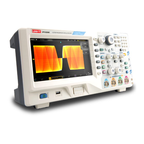
UPO3000E Series Oscilloscope Introduction
Model Overview
Lists the 4 models with analog channels and bandwidth.
Key Features
Highlights display, interface, measurement, and storage capabilities.
Chapter 1 Getting Started Guide
1.1 General Inspection
Steps for inspecting the oscilloscope for transport damage and attachments.
1.2 Before Use
Steps for quick verification of normal operations, including power and probe connection.
1.3 Front Panel
Front Panel Controls Overview
Identifies and describes the numbered controls on the front panel.
1.5 Operation Panel Controls
Vertical Control Functions
Adjusts vertical position and scale for waveforms.
Horizontal Control Functions
Adjusts horizontal position, scale, and time base.
Trigger Control Functions
Manages trigger mode, level, and force functions.
Basic Operation Keys
Covers Auto Set, Run/Stop, Single Trigger, Clear, Print Screen.
Shuttle Knob and Function Keys
Controls for parameter adjustment and menu navigation.
Numeric Keypad and Waveform Recording
Input for parameters and waveform capture setup.
1.6 User Interface Overview
Key Interface Elements
Identifies time base, sampling rate, and horizontal displacement display.
Trigger Status and Details
Displays trigger status and covers source, type, and level settings.
Vertical Channel Status
Displays activation, coupling, bandwidth, scale, and probe attenuation.
1.7 Special Symbols Introduction
Menu Navigation Symbols
Explains symbols for next level, drop-down, options, and page indicators.
Chapter 2 Vertical Channel Settings
Channel Management and Coupling
Manages channel states and sets coupling modes (DC, AC, Grounding).
Bandwidth Limitation and Probe Settings
Limits bandwidth and sets probe attenuation for accuracy.
2.4 VOLTS/DIV Adjustment
Adjusts vertical scale for voltage measurement accuracy.
2.6 Invert and Bias Functions
2.8 Unit Selection
Selects amplitude units (V, A, W, U) for channels.
Chapter 3 Horizontal System Settings
3.1 Horizontal Scale
Adjusts time base scale for horizontal display.
3.2 ROLL Mode
Displays waveform trend chart in real-time.
3.3 Extended Window
Magnifies waveforms horizontally for detail viewing.
3.4 Independent Time Base
Allows different time bases for multiple channels.
3.5 Trigger Hold-off
Sets delay before re-enabling trigger for complex waveforms.
Chapter 4 Sampling System Settings
4.1 Sampling Rate and Effects
Explains sampling process and effects of low sampling rates.
4.2 Acquisition Mode Options
Covers Normal, Peak, High Resolution, Envelope, and Average modes.
4.3 Memory Depth
Sets waveform point storage capacity.
Chapter 5 Trigger System Settings
5.1 Trigger System Interpretation
Explains trigger source, modes, coupling, sensitivity, and pre-trigger.
5.2 Edge Trigger Configuration
Sets up edge triggers based on signal slope.
5.3 Pulse Width Trigger
Triggers based on pulse width conditions and polarity.
5.4 Video Trigger
Triggers on video signals based on format and synchronization.
5.5 Slope Trigger
Triggers based on signal slope rise or fall.
5.6 Runt Trigger
Triggers on pulses that cross one level but not another.
5.7 Window Trigger
Triggers when signal crosses high or low levels.
5.8 Delay Trigger
Triggers based on time difference between two signal edges.
5.9 Timeout Trigger
Triggers when time interval exceeds a set timeout.
5.10 Duration Trigger
Triggers based on the duration of specified codes.
5.11 Setup/Hold Trigger
Triggers based on setup and hold times of data/clock signals.
5.12 Nth Edge Trigger
Triggers on the Nth edge after a specified idle time.
5.13 Code Pattern Trigger
Triggers based on specified code patterns (AND logic).
Chapter 6 Protocol Decoding
6.1 RS232 Decoding Settings
Configures RS232 protocol decoding and trigger conditions.
6.2 I2C Decode Configuration
Sets up I2C protocol decoding, sources, and trigger conditions.
6.3 USB Decode Setup
Configures USB protocol decoding, speed, and trigger conditions.
6.4 CAN Decode Options
Sets up CAN protocol decoding, signal type, and trigger conditions.
6.5 SPI Decode Parameters
Configures SPI protocol decoding, sources, and trigger conditions.
Chapter 7 Mathematical Operation
7.1 Mathematical Function
Performs basic arithmetic operations (+, -, *, /) on channels.
7.2 FFT Analysis
Converts time-domain to frequency-domain signals for analysis.
7.3 Logic Operation
Performs logical operations (AND, OR, NOT, XOR) on waveforms.
7.4 Digital Filter
Applies digital filters (low pass, high pass, etc.) to signals.
7.5 Advanced Operation
Allows custom mathematical expressions using channels and operators.
Chapter 8 Display System Settings
8.1 Waveform Display Settings
Configures display type, format, brightness, persist, and color.
8.2 XY Mode Usage
Displays waveforms in XY mode for phase difference analysis.
Chapter 9 Automatic Measurement
9.1 Parameter Measurement Overview
Lists 34 types of automatic waveform parameters measured.
9.2 Automatic Measurement Menu
Options for signal source, all parameters, and user-defined parameters.
9.3 All Parameters Measurement
Measures all 34 parameters simultaneously.
9.4 User Defined Parameters
Interface for selecting and displaying custom parameters.
Chapter 10 Cursor Measurement
10.1 Time Measurement
Measures time difference and frequency using cursors.
10.2 Voltage Measurement
Measures voltage values using cursors.
Chapter 11 Storage and Load
11.1 Setting Storage and Load
Saves and loads oscilloscope settings to/from DSO or USB.
11.2 Waveform Storage and Load
Saves and loads waveforms to/from DSO or USB.
11.3 Print Screen Function
Saves current screen to BMP format on USB.
Chapter 12 Auxiliary Function Settings
12.1 System Function Settings
Covers self-correcting, system info, language, and menu display.
Auxiliary Function Settings - Part 2
Frequency Meter and Output Settings
Configures frequency meter, AUX output, backlight, and network settings.
Backlight Brightness and Clear Data
Adjusts screen brightness and clears stored data.
Network Settings
Configures network interface, IP type, and IP address.
Chapter 13 Additional Function Keys
13.1 Auto Setting
Automatically adjusts settings for simple signals.
13.2 Run / Stop Control
Controls waveform acquisition state (run or stop).
13.3 Clear Function
Clears the loaded REF waveform from the screen.
13.4 Factory Setting
Resets the oscilloscope to its default factory settings.
13.4 Factory Setting Defaults
Vertical and Horizontal System Defaults
Default settings for vertical and horizontal system parameters.
Trigger and Display Defaults
Default settings for trigger system and display parameters.
Other System Defaults
Default settings for measurement, storage, and interface.
Chapter 14 System Prompts and Troubleshooting
14.1 System Prompt Information
Explains common system prompts and their meanings.
14.2 Trouble Shooting Guide
Addresses issues like black screen, no waveform, and unstable display.
Chapter 15 Technical Index
Input Specifications
Details input coupling, impedance, probe attenuation, and voltage limits.
Vertical Specifications
Lists model, bandwidth, rise time, resolution, scale, and limits.
Chapter 15 Technical Index (Continued)
Horizontal and Sampling Specifications
Details timing, capture rate, sampling modes, and memory depth.
Chapter 15 Technical Index (Continued)
Trigger Specifications Overview
Lists trigger level range, modes, hold-off, and suppression.
Advanced Trigger Specifications
Details specs for window, N-edge, delay, timeout, duration triggers.
Chapter 15 Technical Index (Continued)
Setup/Hold, Slope, Video, Code Trigger Specs
Specifications for setup/hold, slope, video, and code triggers.
RS232 Decode Specifications
Lists RS232 trigger conditions, baud rate, and data byte width.
Chapter 15 Technical Index (Continued)
I2C, SPI, USB, CAN Decode Specifications
Details specifications for I2C, SPI, USB, and CAN decode functions.
Chapter 15 Technical Index (Continued)
Measurement and Math Specifications
Covers cursor, auto measurement, and math operation specs.
Display and Interface Specifications
Details display types, resolution, color, duration, and interfaces.
Chapter 16 Accessories
Appendix A Accessories and Options
Lists included accessories and optional items for purchase.
Appendix B Maintenance and Cleaning
Guidelines for general maintenance and cleaning the instrument.
Need help?
Do you have a question about the UPO3252E and is the answer not in the manual?
Questions and answers