Table of Contents
Advertisement
Installation, use and maintenance instructions
Manuel d'entretien
Installatie-, gebruiks- en onderhoudsvoorschriften
Oil burners
GB
Brûleurs fioul
F
Stookoliebranders
NL
One stage operation
Fonctionnement à 1 allure
Eentrapsbranders
CODE
8099000
8099010
8099030
MODEL - MODELE
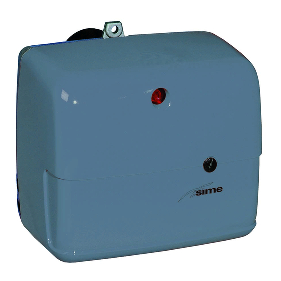
SIME MACK 3
SIME MACK 4
SIME MACK 5
TYPE
514 T1R
515 T3R
515 T5R
2902683 (0)
Advertisement
Table of Contents

Summarization of Contents
Burner Description
Burner Components
Lists the essential components included with the burner unit.
Technical Data
Technical Specifications
Details key operational parameters like output, fuel type, and electrical supply.
Working Field Diagrams
Illustrates operational ranges based on combustion chamber pressure and oil output.
Overall Dimensions
Provides physical measurements for the burner and its flange.
Installation
Boiler Fixing Procedure
Step-by-step instructions for securely mounting the burner to the boiler.
Hydraulic System Setup
Explains oil line connections, filter requirements, and pump priming.
Electrical Wiring Diagram
Outlines the electrical connections and control box configuration.
Accessing the Photoresistance
Guide on locating and accessing the photoresistance for maintenance.
Working
Combustion Adjustment Guide
Procedures for fine-tuning combustion parameters and selecting the correct nozzle.
Recommended Nozzle Types
Lists compatible nozzle manufacturers and types for optimal performance.
Electrode Setting Instructions
Detailed steps for correctly positioning the ignition electrodes.
Air Damper Adjustment Guide
Methods for regulating the air intake using the burner's damper system.
Pump Pressure Setting
Information on the factory-set pump pressure value.
Fuel Heating System
Explains the function of the pre-heater and its indicator lights.
Burner Start-up Sequence
Visual representation of normal and fault-related burner ignition cycles.


Need help?
Do you have a question about the MACK 4 and is the answer not in the manual?
Questions and answers