Table of Contents
Advertisement
Installation, use and maintenance instructions
Manuel d'entretien
Installatie-, gebruiks- en onderhoudsvoorschriften
Oil burners
GB
Brûleurs fioul
F
Stookoliebranders
NL
One stage operation
Fonctionnement à 1 allure
Eentrapsbranders
CODE
8099000
8099010
8099030
MODEL - MODELE
SIME MACK 3
SIME MACK 4
SIME MACK 5
TYPE
514 T1R
515 T3R
515 T5R
2902683 (0)
Advertisement
Table of Contents

Subscribe to Our Youtube Channel
Related Manuals for Sime MACK 3


Summary of Contents for Sime MACK 3
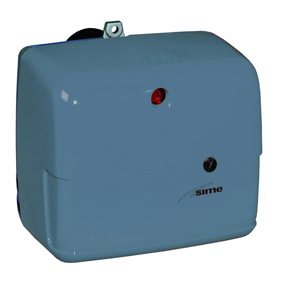
- Page 1 Installatie-, gebruiks- en onderhoudsvoorschriften Oil burners Brûleurs fioul Stookoliebranders One stage operation Fonctionnement à 1 allure Eentrapsbranders CODE MODEL - MODELE TYPE 8099000 SIME MACK 3 514 T1R 8099010 SIME MACK 4 515 T3R 8099030 SIME MACK 5 515 T5R 2902683 (0)
-
Page 3: Table Of Contents
INDEX BURNER DESCRIPTION ... . . 1 WORKING ..... . . 1.1 Burner equipment . -
Page 4: Technical Data
2. TECHNICAL DATA 2.1 TECHNICAL DATA Model MACK 3 MACK 4 MACK 5 Output kg/h 1.4 – 2.2 2.0 – 3.2 2.8 – 3.9 Thermal power 16.6 – 26 23.8 – 37.9 33.3 – 46.2 = 11.86 kWh/kg) Fuel Light oil, max. viscosity at 20°C: 6 mm ±... -
Page 5: Overall Dimensions
Flange Burner D6262 D5908 ø Model MACK 3 MACK 4 - MACK 5 3. INSTALLATION 3.1 BOILER FIXING Put on the flange (1) the screw and two nuts, (see fig. 2). ➤ Widen, if necessary, the insulating gasket holes (5). -
Page 6: Hydraulic Systems
3.2 HYDRAULIC SYSTEMS The burner is designed to allow entry of the flexible oil-lines on either side of the burner. WARNING: Fig. 4 It is necessary to install a filter on the fuel supply line. ■ The standard filter code 6276200 and that one with recirculation code 6276201 are available on request. -
Page 7: Electrical Wiring
3.3 ELECTRICAL WIRING NOTES: WARNING – Wires of 1 mm 2 section . DO NOT EXCHANGE NEUTRAL WITH PHASE – The electrical wiring carried out by the installer must be in compliance with the rules in force in the 50Hz 230V Country. -
Page 8: Working
■ ADJUSTMENTS CARRIED OUT IN FACTORY FOR SIME BOILERS The values shown in the table are measured on a SIME boiler (as per EN 267). They refer to 12.5% CO 2 at sea level and with light oil and room temperature of 20 °C. -
Page 9: Electrodes Setting
4.3 ELECTRODES SETTING IMPORTANT: Fig. 11 ATTENTION THESE DIMENSIONS 4 ± 0.3 mm MUST BE OBSERVED Before removing or assembling the nozzle, loosen the screw (B, fig. 11) and move the electrodes ahead. D5230 – 4.4 AIR DAMPER ADJUSTMENT, (see fig. 12) The mobile air damper (1) operated by the jack (2) assures the com- Fig. -
Page 10: Burner Start-Up Cycle
4.7 BURNER START-UP CYCLE Normal Lock-out due to failure to light Thermostat Heater Orange led Green led and motor Ignition transformer Oil valve Flame Lock-out lamp D5927 120 s 12 s 120 s 12 s Lock out is indicated by a lamp on the control box (3, fig. 1, page 1). 5. -
Page 11: Faults / Solutions
6. FAULTS / SOLUTIONS Here below you can find some causes and the possible solutions for some problems that could cause a failu- re to start or a bad working of the burner. A fault usually makes the lock-out lamp light which is situated inside the reset button of the control box (3, fig. - Page 12 Fonderie Sime S.p.A. - via Garbo, 27 - 37045 Legnago (Vr) - Italy Tel. +39 / 0442 631111 - Export Division fax number +39 / 0442 631293 - Sime Service fax number +39 / 0442 631292...
Need help?
Do you have a question about the MACK 3 and is the answer not in the manual?
Questions and answers