Table of Contents
Advertisement
Advertisement
Table of Contents

Related Manuals for Sime MACK 6


Summary of Contents for Sime MACK 6
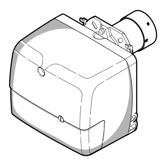
- Page 1 Installation, use and maintenance instructions Manuel d’entretien Installatie-, gebruiks- en onderhoudsvoorschriften Oil burner Brûleur fioul Stookoliebrander One stage operation Fonctionnement à 1 allure Eentrapsbranders CODE MODEL - MODELE TYPE 8099050 SIME MACK 6 412 T 2902684 (0)
-
Page 2: Table Of Contents
INDEX BURNER DESCRIPTION ... . . 1 4.2 Nozzles recomended....1.1 Burner equipment ....1 4.3 Maintenance position . -
Page 3: Technical Data
2. TECHNICAL DATA 2.1 TECHNICAL DATA Model MACK 6 – – Output - Thermal power 10 kg/h 120 kW Fuel Light oil, max. viscosity at 20°C: 6 mm ± Electrical supply Single phase, 50Hz 230 V Motor Run current 0.80 A – 2850 rpm – 298 rad/s 4 µF... -
Page 4: Installation
3. INSTALLATION 3.1 BOILER FIXING Put on the flange (1) the screw and two nuts, (see fig. 2). Widen, if necessary, the insulating gasket holes (5). Fix the flange (1) to the boiler door (4) using screws (2) and (if necessary) the nuts (3) interposing the insulating gasket (5), (see fig. -
Page 5: Hydraulic Systems
3.2 HYDRAULIC SYSTEMS The burner is designed to allow entry of the flexible oil-lines on either side of the burner. WARNING: Fig. 4 It is necessary to install a filter on the fuel supply line. The standard filter code 6276200 and that one with recirculation code 6276201 are available on request. -
Page 6: Electrical Wiring
3.3 ELECTRICAL WIRING NOTES: WARNING – Wires of 1 mm 2 section . DO NOT EXCHANGE NEUTRAL WITH PHASE – The electrical wiring carried out by the installer must be in compliance with the rules in force in the 50Hz 230V Country. -
Page 7: Working
ADJUSTMENTS FOR SIME BOILERS The values shown in the table are measured on a SIME boiler (as per EN 267). They refer to 12.5% CO 2 at sea level and with light oil and room temperature of 20 °C. -
Page 8: Maintenance Position
4.3 MAINTENANCE POSITION Access to the combustion head, electrodes and nozzle, (see fig. 10). Remove the burner out of the boiler, after loosing the fixing nut to the flange. Hook the burner to the flange (1), by removing the combustion head (2) after loosing the fixing screws (3). Remove the electrodes assembly (5) from the nozzle-holder (4) after loosing its fixing screw (B, fig. -
Page 9: Air Damper Adjustment
TURN TO THE RIGHT: (sign +) In order to increase the volume of air entering the combus- Fig. 12 tion chamber and thus diminishing its pressure. Terminal plane of the blast tube There is a reduction of CO and the adhesion of the flame to the air diffuser disc improves. -
Page 10: Burner Start-Up Cycle
4.8 BURNER START-UP CYCLE Normal Lock-out due to failure to light Thermostat Green led and motor Ignition transformer Oil valve Flame Lock-out lamp D5029 Lock out is indicated by a lamp on the control box (3, fig. 1, page 1). 4.9 ADJUSTMENTS, TO AVOID FLAME - DETACHMENT, AT BURNER - IGNITION This inconvenience can occur, when the temperature of the gas-oil decreases below + 5 °C. -
Page 11: Faults / Solutions
6. FAULTS / SOLUTIONS Here below you can find some causes and the possible solutions for some problems that could cause a fail- ure to start or a bad working of the burner. A fault usually makes the lock-out lamp light which is situated inside the reset button of the control box (3, fig. - Page 12 Fonderie Sime S.p.A. - via Garbo, 27 - 37045 Legnago (Vr) - Italy Tel. +39 / 0442 631111 - Export Division fax number +39 / 0442 631293 - Sime Service fax number +39 / 0442 631292...
Need help?
Do you have a question about the MACK 6 and is the answer not in the manual?
Questions and answers