
Related Manuals for Pepperl+Fuchs SK3


Summarization of Contents
1 Introduction
1.2 Target Group, Personnel
Identifies the intended audience and qualification requirements for product handling.
1.3 Symbols Used
Explains symbols used for warnings and informative messages in the document.
2 Product Specifications
2.1 Overview and Application
Describes the function, purpose, and application areas of the PROFIBUS Power Hub.
2.7 Technical Data
Lists detailed technical specifications and parameters for the product.
2.8 Dimensions
Shows the physical dimensions of the components.
6 Operation
6.1 Built-In Slave (BIS) Description
Explains the functionality and configuration of the built-in slave.
6.3 Acyclic Data Exchange with Built-In Slave via Device Type Manager
Covers parameterization and diagnostics using DTM and acyclic communication.
6.4 Redundant Operation
Details the configuration and behavior of the system in redundant mode.
7 Advanced Diagnostics with the PROFIBUS Power Hub
7.1 Advanced Diagnostics Infrastructure
Outlines the architecture and components for advanced diagnostics.
10 Parameter Reference List
10.1 General Parameters
Lists and describes general device parameters and their meanings.
10.2 Diagnostic Parameters
Details parameters related to device and segment diagnostics.
1 Introduction
Warning Messages
Explains different levels of warning messages and their meanings.
Informative Symbols
Describes symbols used to convey important information.
2 Product Specifications
2.1 Overview and Application
Describes the function, purpose, and application areas of the PROFIBUS Power Hub.
2 Product Specifications
2.2 Coupling
Details the function and technical aspects of the DP/PA coupling mechanism.
2 Product Specifications
2.3 Segment Supply
Explains how segments are supplied with power and communication signals.
2.4 System Components
Lists and describes the various hardware components of the system.
2 Product Specifications
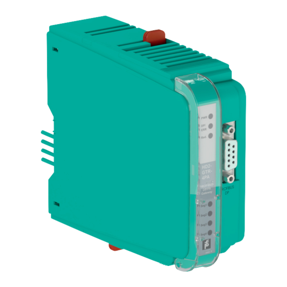
Gateway Module
Describes the HD2-GTR-4PA gateway module and its functions.
Fieldbus Power Supply Modules
Details the available power supply modules and their specifications.
Diagnostic Modules
Explains the basic and advanced diagnostic modules and their capabilities.
2 Product Specifications
2.5 Recommended System Combinations
Presents typical system configurations and their components.
2 Product Specifications
2.5 Recommended System Combinations
Presents typical system configurations and their components.
2 Product Specifications
2.5 Recommended System Combinations
Presents typical system configurations and their components.
2 Product Specifications
2.6 Component Overview
Provides a visual and descriptive overview of system components.
2 Product Specifications
2.6 Component Overview
Provides a visual and descriptive overview of system components.
2.7 Technical Data
Lists detailed technical specifications and parameters for the product.
2 Product Specifications
2.7 Technical Data
Lists detailed technical specifications and parameters for the product.
2 Product Specifications
2.7 Technical Data
Lists detailed technical specifications and parameters for the product.
2 Product Specifications
2.8 Dimensions
Shows the physical dimensions of the components.
3 Installation and Commissioning
Safety Warnings
Provides critical safety information regarding explosion hazards and proper installation.
3.1 Mounting and Dismounting
Details the procedures for physically installing and removing the device.
3 Installation and Commissioning
3.1 Mounting and Dismounting
Details the procedures for physically installing and removing the device.
Mounting of Fieldbus Motherboards on DIN Mounting Rail
Specific steps for mounting motherboards onto a DIN rail.
Mounting Plug-In Modules on the Motherboard
Instructions for installing modules onto the motherboard.
3 Installation and Commissioning
3.2 Shielding/Grounding
Explains the importance and methods for shielding and grounding the system.
3.2.1 Connection to Equipotential Bonding System
Details how to connect the system to an equipotential bonding system.
Ground Connection Cable Installation
Provides guidance on connecting the ground cable.
3 Installation and Commissioning
Connecting the ground connection cable
Detailed steps for connecting the ground cable to the clamp.
3 Installation and Commissioning
3.3 Connections
Illustrates and describes the various connection points on the device.
3 Installation and Commissioning
3.3 Connections
Illustrates and describes the various connection points on the device.
Diagnostic Information Transmission Methods
Explains different ways to transmit diagnostic information from the system.
4 Hazardous Area Installation and Use
4.1 Installation in Zone 2, Category 3G
Provides specific installation guidelines for hazardous areas (Zone 2, Category 3G).
Hazardous Area Safety Precautions
Details critical safety measures required for installation in hazardous environments.
5 PROFIBUS Commissioning
5.1 Device Address Assignment
Covers the process of assigning slave addresses to the gateway.
5.2 Cyclic Data Exchange
Explains how to configure cyclic data exchange for the system.
5 PROFIBUS Commissioning
5.2.1 Information on GSD File Conversion
Provides guidance on converting GSD files for PROFIBUS PA devices.
5 PROFIBUS Commissioning
GSD Converter
Introduces the tool for converting GSD files.
Download GSD Converter Tool
Instructions on how to download the GSD converter software.
5 PROFIBUS Commissioning
5.2.3 Information on Watchdog Time (TWD)
Explains the function and configuration of watchdog time.
5 PROFIBUS Commissioning
Information on I/O Cycle Time
Provides information and calculation methods for I/O cycle times.
5 PROFIBUS Commissioning
5.2.4 Retry Limits
Discusses adjusting retry limits, especially for fiberoptical communication.
5.2.5 Device Type Manager (DTM): Installation and Commissioning
Covers the installation and commissioning of the DTM.
5 PROFIBUS Commissioning
Creating the Project Tree
Instructions for setting up the project structure in PACTware.
5 PROFIBUS Commissioning
Entering the Assigned Built-In Slave Address in the DTM
Details how to input the BIS address into the DTM.
DTM Address Update Note
Notes regarding the display of address changes in the DTM.
5 PROFIBUS Commissioning
Advanced Diagnostic Module (ADM) Engineering
Explains how to engineer the Advanced Diagnostic Module.
6 Operation
6.1 Built-In Slave (BIS) Description
Explains the functionality and configuration of the built-in slave.
Cyclic Data Exchange
Discusses the exchange of data during cyclic communication.
Parameterization Options (Channel Assignment)
Outlines the available parameterization modules for channel configuration.
6 Operation
Diagnostics (ADM alarm observer)
Describes the ADM alarm observer function for diagnostics.
Diagnostics (Slave Diagnostics)
Details the diagnostic information provided by the slave.
6 Operation
6.2 Coupled Slaves
Discusses how PROFIBUS PA slaves are coupled and their behavior.
6.3 Acyclic Data Exchange with Built-In Slave via Device Type Manager
Covers parameterization and diagnostics using DTM and acyclic communication.
DTM Data Loss Note
Warns about potential data loss when using DTM online settings.
6 Operation
Connecting the DTM to the HD2-GTR-4PA
Steps to establish a connection between the DTM and the gateway.
Opening the Offline Dialog
How to access the offline parameterization dialog in DTM.
Opening the Online Dialog
How to access the online parameterization dialog in DTM.
Opening the Diagnostics Dialog
How to access the diagnostics dialog in DTM.
6 Operation
6.3.2 Overview of the Device Type Manager User Interface
Provides a visual guide to the DTM interface elements.
Printing Diagnostic Information
Steps for printing diagnostic reports from the DTM.
6 Operation
6.3.3 HD2-GTR-4PA Structure Diagrams
Shows the hierarchical structure of the DTM interface for the gateway.
6.3.4 Watchdog Time in the Device Type Manager
Explains the watchdog time settings within the DTM.
6 Operation
Setting the Watchdog Time to "Fixed" in the DTM
How to configure a fixed watchdog time in the DTM.
6.3.5 PROFIBUS PA Retry Limit in the Device Type Manager
Covers setting the PA retry limit via the DTM.
6.3.6 Restart Functions, Redundancy Switchover, and Firmware Update
Details additional functions like restart, switchover, and firmware updates.
6 Operation
Performing a Restart
Steps to reboot the gateway.
Performing a Restart with Default Values
Steps to reboot the gateway with its default settings.
Redundancy Switchover
Explanation of redundancy switchover behavior and requirements.
Performing a Redundancy Switchover
Steps to manually initiate a redundancy switchover.
6 Operation
Firmware Download
Steps for downloading and installing firmware updates.
6 Operation
6.4 Redundant Operation
Explains how the system operates in a redundant configuration.
Redundancy Behavior
Details the behavior of the gateway during redundant operation.
6 Operation
6.4 Redundant Operation
Explains how the system operates in a redundant configuration.
Applications with Redundant Operation
Lists scenarios where redundant operation is applicable.
6 Operation
6.4 Redundant Operation
Explains how the system operates in a redundant configuration.
7 Advanced Diagnostics with the PROFIBUS Power Hub
7.1 Advanced Diagnostics Infrastructure
Outlines the architecture and components for advanced diagnostics.
Advanced Diagnostics Connection via PROFIBUS DP
Details the setup for connecting diagnostics via PROFIBUS DP.
7 Advanced Diagnostics with the PROFIBUS Power Hub
7.1 Advanced Diagnostics Infrastructure
Outlines the architecture and components for advanced diagnostics.
Advanced Diagnostics Connection via Diagnostic Bus
Explains the setup for connecting diagnostics via the diagnostic bus.
7 Advanced Diagnostics with the PROFIBUS Power Hub
7.2 PROFIBUS Advanced Diagnostics Integration
Integrates advanced diagnostics into the PROFIBUS system.
Activating the Alarm Observer in the Device Type Manager
Steps to enable the alarm observer function in the DTM.
7 Advanced Diagnostics with the PROFIBUS Power Hub
Advanced Diagnostic Messages in the Gateway DTM
Lists additional diagnostic messages available in the gateway DTM.
Device-specific messages
Specific diagnostic messages related to the gateway device itself.
Segment-specific messages
Specific diagnostic messages related to individual PA segments.
8 Basic Redundancy Concepts
Flying Redundancy
Explains the concept of flying redundancy for masters and slaves.
8 Basic Redundancy Concepts
Flying Redundancy
Explains the concept of flying redundancy for masters and slaves.
8 Basic Redundancy Concepts
System Redundancy
Explains the concept of system redundancy.
10 Parameter Reference List
10.1 General Parameters
Lists and describes general device parameters and their meanings.
PA Master Parameters
Details parameters specific to the PROFIBUS PA master configuration.
10 Parameter Reference List
PA Segment Parameters
Lists parameters related to individual PA segments.
Diagnostic Parameters
Details parameters related to device and segment diagnostics.
10 Parameter Reference List
PA Segment Diagnostic Parameters
Lists diagnostic parameters for PA segments.
Redundancy Partner Parameters
Details parameters for the redundancy partner device.
11 Troubleshooting
Initial Troubleshooting Steps
Provides initial checks to perform when encountering a fault.
11.1 Faults Indicated via LEDs
Helps diagnose faults based on LED indicators on the device.
11 Troubleshooting
11.1 Faults Indicated via LEDs
Helps diagnose faults based on LED indicators on the device.
11.2 Fault Indicated via DTM
Aids in diagnosing faults reported through the Device Type Manager.
11 Troubleshooting
11.2 Fault Indicated via DTM
Aids in diagnosing faults reported through the Device Type Manager.
11.3 Fault Indicated via DCS
Helps diagnose faults indicated by the distribution control system.
DCS Fault Check Note
Notes for checking DCS indications and integration.
11 Troubleshooting
11.3 Fault Indicated via DCS
Helps diagnose faults indicated by the distribution control system.
11.4 Problems with Gateway Operation
Addresses common issues encountered during gateway operation.
11 Troubleshooting
11.4 Problems with Gateway Operation
Addresses common issues encountered during gateway operation.
Need help?
Do you have a question about the SK3 and is the answer not in the manual?
Questions and answers