Table of Contents
Advertisement
®
This publication contains the installation, operation and
maintenance instructions for standard units of the TCN:
Inline Blowers.
• TCN-B
• TCNHS-B
• TCNHE-B
• TCNU-B
• TCNH-D
• TCNE-B
• TCNH-B
• TCNHU-B
Carefully read this publication and any
supplemental documents prior to any
installation or maintenance procedure.
Loren Cook catalog, TCN, provides additional informa-
tion describing the equipment, fan performance, available
accessories and specification data.
For additional safety information, refer to AMCA Publi-
cation 410-96, Safety Practices for Users and Installers of
Industrial and Commercial Fans.
All of the publications listed above can be obtained from:
• lorencook.com
• info@lorencook.com
• 417-869-6474 ext. 166
For information and instructions on special equipment,
contact Loren Cook Company at 417-869-6474.
Receiving and Inspection
Carefully inspect the fan and accessories for any dam-
age and shortage immediately upon receipt of the fan.
• Turn the wheel by hand to ensure it turns freely and does
not bind.
• Inspect dampers for free operation of all moving parts.
• Record on the Delivery Receipt any visible sign of damage.
Handling
Lift the fan by foot brackets.
NOTICE! Never lift by the shaft, motor or housing.
TCN-B
TCN IO&M
INSTALLATION, OPERATION AND MAINTENANCE MANUAL
• TCNS-B
• TCN-D
1
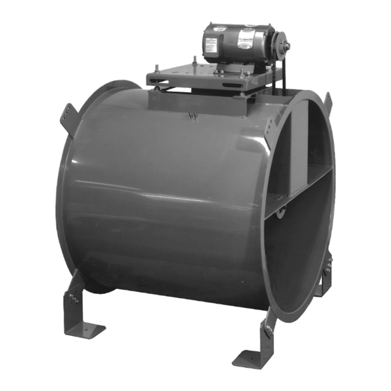
Tubular Centrifugal Inline Fans
Rotating Parts & Electrical Shock Hazard:
Fans should be installed and serviced by qualified person-
nel only.
Disconnect electric power before working on unit (prior to
removal of guards or entry into access doors).
Follow proper lockout/tagout procedures to ensure the unit
cannot be energized while being installed or serviced.
A disconnect switch should be placed near the fan in order
that the power can be swiftly cut off, in case of an emer-
gency and in order that maintenance personnel are pro-
vided complete control of the power source.
Grounding is required. All field-installed wiring must be
completed by qualified personnel. All field installed wiring
must comply with National Electric Code (NFPA 70) and all
applicable local codes. Ensure the power supply (voltage,
frequency and current carrying capacity of wires) is in ac-
cordance with the motor nameplate.
Fans and blowers create pressure at the discharge and
vacuum at the inlet. This may cause objects to get pulled
into the unit and objects to be propelled rapidly from the
discharge. The discharge should always be directed in a
safe direction and inlets should not be left unguarded. Any
object pulled into the inlet will become a projectile capable
of causing serious injury or death.
When air is allowed to move through a non-powered fan,
the impeller can rotate, which is referred to as windmill-
ing. Windmilling will cause hazardous conditions due to
unexpected rotation of components. Impellers should be
blocked in position or air passages blocked to prevent draft
when working on fans.
Friction and power loss inside rotating components will
cause them to be a potential burn hazard. All components
should be approached with caution and/or allowed to cool
before contacting them for maintenance.
Under certain lighting conditions, rotating components
may appear stationary. Components should be verified to
be stationary in a safe manner, before they come into con-
tact with personnel, tools or clothing.
Failure to follow these instructions could result in death or
serious injury.
The attachment of roof mounted fans to the roof curb as
well as the attachment of roof curbs to the building struc-
ture must exceed the structural requirements based on the
environmental loading derived from the applicable build-
ing code for the site. The local code official may require
variations from the recognized code based on local data.
The licensed engineer of record will be responsible for pre-
scribing the correct attachment based on construction ma-
terials, code requirements and environmental effects spe-
cific to the installation.
TCN
B51143-003
Advertisement
Table of Contents

Related Manuals for COOK TCNH-B


Summarization of Contents
WARNING - Safety Hazards
Rotating Parts & Electrical Shock Hazard
Fans should be installed and serviced by qualified personnel only. Disconnect power before servicing.
Grounding Requirements
All field-installed wiring must be completed by qualified personnel and comply with electrical codes.
Discharge and Inlet Hazards
Fans create pressure and vacuum; objects pulled into the inlet can become projectiles causing injury.
Windmilling Hazard
Non-powered fans can rotate due to air movement, posing hazardous conditions for components.
Burn Hazard from Rotating Parts
Friction and power loss cause rotating components to be a potential burn hazard.
Visual Hazard of Rotating Parts
Rotating components may appear stationary under certain lighting conditions, requiring verification.
Structural Mounting Requirements
Roof fan mounting must exceed structural requirements based on environmental loading.
Receiving, Inspection, and Handling
Receiving and Inspection Steps
Inspect fan and accessories for damage/shortage upon receipt. Check wheel and damper operation.
Proper Lifting Method
Lift the fan by foot brackets only. Never lift by the shaft, motor, or housing.
Storage and Isolation Installation
Standard Storage Procedures
Fill bearings with grease/oil, store in original crate, protect from dust, debris, and weather.
Outdoor Storage Precautions
Cover openings, rotate wheel, operate dampers, and inspect unit regularly for good condition.
Motor Mounting for Large Motors
Motors 5 HP and larger are shipped loose and must be field mounted on the motor mounting plate.
Vibration and Noise Control
Isolators are recommended to prevent vibration and noise transfer to the building structure.
Floor Mounted Isolator Installation
Instructions for installing floor-mounted spring or rubber-in-shear isolators for fans.
Ceiling Mounted Isolator Installation
Instructions for installing ceiling-mounted spring or rubber-in-shear isolators for fans.
Non-Ducted Inlet Clearance
For open inlets, the fan must be placed one fan wheel diameter away from walls and bulkheads.
Free Discharge Considerations
Avoid free discharge into the plenum to prevent lost efficiency and static regain.
Duct Installation and Belt Alignment
Duct Turns Clearance
Allow three fan wheel diameters for inlet duct turns and three duct diameters for discharge.
Wheel-to-Inlet Clearance
Critical for fan performance; adjust overlap by moving wheel on shaft and repositioning inlet cone.
Belt Tension Adjustment
Adjust motor plate for proper tension, achieving approximately 1/4" deflection per foot of center distance.
Pulley Alignment
Align pulleys by adjusting motor pulley setscrew and motor shaft position for proper gap tolerance.
Wiring and Electrical Setup
Wiring Installation Slack
Leave slack in wiring to allow for motor movement when adjusting belt tension.
Variable Frequency Drive (VFD) Use
Motors must be VFD compatible; consult manufacturer for recommendations and line reactors.
Grounding Requirements
Connect fan frame, motor, and VFD to a common earth ground to prevent transient voltages.
Resonant Frequency Management
Perform coast-down tests and use VFD skip frequency to remove resonant frequencies.
Single Phase Motor Wiring
Diagrams for single speed, single phase, and dual voltage motors, including grounding connections.
Three Phase Motor Wiring
Diagrams for 3-phase, 9-lead, and 2-speed motors, showing Y/Delta and speed connections.
Motor/Damper Schematic
Schematic for typical fan motor and damper motor connections, including transformer use.
Operation and Maintenance Checks
Wheel Rotation Check
Test fan rotation to ensure it matches the marked arrow direction.
Final Installation Steps
Inspect fasteners, voltage, and accessories; tighten as necessary after installation.
Pre-Start Checks
Lock out power, check fasteners, alignment, wiring, clearance, and secure all access doors.
Start-Up Procedure
Turn on fan at lowest speed, inspect rotation, vibration, noise, bearings, and belts.
Initial Interval Inspections
Inspect fan at 30-minute, 8-hour, and 24-hour intervals after operation for proper function.
Recommended Torque Values
Torque specifications for setscrews and hold-down bolts are provided for proper tightening.
Periodic Maintenance Schedule
Schedule inspections for bolts, belts, bearings, vanes, isolators, and cleanliness as recommended.
Lubrication and Component Replacement
Fan Bearing Lubrication
Lubricate fan bearings while operating, avoid over-greasing, and follow schedule based on conditions.
Motor Bearing Lubrication
Follow motor nameplate instructions; some motors require no maintenance, others periodic disassembly.
Changing Fan Shaft Speed
Adjust variable pitch pulleys to change fan speed by opening or closing pulley grooves.
Pulley and Belt Replacement
Instructions for removing/installing pulleys and belts, including cleaning, alignment, and tension.
Bearing and Wheel Replacement
Bearing Replacement Steps
Remove belts, bearing cover, inlet cone, and sheave; loosen setscrews and remove shaft/bearings.
TCN Wheel Replacement
Remove inlet cone, use puller if needed, adjust wheel for inlet alignment, and tighten setscrews.
TCNH Wheel Replacement
Remove inlet cone, use puller with shoulder, adjust wheel for inlet alignment, and tighten setscrews.
Troubleshooting Common Issues
Low Capacity or Pressure Issues
Check rotation direction, inlet conditions, and wheel alignment for low performance.
Vibration and Noise Issues
Inspect wheel, belts, fasteners, speed, rotation, bearings, and debris for excessive vibration/noise.
Overheated Motor Issues
Check wiring, rotation, cooling air, inlet clearance, RPM, voltage, lubrication, and belt tension.
Need help?
Do you have a question about the TCNH-B and is the answer not in the manual?
Questions and answers