Table of Contents
Advertisement
Quick Links
®
This publication contains the installation, operation and
maintenance instructions for standard units of the ACSC:
Smoke Control Fans.
• ACSC/ACSC-HP/ACSC-XP
Carefully read this publication and any
supplemental documents prior to any
installation or maintenance procedure.
Loren Cook catalog, AC, provides additional information
describing the equipment, fan performance, available ac-
cessories and specification data.
For additional safety information, refer to AMCA Publi-
cation 410-96, Safety Practices for Users and Installers of
Industrial and Commercial Fans.
All of the publications listed above can be obtained from:
• lorencook.com
• info@lorencook.com
• 417-869-6474 ext. 166
For information and instructions on special equipment,
contact Loren Cook Company at 417-869-6474.
Receiving and Inspection
Carefully inspect the fan and acces-
sories for any damage and shortage
immediately upon receipt of the fan.
• Turn wheel by hand to ensure it turns
freely and does not bind
• Record on the Delivery Receipt any
visible sign of damage
Handling
Lift the fan by the shipping carton or lifting lugs provided
under top cap.
NOTICE! Never lift by the shaft, motor or housing.
Storage
If the fan is stored for any length of time prior to installa-
tion, store the fan in its original shipping crate and protect
it from dust, debris and weather.
Damper
Use of any backdraft dampers is NOT permitted. Fire
dampers and/or smoke dampers may be required in a
smoke control system. These dampers must meet the re-
quirements determined by the local code authority.
ACSC
ACSC IO&M
INSTALLATION, OPERATION AND MAINTENANCE MANUAL
Rotating Parts & Electrical Shock Hazard:
Fans should be installed and serviced by qualified person-
nel only.
Disconnect electric power before working on unit (prior to
removal of guards or entry into access doors).
Follow proper lockout/tagout procedures to ensure the unit
cannot be energized while being installed or serviced.
A disconnect switch should be placed near the fan in order
that the power can be swiftly cut off, in case of an emer-
gency and in order that maintenance personnel are pro-
vided complete control of the power source.
Grounding is required. All field-installed wiring must be
completed by qualified personnel. All field installed wiring
must comply with National Electric Code (NFPA 70) and all
applicable local codes. Ensure the power supply (voltage,
frequency and current carrying capacity of wires) is in ac-
cordance with the motor nameplate.
Fans and blowers create pressure at the discharge and
vacuum at the inlet. This may cause objects to get pulled
into the unit and objects to be propelled rapidly from the
discharge. The discharge should always be directed in a
safe direction and inlets should not be left unguarded. Any
object pulled into the inlet will become a projectile capable
of causing serious injury or death.
When air is allowed to move through a non-powered fan,
the impeller can rotate, which is referred to as windmill-
Lifting Lugs
ing. Windmilling will cause hazardous conditions due to
unexpected rotation of components. Impellers should be
blocked in position or air passages blocked to prevent draft
when working on fans.
Friction and power loss inside rotating components will
cause them to be a potential burn hazard. All components
should be approached with caution and/or allowed to cool
before contacting them for maintenance.
Under certain lighting conditions, rotating components
may appear stationary. Components should be verified to
be stationary in a safe manner, before they come into con-
tact with personnel, tools or clothing.
Failure to follow these instructions could result in death or
serious injury.
The attachment of roof mounted fans to the roof curb as
well as the attachment of roof curbs to the building struc-
ture must exceed the structural requirements based on the
environmental loading derived from the applicable build-
ing code for the site. The local code official may require
variations from the recognized code based on local data.
The licensed engineer of record will be responsible for pre-
scribing the correct attachment based on construction ma-
terials, code requirements and environmental effects spe-
cific to the installation.
1
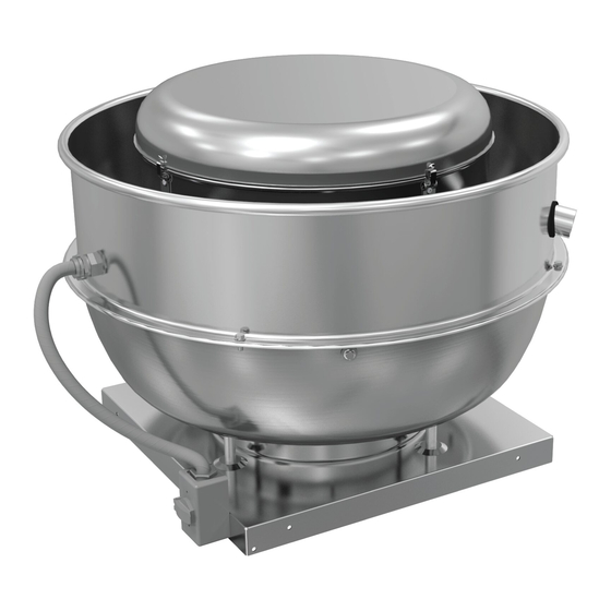
ACSC
Smoke Control Ventilator
B51002-002
Advertisement
Table of Contents

Subscribe to Our Youtube Channel
Related Manuals for COOK ACSC


Summary of Contents for COOK ACSC
- Page 1 Smoke Control Ventilator INSTALLATION, OPERATION AND MAINTENANCE MANUAL ® This publication contains the installation, operation and maintenance instructions for standard units of the ACSC: Smoke Control Fans. Rotating Parts & Electrical Shock Hazard: • ACSC/ACSC-HP/ACSC-XP Fans should be installed and serviced by qualified person- Carefully read this publication and any nel only.
-
Page 2: Wiring Installation
The frequency of inspection depends on the operating conditions and location of the fan. Line ACSC fan is intended for general ventilation, and is UL listed for Smoke Control Systems. The fan should not be used to exhaust corrosive or contaminated air. -
Page 3: Pulley Alignment
Figure 2 indicates where to measure the allowable gap 5/16” 1120 1280 1-1/4”-7 6000 3/8” 1680 1920 for the drive alignment tolerance. All contact points (indi- 1/2” 4200 4800 cated by WXYZ) are to have a gap less than the tolerance 9/16” 5600 6400 ACSC IO&M B51002-002... -
Page 4: Bearing Replacement
Motor Services Should the motor prove defective within a one-year pe- Fan Bearings riod, contact your local Loren Cook representative or your NOTICE! The fan bearings are provided prelubri- nearest authorized electric motor service representative. cated. Any specialized lubrication instructions on... -
Page 5: Wheel Replacement
(normally a quantity of two) are fully removed. Work puller slowly to back wheel off the shaft. Recommended Puller Lisle No. 45000 Steering Wheel Puller. This puller is available at most automotive parts retail outlets. RADIAL CLEARANCE OVERLAP Drilled Hole Location Wheel Puller ACSC IO&M B51002-002... -
Page 6: Parts List
Parts List Drawing Model Size Replacement ACSC Part Description Reference # Part # 708942 ACSC 120–135 708943 150–165 708944 180–195 708945 210–225 708946 708947 1A, 1B 708948 Top Cap Assembly 708949 708950 708951 708952 708953 708954 254381 120–135 254382 150–165 254383 180–195... - Page 7 Replacement Part # Drawing Replacement ACSC Part Drawing Model ACSC Part Model Size Reference # Part # Description Ref. # Size Description Standard 254662 705400 120–135 254663 705401 705402 150–165 254664 705403 705463 180–195 254665 Outer Band 705404 705464 705484 210–225...
-
Page 8: Troubleshooting
Cook Company, General Offices, 2015 East Dale Street, Springfield, Missouri 65803-4637, explaining in writing, in detail, your complaint and referring to the specific model and serial numbers of your fan. Upon receipt by Loren Cook Company of your written complaint, you will be notified, within thirty (30) days of our receipt of your complaint, in writing, as to the manner in which your claim will be handled.
Need help?
Do you have a question about the ACSC and is the answer not in the manual?
Questions and answers