Table of Contents
Advertisement
®
This publication contains the installation, operation and
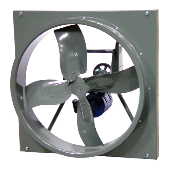
maintenance instructions for standard units of the Propeller
Wall Fans.
• XWD
• XMP / XMPH
• XWHD
• AWD
• XPD
• AWB
• XPHD
• APD
• XLW / XMW
• APB
• XLWH / XMWH
• EWD
• XLP / XLPH
• EWB
Carefully read this publication and any
supplemental documents prior to any
installation or maintenance procedure.
Loren Cook catalog, Propeller Wall, provide additional
information describing the equipment, fan performance,
available accessories and specification data.
For additional safety information, refer to AMCA Publica-
tion 410-96, Safety Practices for Users and Installers of
Industrial and Commercial Fans.
All of the publications listed above can be obtained from:
• lorencook.com
• info@lorencook.com
• 417-869-6474 ext. 166
For information and instructions on special equipment,
contact Loren Cook Company at 417-869-6474.
Receiving and Inspection
Carefully inspect the unit and accessories for any dam-
age and shortage immediately upon receipt of the unit.
• Turn the propeller by hand to ensure it turns freely and
does not bind
• Record on the Delivery Receipt any visible sign of
damage
XLWH
PROPELLER WALL IO&M
PROPELLER WALL
INSTALLATION, OPERATION AND MAINTENANCE MANUAL
• EPD
• EPB
• SWD
• SPB
• SPD
• Exhaust & Supply
models
1
Rotating Parts & Electrical Shock Hazard:
Fans should be installed and serviced by qualified person-
nel only.
Disconnect electric power before working on unit (prior to
removal of guards or entry into access doors).
Follow proper lockout/tagout procedures to ensure the unit
cannot be energized while being installed or serviced.
A disconnect switch should be placed near the fan in order
that the power can be swiftly cut off, in case of an emer-
gency and in order that maintenance personnel are provid-
ed complete control of the power source.
Grounding is required. All field-installed wiring must be
completed by qualified personnel. All field installed wiring
must comply with National Electric Code (NFPA 70) and all
applicable local codes.
Fans and blowers create pressure at the discharge and
vacuum at the inlet. This may cause objects to get pulled
into the unit and objects to be propelled rapidly from the
discharge. The discharge should always be directed in a
safe direction and inlets should not be left unguarded. Any
object pulled into the inlet will become a projectile capable
of causing serious injury or death.
When air is allowed to move through a non-powered fan,
the impeller can rotate, which is referred to as windmill-
ing. Windmilling will cause hazardous conditions due to
unexpected rotation of components. Impellers should be
blocked in position or air passages blocked to prevent draft
when working on fans.
Friction and power loss inside rotating components will
cause them to be a potential burn hazard. All components
should be approached with caution and/or allowed to cool
before contacting them for maintenance.
Under certain lighting conditions, rotating components
may appear stationary. Components should be verified to
be stationary in a safe manner, before they come into con-
tact with personnel, tools or clothing.
Failure to follow these instructions could result in death or
serious injury.
The attachment of roof mounted fans to the roof curb as
well as the attachment of roof curbs to the building struc-
ture must exceed the structural requirements based on the
environmental loading derived from the applicable build-
ing code for the site. The local code official may require
variations from the recognized code based on local data.
The licensed engineer of record will be responsible for pre-
scribing the correct attachment based on construction ma-
terials, code requirements and environmental effects spe-
cific to the installation.
Propeller Wall Fans
B51091-003
Advertisement
Table of Contents

Related Manuals for COOK XWD Series


Summary of Contents for COOK XWD Series
- Page 1 Loren Cook catalog, Propeller Wall, provide additional ed complete control of the power source. information describing the equipment, fan performance, available accessories and specification data.
-
Page 2: Installation
Handling Figure 2 Tolerance Center OFFSET ANGULAR OFFSET/ANGULAR Lift propeller wall fans by attachment to the power Distance assembly. Up through 12” 1/16” NOTICE! Never lift by the shaft, motor or housing. 12” through 48 1/8” Over 48” 1/4” Storage If the fan is stored for any length of time prior to installa- tion, coat the shaft with grease or a rust preventative com- CENTER... -
Page 3: Wiring Diagrams
Wall Fans with Wall Housing 2 Speed, 1 Winding, 3-Phase Motor 1. Remove end guard from the wall housing. High Speed Low Speed 2. Drill a hole through either side panel at a convenient Together Line location and pull the wires through. Do not pull wires Motor through wire guard at the back panel. -
Page 4: Operation
Inspect for the following: • Direction of rotation Lubricants • Excessive vibration Loren Cook Company uses petroleum lubricant in a lith- • Unusual noise ium base conforming to NLGI grade 2 consistency. Other • Bearing noise grades of grease should not be used unless the bearings •... -
Page 5: Relubrication Intervals
1462 1272 1385 Motor Services 1175 Should the motor prove defective within a one-year pe- riod, contact your local Loren Cook representative or your nearest authorized electric motor service representative. PROPELLER WALL IO&M B51091-003... -
Page 6: Bearing Replacement
Pulley and Belt Replacement 15. Tighten the bearing setscrews to the specified torque. 16. Install the pulley and adjust the belt tension. 1. Clean the motor and fan shafts. 17. After 24 hours of continuous operation, tighten the set- 2. Loosen the motor plate mounting bolts to relieve the screws to the appropriate torque. -
Page 7: Typical Installations
Typical Installations (Dimensions are in inches) XLWH Exhaust Fan with Osha Std. Wire Guard. XMWH Wire Guard & Shutter 12-3/4 12-1/2 13-1/4 10-12 16-3/4 16-7/16 17-1/4 Illustrated is the typical installa- 14-16 20-3/4 20-7/16 21-1/4 tion of an exhaust wall fan with an 18-20 24-3/4 24-7/16 25-1/4... -
Page 8: Parts List
Parts List XPD & SPD Exhaust XWD & SWD Exhaust Air Flow Flow Flow Rotation XPHD Supply Exhaust Size 20-24 Size 12-18 Air Flow Rotation Flow Flow Part Description Part Description Motor Stamped Aluminum Propeller Wire Guard Wall Collar Wall Base End Wire Guard Supply Venturi... - Page 9 XLW / XMW XLP / XLPH / XMP / XMPH Exhaust Exhaust Air Flow Air Flow Rotation Supply Supply Air Flow Air Flow Rotation XLWH / XMWH Part Description Exhaust Base Prop Air Flow Venturi Shaft Bearings (2) Motor Motor Plate Driven Sheave Drive Sheave Belt...
- Page 10 Exhaust Exhaust Flow Air Flow Rotation Rotation Supply Supply Flow Air Flow Rotation Rotation Exhaust Exhaust Supply Air Flow 15 14 15 14 Rotation Flow Flow Supply Part Description Part Description Air Flow Power Assembly Shutters Prop Driven Sheave Base Driver Sheave Venturi Belt...
- Page 11 Weather Hood Size 36 to 60 Exhaust Rotation Exhuast Flow Supply Flow Supply Rotation Exhaust Rotation Exhuast Flow Supply Flow Supply Rotation Part Description Part Description Exhaust Supply Top Panel, Piece 1 Bird Screen Support 14 15 Top Panel, Piece 2 1/2”...
-
Page 12: Limited Warranty
Cook Company, General Offices, 2015 East Dale Street, Springfield, Missouri 65803-4637, explaining in writing, in detail, your complaint and referring to the specific model and serial numbers of your fan. Upon receipt by Loren Cook Company of your written complaint, you will be notified, within thirty (30) days of our receipt of your complaint, in writing, as to the manner in which your claim will be handled.
Need help?
Do you have a question about the XWD Series and is the answer not in the manual?
Questions and answers