Advertisement
®
This installation manual provides information for
installing and configuring the Loren Cook Company
Propeller Wall Fans.
• XWD
• XWHD
• XPD
• XPHD
• XLW / XMW
• XLWH / XMWH
• XLP / XLPH
• XMP / XMPH
• AWD
• AWB
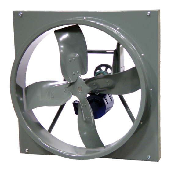
XLWH shown
Rotating Parts & Electrical Shock Hazard
Disconnect electric power before working on unit.
Follow proper lockout / tagout procedures to ensure
the unit cannot be energized while being installed or
serviced.
A disconnect switch should be placed near the fan
in order that the power can be swiftly cut off, in case
of an emergency and in order that maintenance
personnel are provided complete control of the
power source.
Grounding is required. All field-installed wiring
must be completed by qualified personnel. All field
installed wiring must comply with National Electric
Code (NFPA 70) and all applicable local codes.
Failure to follow these instructions could result in
death or serious injury.
Propeller Wall Fans
Installalation, Operation, And Maintenance Manual
• APD
• APB
• EWD
• EWB
• EPD
• EPB
• SWD
• SPB
• SPD
Exhaust & supply models
Carefully read this publication and any
supplemental documents prior to any
installation or maintenance procedure.
Loren Cook Company's Propeller Wall catalog provides
additional information describing the equipment, fan
performance, available accessories and specification data.
For information and instructions on special equipment,
contact Loren Cook Company.
For additional safety information, refer to AMCA
publication 410-96, Safety Practices for Users and
Installers of Industrial and Commercial Fans. This
document and all Cook publications may be obtained from
Cook by phoning (417) 869-6474, extension 166; by FAX
at (417) 832-9431; or by e-mail at info@LorenCook.com.
All Cook publications are available on LorenCook.com.
Receiving and Inspection
Carefully inspect the unit and accessories for any
damage and shortage immediately upon receipt of the unit.
• Turn the propeller by hand to ensure it turns freely and
does not bind.
• Record on the Delivery Receipt any visible sign of
damage.
Handling
Lift propeller wall fans by attachment to the power
assembly or by the shipping carton. Never lift by the shaft,
motor or housing.
Storage
If the fan is stored for any length of time prior
to installation, coat the shaft with grease or a rust
preventative compound. Store it in its original shipping
crate and protect it from dust, debris and the weather.
Rotate the wheel several revolutions every three to five
days to keep a coating of grease on all internal bearing
parts.
Installation
Fans mounted to a wall require a different wall opening
size than fans mounted in wall collars or wall housings. For
specific dimensions, refer to the submittal drawing for the
specific fan type.
Motor Installation
To prevent damage to the fan during shipping, motors 5
HP and larger, and extremely heavy motors (cast iron or
severe duty) are shipped loose and must be field mounted
by bolting the motor on the motor mounting plate in the
existing slots.
The motor should be mounted in order that the motor
plate is between the fan shaft and the motor shaft.
1.
Remove the motor plate mounting bolts and motor
plate.
1
Advertisement
Table of Contents

Related Manuals for COOK XWD


Summary of Contents for COOK XWD
-
Page 1: Motor Installation
• SPB Installers of Industrial and Commercial Fans. This • AWD • SPD document and all Cook publications may be obtained from • AWB Exhaust & supply models Cook by phoning (417) 869-6474, extension 166; by FAX at (417) 832-9431; or by e-mail at info@LorenCook.com. -
Page 2: Pulley Alignment
Remove the motor mounting bolts from the motor setscrew and by moving the motor pulley on the motor plate. shaft. Mount the motor to the motor plate aligning the The drawing below indicates where to measure the appropriate holes. allowable gap for the drive alignment tolerance. All Place the motor plate on the power assembly and contact points (indicated by WXYZ) are to have a gap reinstall the mounting bolts. - Page 3 Single Speed, Single Phase Motor 3 Phase, 9 Lead Motor Y-Connection 3 Phase, 9 Lead Motor Ground A Y-Connection Low Voltage High Voltage Line 208/230 Volts 460 Volts 4 5 6 4 5 6 7 8 9 Ground B When ground is required, attach to ground A or B with L 1 L 2 L 3 L 1 L 2 L 3 no.
-
Page 4: Operation
Shutters • Direction of rotation. • Excessive vibration. If your fan is supplied with a shutter, follow the direction • Unusual noise. below. If your fan is not supplied with a shutter, proceed • Bearing noise. to Final Installation Steps. •... -
Page 5: Motor Bearings
NLGI #2 consistency. If user desires to utilize another type Lubricants of lubricant, they take responsibility for flushing bearings Loren Cook Company uses petroleum lubricant in a and lines, and maintaining a lubricant that is compatible lithium base conforming to NLGI grade 2 consistency. -
Page 6: Bearing Replacement
Speed Increase XMW/ XMWH/ Maximum Maximum Close the pulley in order that the belt rides higher in the XMWHS XMWHS Size Size groove (larger pitch diameter). Ensure that the RPM limits of the fan and the horsepower limits of the motor are 1462 maintained. -
Page 7: Troubleshooting
inner ring face with a soft driver may be required. Do • Incorrect direction of rotation. Make sure the fan not hammer on the housing. rotates in same direction as the arrows on the motor The outer ring of the bearing is spherical and or belt drive assembly. - Page 8 Exhaust package fan with shutter guard Supply fan with wall collar, OSHA wire guard, motorized supply shutter & weather Illustrated is the typical installation of an exhaust PAC- Fan in a masonry wall with a shutter guard. The installer hood provides suitable fasteners (Hex bolts or Lag screws) to Illustrated is the typical installation of a supply wall fan support the fan.
-
Page 9: Parts List
Parts List XWD & SWD XPD & SPD Exhaust Exhaust Air Flow Flow Flow Rotation Supply XPHD Exhaust Size 20-24 Size 12-18 Air Flow Rotation Part Description Part Description Flow Flow Motor Stamped Aluminum Propeller Wire Guard Wall Collar Supply... - Page 10 XLW / XMW XLP / XLPH / XMP / XMPH Exhaust Exhaust Part Description Air Flow Base Prop Venturi Shaft Bearings (2) Air Flow Motor Rotation Supply Motor Plate Supply Air Flow Driven Sheave Drive Sheave Belt Mounting Collar Angles (4) Anchor Angles (2) Air Flow End Wire Guard...
- Page 11 Exhaust Exhaust Flow Air Flow Rotation Rotation Supply Supply Part Description Power Assembly Flow Prop Base Venturi Air Flow Rotation Motor Rotation Motor Plate Exhaust Wire Guard Exhaust Supply Air Flow Shaft Bearings Driver Sheave 15 14 15 14 Belt Driven Sheave Note: Since 2012, the venturi and base are...
- Page 12 Exhaust Rotation Exhuast Flow Supply Flow Supply Rotation Exhaust Rotation Exhuast Flow Supply Flow Supply Rotation Exhaust Supply 14 15 13 1 Flow Flow Exhaust Supply 14 15 14 15 Flow Flow Part Description Description Power Assembly Driver Sheave Prop Belt Base Driven Sheave...
- Page 13 Weather Hood Size 36 to 60 Weather Hood Size 8 to 30 Part Description Description Part Description Description Top Panel, Piece 1 Bird Screen Support Top Panel 1/2” Mesh Galvanized Bird Screen Top Panel, Piece 2 1/2” Mesh Galvanized Bird Screen Right Side Panel 1/4”...
- Page 14 Weather Hood EWB 72 Part Description Part Description Top Panel, Piece 1 Bottom Panel Top Panel, Piece 2 Bird Screen Support Right Side Panel Tip 1/2” Mesh Galvanized Bird Screen Right Side Panel 1/4” X 1/2” Speed Screw Left Side Panel Tip 5/16 SAE Steel Washer Left Side Panel...
-
Page 15: Limited Warranty
If you are entitled to warranty relief, a warranty adjustment will be completed within sixty (60) business days of the receipt of your written complaint by Loren Cook Company. This warranty gives only the original purchaser placing the fan in service specifically the right. - Page 16 Corporate Offices 2015 E. Dale Street Springfield, MO 65803 Phone 417-869-6474 Fax 417-862-3820 lorencook.com Propeller Wal IOM Manual - Oct 2012...
Need help?
Do you have a question about the XWD and is the answer not in the manual?
Questions and answers