Advertisement
Quick Links
®
This publication contains the installation, operation and
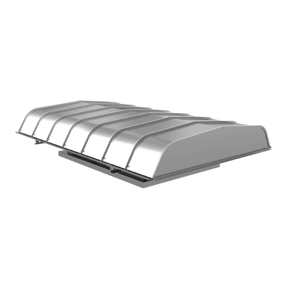
maintenance instructions for standard units of the GI/GR:
Gravity Ventilators.
Carefully read this publication and any
supplemental documents prior to any
installation or maintenance procedure.
Loren Cook catalog, Gravity Ventilation, provides addi-
tional information describing the equipment, unit perfor-
mance, available accessories and specification data.
For additional safety information, refer to AMCA Publica-
tion 410-96, Safety Practices for Users and Installers of
Industrial and Commercial Fans.
All of the publications listed above can be obtained from:
• lorencook.com
• info@lorencook.com
• 417-869-6474 ext. 166
For information and instructions on special equipment,
contact Loren Cook Company at 417-869-6474.
Receiving and Inspection
Immediately upon receipt of a GI/GR unit, carefully in-
spect it for damage and shortage.
• Check dampers (if supplied) for free operation of moving parts.
• Record on the Delivery Receipt any visible sign of damage.
Handling
Lift the unit by the lifting lugs (refer to Figure 4).
NOTICE! Never lift by the hood or end panels.
Storage
If the unit is stored for any length of time prior to installa-
tion, store it in its original shipping crate and protect it from
dust, debris and the weather.
Installation
Standard Units
Standard units not requiring knock down are shipped
fully assembled and ready for installation.
GI/GR IO&M
INSTALLATION, OPERATION AND MAINTENANCE MANUAL
The attachment of roof mounted fans to the roof curb as
well as the attachment of roof curbs to the building struc-
ture must exceed the structural requirements based on the
environmental loading derived from the applicable build-
ing code for the site. The local code official may require
variations from the recognized code based on local data.
The licensed engineer of record will be responsible for
prescribing the correct attachment based on construction
materials, code requirements and environmental effects
specific to the installation.
Failure to follow these instructions could result in death or
serious injury.
Knockdown Units
All knocked down units are factory pre-assembled and
then disassembled for shipping. Reassemble by aligning
holes and bolting together. Parts are marked as to allow
for ease of reassembly.
Reassembling the hood is best done from the under-
neath side. To work on the hood it is recommended to turn
the hood upside down on two wooden four by fours, this
will prevent it from rocking during assembly. Attach the
hood sections together by the overlapping joining seams
(see Figure 5). Make sure the upper sean is overlapping
the lower seam along their entire length. A slight tap with a
rubber mallet or dead blow hammer maybe required. Align
holes and use the provided section rail splice and bolts to
secure the hood section(s) together (see Figure 3).
For units with birdscreen, first completely assemble the
hood. Then fasten birdscreen securely to the inside of the
section rail, (see Figure 1), using speed screws (A) and
washer (B) stretching the birdscreen (C) as tight as pos-
sible. For units with aluminum birdscreen, the washers are
replaced with 1" aluminum strips at the factory. On units
with filters and birdscreen, the bird screen should extend
across the throat, not hindering the filter placement (see
Figure 4).
For units with a two piece mounting channel, insert the
mounting channel splice between the two pieces of the
mounting channel, aligning the holes (see Figure 3). Fas-
ten the three pieces of the mounting channel assembly to
the base using the bolts and nuts provided.
For units with multiple base sections: securely fasten the
base sections through the base section splice brackets
welded to the base sections using the bolts and nuts pro-
vided (see Figure 3). To eliminate the possible egress of
water through the base splices, caulking is recommended.
1
GI/GR
Gravity Vents
B51116-002
Advertisement

Related Manuals for COOK GI


Summary of Contents for COOK GI
- Page 1 Receiving and Inspection neath side. To work on the hood it is recommended to turn Immediately upon receipt of a GI/GR unit, carefully in- the hood upside down on two wooden four by fours, this spect it for damage and shortage.
- Page 2 (see Figure 4). GR units with less than a 73” throat length and GI units with less than a 61” throat length can be hinged. Hinging is accomplished by removing the bolts on one side and loosening the two bolts (refer to Figure 2) on the other side.
- Page 3 Section Rail Splice Mounting Channel Splice Base Splice Figure 4 Cross section of the end peice Cross section of the hood panel Hood Panel End Panel Base / Throat Hinged bolt Lifting lug Filter retaining clip Filter Mounting rail GI/GR IO&M B51116-002...
-
Page 4: Limited Warranty
Cook Company, General Offices, 2015 East Dale Street, Springfield, Missouri 65803-4637, explaining in writing, in detail, your complaint and referring to the specific model and serial numbers of your fan. Upon receipt by Loren Cook Company of your written complaint, you will be notified, within thirty (30) days of our receipt of your complaint, in writing, as to the manner in which your claim will be handled.
Need help?
Do you have a question about the GI and is the answer not in the manual?
Questions and answers