Table of Contents
Advertisement
Quick Links
®
This publication contains the installation, operation and
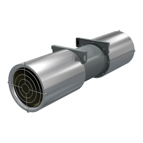
Maintenance instructions for standard unit of the JetStream
Tube Axial Fans/Jet Tunnel Fan.
Carefully read this publication and any
supplemental documents prior to any
Installation or maintenance procedure.
Loren Cook catalog, JetStream, provides additional infor-
mation describing the equipment, fan performance, available
accessories and specification data.
For additional safety information, refer to AMCA Publication
410-96, Safety Practices for Users and Installers of Industrial
and Commercial Fans.
All of the publications listed above can be obtained from:
• lorencook.com
• info@lorencook.com
• 417-869-6474 ext. 166
For information and instructions on special equipment, con-
tact Loren Cook Company at 417-869-6474.
Receiving and Inspection
Carefully inspect the fan and accessories for any dam-age
and shortage immediately upon receipt of the fan.
• Turn the propeller by hand to ensure it turns freely and does
not bind
• Record on the Delivery Receipt any visible sign of damage
Handling
Lift JetStream fans by placing a sling around the fan hous-
ing or through lifting eyes.
NOTICE! Never lift by the motor or inlet/outlet silencers.
Storage
If the fan is stored for any length of time prior to installa-
tion, rotate the propeller several revolutions every three to five
days. This keeps a coating of grease on all internal bearing
parts. Block propeller to prevent natural rotation and store it in
its original shipping crate and protect it from dust, debris and
weather.
JET STREAM IO&M
INSTALLATION, OPERATION AND MAINTENANCE MANUAL
JetStream
Rotating Parts & Electrical Shock Hazard:
Fans should be installed and serviced by qualified person-
nel only.
Disconnect electric power before working on unit (prior to re-
moval of guards or entry into access doors).
Follow proper lockout/tagout procedures to ensure the unit
cannot be energized while being installed or serviced.
A disconnect switch should be placed near the fan in order
that the power can be swiftly cut off, in case of an emergency
and in order that maintenance personnel are provided com-
plete control of the power source.
Grounding is required. All field-installed wiring must be com-
pleted by qualified personnel. All field installed wiring must
comply with National Electric Code (NFPA 70) and all ap-
plicable local codes. Ensure the power supply (voltage, fre-
quency and current carrying capacity of wires) is in accor-
dance with the motor nameplate.
Fans and blowers create pressure at the discharge and vac-
uum at the inlet. This may cause objects to get pulled into the
unit and objects to be propelled rapidly from the discharge.
The discharge should always be directed in a safe direction
and inlets should not be left unguarded. Any object pulled
into the inlet will become a projectile capable of causing se-
rious injury or death.
When air is allowed to move through a non-powered fan, the
impeller can rotate, which is referred to as windmilling. Wind-
milling will cause hazardous conditions due to unexpected
rotation of components. Impellers should be blocked in posi-
tion or air passages blocked to prevent draft when working
on fans.
Friction and power loss inside rotating components will
cause them to be a potential burn hazard. All components
should be approached with caution and/or allowed to cool
before contacting them for maintenance.
Under certain lighting conditions, rotating components may
appear stationary. Components should be verified to be sta-
tionary in a safe manner, before they come into contact with
personnel, tools or clothing.
Failure to follow these instructions could result in death or
serious injury.
The attachment of roof mounted fans to the roof curb as well
as the attachment of roof curbs to the building structure must
exceed the structural requirements based on the environ-
mental loading derived from the applicable building code for
the site. The local code official may require variations from
the recognized code based on local data. The licensed engi-
neer of record will be responsible for prescribing the correct
attachment based on construction materials, code require-
ments and environmental effects specific to the installation.
1
JetStream
Tube Axial Fans/Jet Tunnel Fan
P0000313-000
Advertisement
Table of Contents

Subscribe to Our Youtube Channel
Related Manuals for COOK JetStream


Summary of Contents for COOK JetStream
- Page 1 Handling rious injury or death. Lift JetStream fans by placing a sling around the fan hous- When air is allowed to move through a non-powered fan, the ing or through lifting eyes.
- Page 2 Installation Isolation Installation To help prevent vibration and noise from being transferred to the building, isolators are recommended. Floor Mounted Spring Isolators 1. Mount fan on isolation base or rails (if supplied). Ceiling Mounted Spring Isolator Rubber-in-Shear Ceiling Isolator 2. Elevate fan (or isolation base) to operating height and in- Figure 2 - Ceiling Mount Isolators sert blocks to hold in position.
- Page 3 Recommended Torque for Setscrews/Bolts (IN-LB) 2 Speed, 2 Winding, Single Phase Motor Setscrews Hold Down Bolts Ground A Recommended Key Hex High Speed Recommended Torque Size Across Size Torque Flats Min. Max. 5/64” 3/8”-16 Line 3/32” 1/2”-13 1/8” 5/8”-11 1440 Low Speed 5/16 5/32”...
- Page 4 Motor Services Should the motor prove defective within a one-year period, contact your local Loren Cook representative or your nearest authorized electric motor service representative. Motor Replacement 1. Remove the propeller side silencer to gain access to the motor.
- Page 5 • Cooling air diverted or blocked • Improper inlet clearance • Incorrect fan RPMs • Incorrect voltage Parts List JetStream Part Description Inlet/Outlet Guard Inlet/Outlet Silencer Housing Cast Aluminum...
- Page 6 (This page is intentionally left black) JET STREAM I0&M P0000313-000...
- Page 7 (This page is intentionally left black) JET STREAM IO&M P0000313-000...
- Page 8 2015 East Dale Street, Springfield, Missouri 65803-4637, explaining in writing, in detail, your complaint and referring to the specific model and serial numbers of your fan. Upon receipt by Loren Cook Company of your written complaint, you will be notified, within thirty (30) days of our receipt of your complaint, in writing, as to the manner in which your claim will be handled.
Need help?
Do you have a question about the JetStream and is the answer not in the manual?
Questions and answers