Advertisement
®
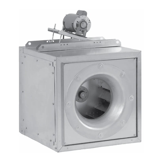
This publication contains the installation, operation and
maintenance instructions for standard units of the SQN:
Centrifugal Square Inline Fans.
Carefully read this publication and any
supplemental documents prior to any
installation or maintenance procedure.
Loren Cook catalog, SQN, provides additional informa-
tion describing the equipment, fan performance, available
accessories and specification data.
For additional safety information, refer to AMCA Publi-
cation 410-96, Safety Practices for Users and Installers of
Industrial and Commercial Fans.
All of the publications listed above can be obtained from:
• lorencook.com
• info@lorencook.com
• 417-869-6474 ext. 166
For information and instructions on special equipment,
contact Loren Cook Company at 417-869-6474.
Receiving
Inspection
Immediately, upon receipt of an SQN fan, carefully in-
spect the fan and accessories for damage and shortage.
• Turn the wheel by hand to ensure it turns freely and does
not bind.
• Inspect dampers for free operation of all moving parts
• Record on the Delivery Receipt any visible sign of damage.
Handling
Lift the fan by the lifting holes.
NOTICE! Never lift by the shaft, motor or housing.
Lifting Holes
SQN IO&M
INSTALLATION, OPERATION AND MAINTENANCE MANUAL
Lifting Holes
SQN-B
1
Centrifugal Square Inline Fans
Rotating Parts & Electrical Shock Hazard:
Fans should be installed and serviced by qualified person-
nel only.
Disconnect electric power before working on unit (prior to
removal of guards or entry into access doors).
Follow proper lockout/tagout procedures to ensure the unit
cannot be energized while being installed or serviced.
A disconnect switch should be placed near the fan in order
that the power can be swiftly cut off, in case of an emer-
gency and in order that maintenance personnel are pro-
vided complete control of the power source.
Grounding is required. All field-installed wiring must be
completed by qualified personnel. All field installed wiring
must comply with National Electric Code (NFPA 70) and all
applicable local codes.
Fans and blowers create pressure at the discharge and
vacuum at the inlet. This may cause objects to get pulled
into the unit and objects to be propelled rapidly from the
discharge. The discharge should always be directed in a
safe direction and inlets should not be left unguarded. Any
object pulled into the inlet will become a projectile capable
of causing serious injury or death.
When air is allowed to move through a non-powered fan,
the impeller can rotate, which is referred to as windmill-
ing. Windmilling will cause hazardous conditions due to
unexpected rotation of components. Impellers should be
blocked in position or air passages blocked to prevent draft
when working on fans.
Friction and power loss inside rotating components will
cause them to be a potential burn hazard. All components
should be approached with caution and/or allowed to cool
before contacting them for maintenance.
Under certain lighting conditions, rotating components
may appear stationary. Components should be verified to
be stationary in a safe manner, before they come into con-
tact with personnel, tools or clothing.
Failure to follow these instructions could result in death or
serious injury.
The attachment of roof mounted fans to the roof curb as
well as the attachment of roof curbs to the building struc-
ture must exceed the structural requirements based on the
environmental loading derived from the applicable build-
ing code for the site. The local code official may require
variations from the recognized code based on local data.
The licensed engineer of record will be responsible for pre-
scribing the correct attachment based on construction ma-
terials, code requirements and environmental effects spe-
cific to the installation.
SQN
B51141-004
Advertisement

Related Manuals for COOK SQN Series


Summary of Contents for COOK SQN Series
- Page 1 Disconnect electric power before working on unit (prior to Loren Cook catalog, SQN, provides additional informa- removal of guards or entry into access doors). tion describing the equipment, fan performance, available accessories and specification data.
-
Page 2: Belt
Storage 3 Phase, 9 Lead Motor Y-Connection To reverse, interchange any 2 line leads. If the fan is stored for any length of time prior to installa- Low Voltage High Voltage tion, completely fill the bearings with grease or moisture- 208/230 Volts 460 Volts inhibiting oil. -
Page 3: Motor Installation
SQI-D 70–90 Figure 1 White Line Black (High) Blue (Medium) Line Red (Low) NOTE: Insulate unused leads separately; leads are located at the motor inside the unit. WHITE Do not change the pulley pitch diameter to change ten- sion. This will result in a different fan speed. SQN-D 1. -
Page 4: Example
Rear discharge Side Discharge Duct block off planel Connection Collar NOTICE! Original Loren Cook Company labels must remain with the unit. This may require swapping ac- cess doors from one side to the other. Not on direct drive Not on direct drive Final Installation Steps 1. -
Page 5: B51141
Lubricants Inspect belt alignment and tension. Adjust and tighten as necessary. NOTICE! Loren Cook Company uses petroleum lubri- 24 Hour Interval cant in a lithium base. Other types of grease should not be used unless the bearings and lines have been Inspect belt tension. - Page 6 Typical Side Discharge Applications Side Access Bottom Access Bottom Access Example 1 Example 2 Example 3 Side Access Side Access Bottom Access Example 5 Example 6 Example 4 Side Access Side Access Side Access Example 9 Example 7 Example 8 Side Access Side Access Bottom Access...
- Page 7 Exxon Mobil Polyrex EM and Chevron SRI. Motor Services Should the motor prove defective within a one-year pe- riod, contact your local Loren Cook representative or your nearest authorized electric motor service representative. Bearing Cover Bearing Cover Screws...
-
Page 8: Bearing Support
Bearing Replacement fore initial start-up since rough handling during shipment could cause a shift in fan components. Refer to Wheel/ The fan bearings are pillow block ball bearings. Inlet drawing for correct overlap. 1. Loosen screws on bearing cover. Adjust the overlap by loosening the wheel hub and mov- 2. -
Page 9: Motor Support
Troubleshooting Parts Lists Problem and Potential Cause SQN-B/SQN-HP Low Capacity or Pressure: • Incorrect direction of rotation. Make sure the fan rotates in same direction as the arrows on the motor or belt drive assembly. • Poor fan inlet conditions. There should be a straight clear duct at the inlet. - Page 10 SQN-B/SQN-HP Side Discharge Airflow Description Part Sizes 60 - 165 Sizes 180 - 210 Sizes 225 - 402 L-Bolt (2) L-Bolt (2) L-Bolt (2) Motor Plate (1) Motor Plate (1) Motor Plate (1) Motor (1) Motor (1) Motor (1) Motor Support Bracket (2) Motor Support Bracket (2) Motor Support Bracket (2) Motor Support Rail (2)
- Page 11 SQN-D Airflow Part No. Description Motor Support Rail (2) Inlet Panel (1) Inlet Cone, Sizes 135 - 165 (1) Housing Frame Support (6) Housing Panel Motor Side (1) Access Panel (3) Motor Cover Back Plate (1) Cooling Tube (2) Electrical Box Electrical Conduit (1) Motor Plate Platform (1) Motor (1)
-
Page 12: Limited Warranty
Cook Company, General Offices, 2015 East Dale Street, Springfield, Missouri 65803-4637, explaining in writing, in detail, your complaint and referring to the specific model and serial numbers of your fan. Upon receipt by Loren Cook Company of your written complaint, you will be notified, within thirty (30) days of our receipt of your complaint, in writing, as to the manner in which your claim will be handled.
Need help?
Do you have a question about the SQN Series and is the answer not in the manual?
Questions and answers