Table of Contents
Advertisement
Quick Links
®
This publication contains the installation, operation and
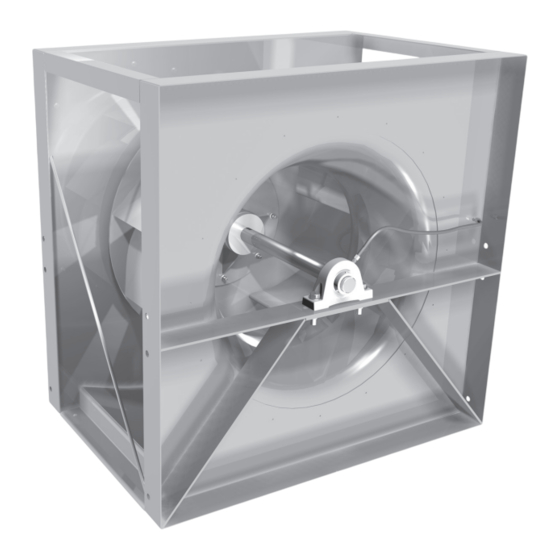
maintenance instructions for standard units of the PLC:
Centrifugal Plenum Fans.
Carefully read this publication and any
supplemental documents prior to any
installation or maintenance procedure.
Loren Cook catalog, PLC, provides additional informa-
tion describing the equipment, fan performance, available
accessories and specification data.
For additional safety information, refer to AMCA Publi-
cation 410-96, Safety Practices for Users and Installers of
Industrial and Commercial Fans.
All of the publications listed above can be obtained from:
• lorencook.com
• info@lorencook.com
• 417-869-6474 ext. 166
For information and instructions on special equipment,
contact Loren Cook Company at 417-869-6474.
Receiving and Inspection
Carefully inspect the fan and accessories for any dam-
age and shortage immediately upon receipt of the fan.
• Turn the wheel by hand to ensure it turns freely and does
not bind
• Inspect dampers (if supplied) for free operation of all mov-
ing parts
• Record on the Delivery Receipt any visible sign of damage
Handling
Lift the fan by the base or lifting eyes on the housing.
NOTICE! Never lift by the shaft, wheel or motor.
Storage
If the fan is stored for any length of time prior to installa-
tion, completely fill the bearings with grease or moisture-
inhibiting oil (refer to Lubrication, page 5). Rotate the fan
several revolutions every three to five days to keep a coat-
ing of grease on all internal bearing parts.
PLC
PLC IO&M
INSTALLATION, OPERATION AND MAINTENANCE MANUAL
Rotating Parts & Electrical Shock Hazard:
Fans should be installed and serviced by qualified person-
nel only.
Disconnect electric power before working on unit (prior to
removal of guards or entry into access doors).
Follow proper lockout/tagout procedures to ensure the unit
cannot be energized while being installed or serviced.
A disconnect switch should be placed near the fan in order
that the power can be swiftly cut off, in case of an emer-
gency and in order that maintenance personnel are pro-
vided complete control of the power source.
Grounding is required. All field-installed wiring must be
completed by qualified personnel. All field installed wiring
must comply with National Electric Code (NFPA 70) and all
applicable local codes. Ensure the power supply (voltage,
frequency and current carrying capacity of wires) is in ac-
cordance with the motor nameplate.
Fans and blowers create pressure at the discharge and
vacuum at the inlet. This may cause objects to get pulled
into the unit and objects to be propelled rapidly from the
discharge. The discharge should always be directed in a
safe direction and inlets should not be left unguarded. Any
object pulled into the inlet will become a projectile capable
of causing serious injury or death.
When air is allowed to move through a non-powered fan,
the impeller can rotate, which is referred to as windmill-
ing. Windmilling will cause hazardous conditions due to
unexpected rotation of components. Impellers should be
blocked in position or air passages blocked to prevent draft
when working on fans.
Friction and power loss inside rotating components will
cause them to be a potential burn hazard. All components
should be approached with caution and/or allowed to cool
before contacting them for maintenance.
Under certain lighting conditions, rotating components
may appear stationary. Components should be verified to
be stationary in a safe manner, before they come into con-
tact with personnel, tools or clothing.
Failure to follow these instructions could result in death or
serious injury.
The attachment of roof mounted fans to the roof curb as
well as the attachment of roof curbs to the building struc-
ture must exceed the structural requirements based on the
environmental loading derived from the applicable build-
ing code for the site. The local code official may require
variations from the recognized code based on local data.
The licensed engineer of record will be responsible for pre-
scribing the correct attachment based on construction ma-
terials, code requirements and environmental effects spe-
cific to the installation.
1
PLC
Centrifugal Plenum Fans
B51023-002
Advertisement
Table of Contents

Related Manuals for COOK PLC


Summary of Contents for COOK PLC
- Page 1 Centrifugal Plenum Fans INSTALLATION, OPERATION AND MAINTENANCE MANUAL ® This publication contains the installation, operation and maintenance instructions for standard units of the PLC: Centrifugal Plenum Fans. Rotating Parts & Electrical Shock Hazard: Carefully read this publication and any Fans should be installed and serviced by qualified person- supplemental documents prior to any nel only.
-
Page 2: Duct Installation
Isolation Figure 2 - Non-ducted Inlet Clearance Figure 2: Non-ducted Inlet Clearance* *Refer to the PLC catalog for discharge wall proximity factors. NOTICE! Although a certain amount of vibration is inherent in operating centrifugal fans, extreme vi- Wheel-to-Inlet Clearance... -
Page 3: Wiring Installation
L 1 L 2 L 3 L 1 L 2 L 3 that are not supplied by Loren Cook Company should have the recommendation of the motor manufacturer for use with a VFD. To reverse, interchange any two line leads. -
Page 4: Pulley Alignment
• Direction of rotation • Excessive vibration • Unusual noise Figure 3 • Bearing noise • Improper belt alignment or tension (listen for squealing) • Improper motor amperage or voltage PLC IO&M B51023-002... -
Page 5: Maintenance
(airborne abrasives) should be inspected ev- should be halved. ery three months. Loren Cook Company uses petroleum lubricant in a lithi- Regular inspections are recommended for fans exhaust- um base. Other types of grease should not be used unless ing non-contaminated air. -
Page 6: Bearing Replacement
Should the motor prove defective within a one-year pe- 11. Rotate the shaft to allow the bearing outer rings to find riod, contact your local Loren Cook representative or your their center of free movement. nearest authorized electric motor service representative. -
Page 7: Troubleshooting
Troubleshooting PLC Arrangement 3 Problem and Potential Cause Low Capacity or Pressure: • Incorrect direction of rotation. Make sure the fan rotates in same direction as the arrows on the motor or belt drive assembly • Poor fan inlet conditions. There should be a straight clear duct at the inlet •... -
Page 8: Limited Warranty
Cook Company, General Offices, 2015 East Dale Street, Springfield, Missouri 65803-4637, explaining in writing, in detail, your complaint and referring to the specific model and serial numbers of your fan. Upon receipt by Loren Cook Company of your written complaint, you will be notified, within thirty (30) days of our receipt of your complaint, in writing, as to the manner in which your claim will be handled.
Need help?
Do you have a question about the PLC and is the answer not in the manual?
Questions and answers