Table of Contents
Advertisement
Quick Links
Advertisement
Table of Contents
Troubleshooting

Related Manuals for Oriental motor BXSD30-C2


Summary of Contents for Oriental motor BXSD30-C2
- Page 1 Ⅱ Series USER MANUAL Thank you for purchasing an Oriental Motor product. This Manual describes product handling procedures and safety precautions. • Please read it thoroughly to ensure safe operation. • Always keep the manual where it is readily available.
- Page 2 How to read this manual This part explains the types and outlines of operating manuals, Entry the product overview, the name and function of each part and others. Installation and This part explains installation methods of the product and load, connection connection methods, and I/O signals.
-
Page 3: Table Of Contents
1 Entry 3.3 Connection diagram for each control mode.... 51 Explanation of I/O signals ........55 Introduction ..............8 4.1 Overview of I/O signals ............ 55 „ Input signals list ................55 1.1 Before using the product ...........8 „ Internal input circuit ..............55 1.2 Operating manuals for the product .......8 „... - Page 4 2.7 Position coordinate parameters ........97 „ Operation mode ..............118 „ Operation function, dwell time .......... 119 2.8 Analog adjustment parameters ........97 2.2 Starting method of positioning operation .....119 2.9 Common parameters............98 „ Operation data number selection mode ......119 2.10 I/O function parameters ..........
- Page 5 Setting the parameters .........154 Monitor ..............155 4.1 Status, I/O monitor ............155 4.2 Internal I/O monitor ............156 4.3 Alarm monitor ..............156 4.4 Warning monitor ..............157 4.5 Waveform monitor ............158 4.6 Test operation ..............159 4.7 I/O test ..................161 9 Inspection, troubleshooting and remedial actions Maintenance and inspection .......164 1.1 Inspection ................164...
- Page 6 −6−...
- Page 7 1 Entry This part explains the types and outlines of operating manuals, the product overview, the name and function of each part and others. Table of contents 1 Introduction............8 1.1 Before using the product .......... 8 1.2 Operating manuals for the product ...... 8 2 Safety precautions ..........
-
Page 8: Introduction
The product described in this document has been designed and manufactured to be incorporated in general industrial equipment. Do not use for any other purpose. Oriental Motor Co., Ltd. is not responsible for any compensation for damage caused through failure to observe this warning. -
Page 9: Safety Precautions
Safety precautions 2 Safety precautions The precautions described below are intended to ensure the safe and correct use of the product, and to prevent the user and other personnel from exposure to the risk of injury. Use the product only after carefully reading and fully understanding these instructions. - Page 10 Safety precautions CAUTION • Do not use the motor, gearhead, driver, or regeneration resistor in a state where the specification value is exceeded. Doing so may result in fire, electric shock, injury, or damage to equipment. • Do not insert an object into the openings in the driver. Doing so may result in fire, electrical shock, or injury. •...
-
Page 11: Precautions For Use
Precautions for use 3 Precautions for use This chapter covers limitations and requirements the user should consider when using the product. Be sure to match the output power of the driver with that of the motor when using. Wiring • Connect protective devices to the power line. Connect a circuit breaker or earth leakage breaker to the driver power line to protect the primary circuit. - Page 12 Precautions for use Insulation resistance measurement and dielectric strength test • Conduct the insulation resistance measurement or dielectric strength test separately on the motor and the driver. Conducting the insulation resistance measurement or dielectric strength test with the motor and driver connected may result in damage to the product.
-
Page 13: System Configuration
System configuration 4 System configuration Ⅱ The system configuration of the BX Series is shown below. • Setting of operation data and parameters Motor Data setter OPX-2A (sold separately) Driver PC in which the support software MEXE02 has been installed. Power supply Use the power supply voltage within the rated... -
Page 14: Preparation
Preparation 5 Preparation This chapter explains the items you should check, as well as the name and function of each part. 5.1 Checking the product Verify that the items listed below are included. Report any missing or damaged items to the branch or sales office from which you purchased the product. „... -
Page 15: Information About Nameplate
Preparation 5.2 Information about nameplate „ Motor Motor model Speci cations Serial number Manufacturing date „ Gearhead Gearhead model Manufacturing date Serial number „ Driver Driver model Speci cations Manufacturing date Serial number −15− 1 Entry... -
Page 16: Lists Of Combinations
Preparation 5.3 Lists of combinations Verify the model name of the purchased product against the model shown on the package label. Check the model name described on the nameplate of each product. • In the case of the electromagnetic brake type, the box ( „ ) in the model name indicates M. •... - Page 17 Preparation „ Round shaft type Driver Motor Cable Output Power supply voltage power Model Model Model Single-phase 100-120 VAC BXSD30-A2 30 W BXM230„-A2 Single-phase 200-240 VAC BXSD30-C2 Three-phase 200-240 VAC Single-phase 100-120 VAC BXSD60-A2 60 W BXM460„-A2 Single-phase 200-240 VAC BXSD60-C2 Three-phase 200-240 VAC CCSBF2...
-
Page 18: Names And Functions Of Parts
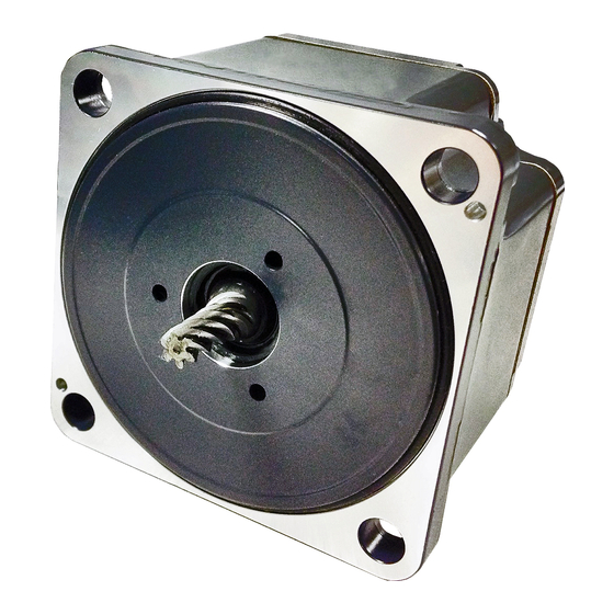
Preparation 5.4 Names and functions of parts This section explains the name and function for each part of products. „ Motor • Combination type-parallel shaft gearhead Standard type The figure shows a motor of 30 W, 60 W, or 120 W. Motor Gearhead Encoder... - Page 19 Preparation „ Driver Display Acceleration time potentiometer (ACC) Operation panel Operation keys Internal potentiometer (SPEED) Deceleration time potentiometer (DEC) Input signals connector (CN5) Encoder connector (CN4) Electromagnetic brake connector (CN3) CHARGE LED (Red) Data setter connector (CN6) Motor connector (CN2) Function setting switches (SW1) I/O signals connector (CN7) Regeneration resistor terminals (CN1)
- Page 20 −20− 1 Entry...
- Page 21 2 Installation and connection This part explains installation methods of the product and load, connection methods, and I/O signals. Table of contents 1 Installation ............22 2.9 Connecting the regeneration resistor ....44 2.10 Connection diagram (example) ......45 1.1 Installation location ..........22 2.11 Noise elimination measures ........48 1.2 Installing the combination type-parallel shaft gearhead...............22...
-
Page 22: Installation
Installation 1 Installation This chapter explains the installation locations and installation methods of the motor and driver, as well as how to install a load and analog external setting devices. 1.1 Installation location The motor and driver are designed and manufactured to be incorporated in equipment. Install them in a well-ventilated location that provides easy access for inspection. - Page 23 Installation „ Mounting hole dimensions [Unit: mm (in.)] Model ØA ØB ØD BXM230 70 (2.76) 24 (0.94) 10 (0.39) 4.5 (0.177) 94 (3.70) 34 (1.34) 13 (0.51) 6.5 (0.256) BXM460 BXM5120 104 (4.09) 40 (1.57) 18 (0.71) 8.5 (0.335) BXM6200 120 (4.72) 42 (1.65) 20 (0.79)
-
Page 24: Installing The Combination Type-Hollow Shaft Flat Gearhead
Installation 1.3 Installing the combination type-hollow shaft flat gearhead Do not install the motor to the mounting hole diagonally or assemble the motor forcibly. Note Doing so may cause damage to the flange pilot section, thereby resulting in damage to the motor. A combination type-hollow shaft flat gearhead can be installed by using either its front or rear side as the mounting surface. - Page 25 Installation „ Using the rear side as the mounting surface Hexagonal socket head screw • Mounting hole dimensions ØB or more 4×ØC Mounting plate Flat washer Spring washer Hexagonal nut∗ * Nuts are not included with the 200 W and 400 W types. Provide nuts separately or drill tapped holes in the mounting plate.
- Page 26 Installation „ Removing/Installing the gearhead See the following steps to replace the gearhead or to change the cable outlet position. Note that the motor cable cannot be positioned in the direction where it faces to the gearhead output shaft side. •...
-
Page 27: Installatin The Round Shaft Type
Installation 1.4 Installing the round shaft type Do not install the motor to the mounting hole diagonally or assemble the motor forcibly. Note Doing so may cause damage to the flange pilot section, thereby resulting in damage to the motor. Secure the product using hexagonal socket head screws (not included) through the four mounting holes. -
Page 28: Installing A Load For Combination Type-Parallel Shaft Gearhead, Round Shaft Type
Installation 1.5 Installing a load for combination type-parallel shaft gearhead, round shaft type When installing a load on the motor or the gearhead, align the center of the motor output shaft (gearhead output shaft) with the center of the load shaft. •... -
Page 29: Installation Of Load For Combination Type-Hollow Shaft Flat Gearhead
Installation 1.6 Installation of load for combination type-hollow shaft flat gearhead If the motor is subject to a strong impact upon instantaneous stop or receives a large overhung load, use a stepped load shaft. • Apply grease (molybdenum disulfide grease, etc.) on the surface of the load shaft and inner walls of the Note hollow output shaft to prevent seizure. - Page 30 Installation „ Non-stepped load shaft Install a spacer on the load shaft side and secure the retaining ring for hole to the load shaft by tightening the hexagonal socket head screw over a spacer, flat washer and spring washer. Spacer Retaining ring for hole Hexagonal socket head screw Spring washer...
-
Page 31: Permissible Radial Load And Permissible Axial Load
Installation 1.7 Permissible radial load and permissible axial load Make sure a radial load and axial load applied to the output shaft of the motor and gearhead will not exceed the permissible values shown in the table below. Failure due to fatigue may occur when the bearings and output shaft of the motor or gearhead are subject to Note repeated loading by a radial or axial load that is in excess of the permissible limit. -
Page 32: Installing The Driver
Installation 1.8 Installing the driver The driver is designed so that heat is dissipated via air convection and conduction through the enclosure. Install the driver in a state where clearances of at least 25 mm (0.98 in.) in the horizontal and vertical directions between the driver and enclosure or other equipment within the enclosure are provided. - Page 33 Installation „ Installation methods • Installation with screws Install the driver through the mounting holes using two screws (M4: not Mounting hole 30 mm (1.18 in.) included). (rear side) Mounting hole (rear side) • Installation to DIN rail When installing the driver to a DIN-rail, use the DIN rail mounting plate MADP02 (sold separately) and mount it to a 35 mm (1.38 in.) wide DIN rail.
-
Page 34: Installing The External Potentiometer (Sold Separately)
Installation 1.9 Installing the external potentiometer (sold separately) Install the external potentiometer PAVR-20KZ (sold separately) as shown in the figure. Variable resistor • Reference mounting hole dimensions [Unit: mm (in.)] Insulation sheet 7.5± (0.30± 0.02 Mounting plate Dial plate Ø3 (Ø0.12) Ø10 (Ø0.39) Set screw (M4) Tightening torque: 0.4 N·m... -
Page 35: Connection
Connection 2 Connection This chapter explains how to connect the motor, I/O signals and power supply to the driver, as well as grounding method. 2.1 Connection example A connection example shown below applies to the electromagnetic brake motor (200 W, 400W). Grounding Encoder cable Motor cable... -
Page 36: Connecting The Power Supply
Connection 2.2 Connecting the power supply Connect a power supply cable to the main power supply input terminals (CN1). A power supply cable is not included with the product. Provide a power supply cable separately. Manufacturer: PHOENIX CONTACT GmbH & Co. KG Model: FKC2,5/6-ST-5,08 Single-phase 100-120 VAC 50/60 Hz Single-phase 200-240 VAC 50/60 Hz... -
Page 37: Grounding
Connection 2.3 Grounding „ Grounding the motor Ground the Protective Earth Terminal of the motor at a position close to the motor. Wire it with the shortest distance. The grounding method varies depending on the motor output power. • 30 W, 60 W, 120 W Ground the motor using one of the four mounting holes on the motor frame. -
Page 38: Connecting The Motor And Driver
Connection 2.4 Connecting the motor and driver Connect the motor to the driver via the dedicated connection cable (sold separately) or flexible connection cable (sold separately). Connect the motor power connector of the connection cable to CN2, the electromagnetic brake connector to CN3, and the encoder connector to CN4. -
Page 39: Connecting The I/O Signals
Connection 2.6 Connecting the I/O signals Connect the input signals to CN5 and the analog external input signals and output signals to CN7. • Applicable lead wire: AWG26 to 20 (0.14 to 0.5 mm • Lead wire strip length: 8 mm (0.31 in.) Button of orange color 8 mm Insert the lead wire while pushing... - Page 40 Connection „ Input signals circuit All input signals of the driver are photocoupler inputs. Pin No. 6.6 kΩ When an external power supply is used: 24 VDC – 15 to +20%, 100 mA or more 820 Ω 2 to 10 Photocoupler „...
- Page 41 Connection „ Example of connection with I/O signal circuit • Sink logic circuit Programmable controller Driver 24 VDC IN-COM0 6.6 kΩ 820 Ω 820 Ω 6.6 kΩ 820 Ω 6.6 kΩ 6.6 kΩ 820 Ω 820 Ω 6.6 kΩ 820 Ω 6.6 kΩ...
- Page 42 Connection • Source logic circuit Programmable controller Driver 24 VDC IN-COM0 820 Ω 6.6 kΩ 820 Ω 6.6 kΩ 6.6 kΩ 820 Ω 820 Ω 6.6 kΩ 820 Ω 6.6 kΩ 6.6 kΩ 820 Ω 820 Ω 6.6 kΩ 820 Ω 6.6 kΩ...
-
Page 43: Connecting Analog External Setting Devices
Connection 2.7 Connecting analog external setting devices If the external potentiometer PAVR-20KZ (sold separately) or external DC voltage is connected to CN7, the analog setting for the operating speed or torque limit can be performed. Refer to p.104 to p.106 for how to set. „... -
Page 44: Connecting The Regeneration Resistor
Connection 2.9 Connecting the regeneration resistor If vertical drive (gravitational operation) such as elevator applications is performed or if sudden start-stop operation of a large inertia is repeated frequently, use the regeneration resistor EPRC-400P (sold separately) or RGB100 (sold separately). Install the regeneration resistor in a location where heat dissipation capacity equivalent to a level achieved with a heat sink [made of aluminum, 350×350×3 mm (13.78×13.78×0.12 in.)] is ensured. -
Page 45: Connection Diagram (Example)
Connection 2.10 Connection diagram (example) This section explains connection diagrams with the speed control mode (factory setting) as an example. When using the built-in power supply, set the switch SW1-4 SW1-4 to the ON side. It is set to the OFF side (use an external power ON: Built-in power supply) at the time of shipment. - Page 46 Connection Speed control mode Sink logic: When using an external power supply Setting of SW1 This is a connection example that the power supply is single-phase 100-120 VAC, the speed is set using an analog external setting device to operate the motor with sequence connection of SW1-4: OFF transistor type.
- Page 47 Connection Speed control mode Source logic: When using an external power supply Setting of SW1 This is a connection example that the power supply is single-phase 100-120 VAC, the speed is set using an analog external setting device to operate the motor with sequence connection of SW1-4: OFF transistor type.
-
Page 48: Noise Elimination Measures
Connection 2.11 Noise elimination measures There are two types of electrical noises: One is a noise to invade into the driver from the outside and cause the driver malfunction, and the other is a noise to emit from the driver and cause peripheral equipment malfunction. For the noise that is invaded from the outside, take measures to prevent the driver malfunction. -
Page 49: Connection Method For Each Control Mode
Connection method for each control mode 3 Connection method for each control mode Ⅱ Four control modes are provided in the BX Series. This section explains the assignment of I/O signals and connection method for each control mode. 3.1 Switching of control mode Ⅱ... -
Page 50: Assignment Of I/O Signals For Each Control Mode
Connection method for each control mode 3.2 Assignment of I/O signals for each control mode „ Speed control mode (factory setting) • CN5 • CN7 Pin No. Signal name Function Pin No. Signal name Function Input signals common IN-COM0 (for external power supply) Analog external setting input OUT0+ OUT0–... -
Page 51: X84; Bx-Compatible Mode (Position Control)
Connection method for each control mode „ BX-compatible mode (position control) • CN5 • CN7 Pin No. Signal name Function Pin No. Signal name Function Input signals common IN-COM0 (for external power supply) Analog external setting input START HOME-LS OUT0+ OUT0–... - Page 52 Connection method for each control mode Position control mode Sink logic: When using the built-in power supply Setting of SW1 This is a connection example that the power supply is single-phase 100-120 VAC, the torque limiting function is set using an analog external setting device to operate the motor with relays, SW1-4: ON switches and other contact switches.
- Page 53 Connection method for each control mode Position control mode Sink logic: When using an external power supply Setting of SW1 This is a connection example that the power supply is single-phase 100-120 VAC, the torque limiting function is set using an analog external setting device to operate the motor with SW1-4: OFF sequence connection of transistor type.
- Page 54 Connection method for each control mode Position control mode Source logic: When using the built-in power supply Setting of SW1 This is a connection example that the power supply is single-phase 100-120 VAC, the torque limiting function is set using an analog external setting device to operate the motor with SW1-4: OFF sequence connection of transistor type.
-
Page 55: Explanation Of I/O Signals
Explanation of I/O signals 4 Explanation of I/O signals Parameters described here can be set using any of the operation panel, MEXE02, or OPX-2A. 4.1 Overview of I/O signals Ⅱ With the BX Series, signals that can be assigned vary depending on the control mode. Refer to the following pages for details of signals. -
Page 56: Descriptions Of Input Signals
Explanation of I/O signals 4.2 Descriptions of input signals „ FWD input, RVS input • Speed control mode These are operation signals to rotate or stop the motor. When the operation data number is selected and the FWD input or the RVS input is turned ON, the motor rotates at the operating speed corresponding to the operation data number selected. - Page 57 Explanation of I/O signals „ FREE input • Speed control mode When the FREE input is turned ON, the motor current is cut off. If the "Operation selection after stopping" parameter (ID: 2069) is set to "1: Servo lock," the motor puts into an excitation state at motor standstill and generates the holding torque.
- Page 58 Explanation of I/O signals „ TH input The TH input is normally closed. When a regeneration resistor is used, connect the thermostat output of the regeneration resistor. The TH input is normally in the ON state and will be turned OFF if the thermostat of the regeneration resistor is activated, thereby causing an alarm of the regeneration resistor overheat to generate.
- Page 59 Explanation of I/O signals „ HOMES input (for position control mode only) This is a sensor input to connect the mechanical home in return-to-home operation. „ SSTART input (for position control mode only) This is a signal to start sequential positioning operation. Positioning operation based on the next operation data number is performed every time the SSTART input is turned ON.
-
Page 60: Overview Of I/O Signals
Explanation of I/O signals 4.3 Overview of I/O signals Ⅱ With the BX Series, signals that can be assigned vary depending on the control mode. Refer to the following pages for details of signals. „ Output signals list BX-compatible Signal name Speed control Position control Reference page... - Page 61 Explanation of I/O signals „ MOVE output The MOVE output is turned ON while the motor operates. Even when the motor cable is being pulled off, the MOVE output will be turned ON. „ READY output (for position control mode only) When the driver is ready to operate, the READY output is turned ON.
- Page 62 Explanation of I/O signals „ VA output When the detected speed reaches the “plus or minus range of speed attainment band with respect to the command speed, ” this output is turned ON. A range that the VA output is turned ON can be set using the "Attained speed output band" parameter (ID: 2215). If the parameter is set to 0, the VA output is not turned ON.
- Page 63 3 How to use the operation panel This part explains how to set data and how to operate a motor using the operation panel on the driver. Table of contents 1 Overview of the operation panel ....64 1.1 Names and functions of parts .......64 1.2 Function mode types ..........64 1.3 How to read the display ..........64 1.4 Edit lock function ............65...
-
Page 64: Overview Of The Operation Panel
Overview of the operation panel 1 Overview of the operation panel This chapter explains the name and function of each part of the operation panel as well as function modes. 1.1 Names and functions of parts The operation panel cannot be removed from the driver. Display Displays operation data or parameters... -
Page 65: Edit Lock Function
Overview of the operation panel 1.4 Edit lock function This is a function to prohibit the data editing or erasing by the operation panel. It is not allowed to change or delete data while the edit lock function is enabled. •... -
Page 66: Explanation Of The Function Mode (Speed Control Mode)
Explanation of the function mode (speed control mode) 2 Explanation of the function mode (speed control mode) 2.1 Screen transitions Monitor mode Speed Load factor Operation data number Alarms Control mode I/O monitor Warnings Data mode Data No.0 Data No.15 Operating speed Torque limit Acceleration time... -
Page 67: Monitor Mode
Explanation of the function mode (speed control mode) 2.2 Monitor mode This is a mode to be displayed when the power supply is turned on. The motor rotation speed is displayed at the factory setting. Use the monitor mode when operating the motor. Top screen of monitor mode Speed Warning... - Page 68 Explanation of the function mode (speed control mode) „ Speed The motor operating speed can be checked. The operating speed can also be displayed as the rotation speed of the gear output shaft. Set with the "Gear ratio" parameter (ID: 2085) and "Decimal place for gear ratio" parameter (ID: 2086). It is also possible to increase the rotation speed and display the increased speed.
-
Page 69: Data Mode
Explanation of the function mode (speed control mode) 2.3 Data mode This mode is used to set the operation data. Top screen of data mode Data No.0 Operating speed Setting (blinking) How to change the value Determine Increase the value (blinking) Decrease the value Determine the value... -
Page 70: Parameter Mode
Explanation of the function mode (speed control mode) 2.4 Parameter mode This mode is used to set the parameter. Top screen of parameter mode Parameter Present setting value ID input (blinking) (blinking) How to change the value Determine Increase the value (blinking) Decrease the value Initialization... -
Page 71: Test Mode
Explanation of the function mode (speed control mode) 2.5 Test mode The connection status of each I/O signal can be checked. Also, the operation can be checked only by connecting the motor and driver. Top screen of test mode I/O test JOG operation∗1 JOG operating speed Input signal... - Page 72 Explanation of the function mode (speed control mode) „ I/O test The ON-OFF status of each input signal can be checked and the ON-OFF status of each output signal can be switched. The voltage value input by the analog external setting device can also be checked. •...
- Page 73 Explanation of the function mode (speed control mode) Example of teaching function ∧ ∨ The motor rotates in the forward direction while the [ ] key is pressed. When decelerating the speed, press the [ ] key. ∨ If the [ ] key is pressed when the operating speed is 0 r/min, the motor rotates in the reverse direction and increases the ∧...
-
Page 74: Explanation Of The Function Mode (Position Control Mode)
Explanation of the function mode (Position control mode) 3 Explanation of the function mode (Position control mode) 3.1 Screen transitions Monitor mode Speed Position Load factor Operation data number Warning Alarm Selection number I/O monitor Control mode Speed Data mode Data No.0 Data No.15 Operation mode... -
Page 75: Monitor Mode
Explanation of the function mode (Position control mode) 3.2 Monitor mode This is a mode to be displayed when the power supply is turned on. The motor rotation speed is displayed at the factory setting. Use the monitor mode when operating the motor. Top screen of monitor mode Speed Last three digits of the present position... - Page 76 Explanation of the function mode (Position control mode) „ Speed The motor operating speed can be checked. The operating speed can also be displayed as the rotation speed of the gear output shaft. Set with the "Gear ratio" parameter (ID: 2085) and "Decimal place for gear ratio" parameter (ID: 2086). It is also possible to increase the rotation speed and display the increased speed.
- Page 77 Explanation of the function mode (Position control mode) „ I/O monitor The ON-OFF status of I/O signals for the driver can be checked. Each digit on the 7-segment LED display corresponds to a signal. The corresponding digit is lit when the signal is ON, and the digit is unlit when the signal is OFF.
-
Page 78: Data Mode
Explanation of the function mode (Position control mode) 3.3 Data mode This mode is used to set the operation data. Top screen of data mode Data No.0 Operation mode Setting (blinking) How to change the value Determine Increase the value (blinking) Decrease the value Setting of the rotation... - Page 79 Explanation of the function mode (Position control mode) „ Setting item In the case of the position control mode, all setting items other than the torque limit are set by the digital setting. When the torque limit is set by the analog setting, change the “Analog speed torque” parameter (ID: 2161) to “2: Torque. ” Item Description Setting range...
-
Page 80: Parameter Mode
Explanation of the function mode (Position control mode) 3.4 Parameter mode This mode is used to set the parameter. Top screen of parameter mode Parameter Present setting value ID input (blinking) (blinking) How to change the value Determine Increase the value (blinking) Decrease the value Initialization... -
Page 81: Test Mode
Explanation of the function mode (Position control mode) 3.5 Test mode The connection status of each I/O signal can be checked. Also, test operation of the motor or position preset can be performed. Top screen of test mode I/O test Data number selecting operation∗... - Page 82 Explanation of the function mode (Position control mode) „ I/O test The ON-OFF status of each input signal can be checked and the ON-OFF status of each output signal can be switched. The voltage value input by the analog external setting device can also be checked. •...
- Page 83 Explanation of the function mode (Position control mode) „ Teaching function ∧ ∨ The new position can be updated in the operation data by changing the travel amount of the motor with the [ keys. When pressing the [ ∧ ] key once, the motor rotates by one step in the forward direction.
- Page 84 −84− 3 How to use the operation panel...
- Page 85 4 Parameter list This part explains data and parameters that are required to operate a product. Table of contents 1 Operation data ............86 1.1 Speed control mode ..........86 „ Operation data types ............. 86 „ Operation data ID ............86 „...
-
Page 86: Operation Data
Operation data 1 Operation data The data described here can be set using any of the operation panel, MEXE02, or OPX-2A. Up to 16 operation data can be set (operaton data No.0 to No.15). 1.1 Speed control mode „ Operation data types The following operation data is required for speed control operation. -
Page 87: Position Control Mode
Operation data 1.2 Position control mode If the data is changed while the motor operates, a recalculation and setup will be performed after the operation is stopped, and the data will be updated. „ Operation data types The following data is required for positioning operation. Item Description Setting range... -
Page 88: X84; Note For Inputting The Value By The Operation Panel
Operation data „ Note for inputting the value by the operation panel Set in the following range when inputting the acceleration time, the deceleration time, or the dwell time because the operation panel can display 4-digit only. When setting less than one second 0.000 to 0.999 Setting range 0.000 to 30.000... -
Page 89: Parameter
Parameter 2 Parameter The parameters can be set using any of the operation panel, MEXE02, or OPX-2A. When writing parameters to the driver, they are saved in the non-volatile memory. The parameters saved in the non- volatile memory are stored even after the power supply is turned off. When a parameter is changed, the timing to update the new value varies depending on the parameter. - Page 90 Parameter Control mode *1 Reference Parameter name Setting range Initial value Speed Position page control control Positive software limit +8,388,607 –8,388,608 to +8,388,607 steps Negative software limit –8,388,608 The motor shaft rotates by 0.72° per one step. Preset position p.97 ×...
- Page 91 Parameter Control mode *1 Reference Parameter name Setting range Initial value Speed Position page control control 0: ×1 2086 Decimal place for gear ratio 1: ×0.1 p.93 2: ×0.01 2087 Multiplying gear 1 to 5 2113 Alarm initial drive 0: Disable 1: Enable 2129 Overload warning enable p.96...
-
Page 92: I/O Parameters
Parameter Control mode *1 Reference Parameter name Setting range Initial value Speed Position page control control 2258 Analog torque limit gain 0 to 250%/V 2259 Analog torque limit offset –50 to +50% Analog speed command 4000 p.97 2261 0 to 4000 r/min maximum value (3150) *2... -
Page 93: Operation Parameters
Parameter 2.3 Operation parameters All parameters can be set in both the speed control mode and position control mode. Parameters that can be used vary depending on the control mode. Control mode *2 Initial Update * 1 Parameter name Description Setting range Speed Position... -
Page 94: Motor Parameters
Parameter „ When displaying the conveyor transfer speed To display the conveyor transfer speed, set the conveyor speed reduction ratio using the formula below. Gearhead gear ratio Conveyor speed Conveyor transfer speed reduction ratio Feed rate per motor revolution Pulley diameter [m] × π Pulley diameter When the calculated conveyor speed reduction ratio is used, the conveyor transfer... - Page 95 Parameter „ Position loop gain, speed loop gain, speed loop integral time constant Vibration that occurs while the motor is accelerating/decelerating or at standstill can be adjusted to an optimal value. (The optimal value varies depending on the equipment or operating conditions.) Related parameters Adjusts the motor response in reaction to the position deviation.
-
Page 96: Alarm And Warning Parameters
Parameter 2.5 Alarm and warning parameters All parameters can be set in both the speed control mode and position control mode. Parameters that can be used vary depending on the control mode. Control mode *2 Initial Parameter name Description Setting range Update * 1 Speed Position... -
Page 97: Position Coordinate Parameters
Parameter 2.7 Position coordinate parameters All parameters can be set in both the speed control mode and position control mode. Parameters that can be used vary depending on the control mode. Control mode *2 Parameter name Description Setting range Initial value Update * 1 Speed Position control... -
Page 98: Common Parameters
Parameter 2.9 Common parameters All parameters can be set in both the speed control mode and position control mode. Parameters that can be used vary depending on the control mode. Control mode *2 Parameter Initial Description Setting range Update * 1 Speed Position name... -
Page 99: I/O Function Parameters
Parameter • Position control mode The operating speed is set by the digital setting. Note, however, that the torque limit can also be set by the analog setting. When the parameter is 0 When the parameter is 1 When the parameter is 2 Operation data Operating speed Torque limit... - Page 100 Parameter „ Setting range of the function selection parameter • IN input function selection parameter 0: Not used 7: –JOG 16: FREE 48: M0 1: FWD * 8: MS0 17: S-ON 49: M1 2: RVS * 9: MS1 18: STOP * 50: M2 3: HOME 10: MS2...
- Page 101 5 Operation in speed control mode This part explains how to operate in the speed control mode. Table of contents 1 Overview of speed control mode ....102 3 Operation ............109 3.1 Start operation and stop operation ....109 2 Setting the operation data ......
-
Page 102: Overview Of Speed Control Mode
Overview of speed control mode 1 Overview of speed control mode Operation 【Setting with operation data and parameters】 Speed control operation Speed setting method 【Analog setting】 【Digital setting】 Low speed Example: 600 r/min Internal potentiometer Operation panel High speed Example: 3000 r/min Driver External potentiometer Support software... -
Page 103: Setting The Operation Data
Setting the operation data 2 Setting the operation data 2.1 Operation data types Operation data can be set up to 16 data (operation data No.0 to No.15), and it is set using the analog setting or the digital setting. • Analog setting: Internal potentiometer (SPEED), PAVR-20KZ (sold separately), external DC voltage •... -
Page 104: X84; When Changing The Setting Method Of Acceleration Time And Deceleration Time
Setting the operation data „ When changing the setting method of acceleration time and deceleration time Use the "Analog acceleration deceleration" parameter (ID: 2162). When the parameter is 0 When the parameter is 1 Operation data Acceleration time Deceleration time Acceleration time Deceleration time No.0 Analog setting Analog setting... -
Page 105: X84; Setting By External Dc Voltage
Setting the operation data „ Setting by external DC voltage When using external DC voltage, set the "Analog speed torque" parameter • External DC voltage - Speed characteristics (representative values) (ID: 2161) to "1: Analog speed." Also, turn the M0 input ON. External DC 4000 power supply... -
Page 106: Setting The Torque Limit
Setting the operation data 2.5 Setting the torque limit The maximum output torque of the motor can be limited. Set when the motor torque is suppressed for safe uses or it is limited according to a load. Setting range: 0 to 250% This section explains how to set the torque limit by external DC voltage as an example. - Page 107 Setting the operation data • Related parameters Parameter name Description Setting range Initial value Sets the speed command per 1 VDC of the input 2256 Analog speed command gain 0 to 4000 r/min/V voltage by the analog external setting device. Sets the offset of the speed command input by 2257 Analog speed command offset –2000 to +2000 r/min...
-
Page 108: X84; Gain Adjustment And Offset Adjustment For Torque Limiting Value
Setting the operation data „ Gain adjustment and offset adjustment for torque limiting value Adjust using the following parameters. Torque limiting value Analog torque limit maximum value (ID : 2263) Analog torque limit Analog torque limit gain o set (ID: 2259) (ID: 2258) Setting voltage •... -
Page 109: Operation
Operation 3 Operation The motor operation can be started or stopped by inputting signals to control operation. 3.1 Start operation and stop operation „ Start operation When the FWD input is turned ON, the motor rotates in the forward direction. When it is turned OFF, the motor stops. When the RVS input is turned ON, the motor rotates in the reverse direction. -
Page 110: Rotation Direction
Operation 3.2 Rotation direction „ Rotation direction of the motor output shaft The rotation direction of the motor output shaft represents the direction when viewed from the motor output shaft. The rotation direction can be changed by the parameter. Related parameter Parameter name Description Setting range... -
Page 111: Example Of Operation Pattern
Operation 3.3 Example of operation pattern The figure below is an example when setting the internal potentiometer to 3000 r/min and external DC voltage to 1000 r/ min and switching the speed between these two levels. The rotation direction for the FWD input and RVS input shown here is the initial value of the "Motor rotation direction" parameter (ID: 450). -
Page 112: X84; When Using External Dc Voltage
Operation „ When using external DC voltage Connect the drivers as shown below. DC power supply Speed setting line 0 to 10 VDC Driver 1 Driver n Power supply input Power line Calculation method of current capacity (I) of external DC power supply when the number of drivers is n Current capacity (I) = 1 ×... -
Page 113: Multi-Speed Operation
Operation 3.5 Multi-speed operation When assigning the M0 to M3 inputs to the CN5 input terminals, the variable-speed operation of the motor can be performed using maximum 16 operation data. This section shows an example in which variable-speed operation is performed with eight operation data using the M0 to M2 inputs. - Page 114 −114− 5 Operation in speed control mode...
- Page 115 6 Operation in position control mode This part explains how to operate in the position control mode. Table of contents 1 Overview of position control mode ..116 5 Other operations ..........131 5.1 JOG operation ............131 2 Positioning operation ........118 5.2 Test operation ............
-
Page 116: Overview Of Position Control Mode
Overview of position control mode 1 Overview of position control mode Operation 【Setting with operation data and parameters】 Positioning operation Operation function • Single-motion operation • Linked-motion operation Speed Speed Operation Operation Operation Operation Operation method data No.0 data No.1 data No.0 data No.1 Time... - Page 117 Overview of position control mode When " " is displayed on the operation panel If the operation data number is checked immediately when the power supply is turned on in a state where the position control mode is set, " "...
-
Page 118: Positioning Operation
Positioning operation 2 Positioning operation This chapter explains positioning operation that is executed with setting the motor operating speed, position (travel amount), operation function, and other items to operation data. When positioning operation is executed, the motor starts rotating and accelerates until the operating speed is reached. Once it reaches the operating speed, the speed is maintained. -
Page 119: X84; Operation Function, Dwell Time
Positioning operation „ Operation function, dwell time There are the following three types in the operation function. Item Description Ref. Single-motion operation A single operation data set is used to execute positioning operation. p.122 Linked-motion operation Multiple sets of operation data are linked to execute multi-speed positioning operation. p.123 Dwell time refers to a waiting time at standstill between the present operation data and Linked-motion operation 2... -
Page 120: X84; Direct Positioning
Positioning operation „ Direct positioning When any of the MS0 to MS5 inputs is turned ON, positioning operation of the operation data number corresponding to the input signal is performed. Since positioning operation can be performed by turning any of the MS0 to MS5 inputs ON, the steps of selecting the operation data number can be saved. - Page 121 Positioning operation • Setting example Operation Sequential ①SSTART ②SSTART ③SSTART ④SSTART data positioning Operation data Operation data Operation data No.0 No.0 No.1 No.2 No.1 Enable No.2 No.3 Disable • Operating method 1) Check the READY output is being ON. 2) Turn the SSTART input ON. 3) The motor starts positioning operation.
-
Page 122: Operation Function
Positioning operation • Notes about sequential positioning operation If the following operations are performed while sequential positioning operation is executed, the starting point of the sequential positioning operation will be changed to the operation No.0. And the present operation data number will be set to "–1." •... -
Page 123: X84; Linked-Motion Operation
Positioning operation „ Linked-motion operation When the operation function of operation data is set to "Linked-motion," positioning operation based on the next data number is continuously executed without stopping the motor. If there is an operation data for which "Single-motion" is set, the motor will stop after the positioning operation with respect to the operation data of "Single-motion”... -
Page 124: X84; Linked-Motion Operation 2
Positioning operation „ Linked-motion operation 2 When the operation function of operation data is set to "Linked-motion 2," operation data whose rotation direction is different can be linked. In this case, the motor stops for the dwell time after each positioning operation is completed, and operates according to the next operation data. - Page 125 Positioning operation • Example of linked-motion operation 2: When combining the linked-motion operation and the linked-motion operation 2 Operation Operating Operation Operation Position Acceleration time Deceleration time Dwell time data speed mode function No.1 5000 Linked-motion 1.000 1.000 Not used No.2 10000 Linked-motion...
-
Page 126: Return-To-Home Operation
Return-to-home operation 3 Return-to-home operation This chapter explains return-to-home operation to set the position (home) that becomes the starting point when positioning operation is performed. Execute when returning the motor position to the home at the time of turning on the power supply or completing positioning operation. -
Page 127: Operation Image
Return-to-home operation 3.4 Operation image • Starting direction of return-to-home operation: • Starting direction of return-to-home operation: Positive direction Negative direction Home sensor Home sensor Positive Return-to-home 60 r/min∗ direction operation speed Positive Negative 60 r/min∗ 60 r/min∗ direction direction Negative 60 r/min∗... -
Page 128: Position Preset
Return-to-home operation 3.5 Position preset When the position preset is executed, the command position (present position) will be the value of the “Preset position" parameter (ID: 454). However, the preset will not be executed in the following conditions. • While the motor is operating •... -
Page 129: Continuous Operation
Continuous operation 4 Continuous operation When the FWD input or the RVS input is assigned, continuous operation can be executed. The motor operates continuously while the FWD input or the RVS input is being ON. For both the FWD and RVS inputs, the operation is performed at the operating speed of the operation data number being selected. - Page 130 Continuous operation • Operating method 1) Check the READY output is being ON. 2) Select the operation data number using the M0 to M3 inputs, and turn the FWD input ON. 3) The motor starts continuous operation. The READY output is turned OFF. 4) Turn the M0 input ON to select the operation data No.1.
-
Page 131: Other Operations
Other operations 5 Other operations 5.1 JOG operation If the +JOG input or the – JOG input is assigned, JOG operation can be performed. JOG operation is a function that executes positioning operation for the travel amount being set in the "JOG travel amount"... -
Page 132: Test Operation
Other operations 5.2 Test operation Test operation can be executed using any of the operation panel, MEXE02, or OPX-2A. JOG operation or teaching function can be executed in test operation. When executing using the operation panel, refer to p.81. When executing using the MEXE02, refer to the OPERATING MANUAL of the MEXE02. When executing using the OPX-2A, refer to the OPERATING MANUAL of the OPX-2A. -
Page 133: Stop Operation
Other operations 5.3 Stop operation „ STOP action Speed When the STOP input is turned ON while the motor is operating, the motor stops. The stopping method is determined by the setting of the "STOP input Motor movement action" parameter (ID: 256). Time For example, the operation when the "STOP input action"... -
Page 134: Wrap Function
Other operations 5.5 Wrap function This is a function that resets the command position and the multi-rotation data to 0 whenever the command position exceeds the value set in the "Wrap setting range" parameter (ID: 456). Since the multi-rotation data is also reset to 0, the continuous rotating operation in the same direction can be performed. - Page 135 Other operations Position Operation mode: Incremental Operation mode: Absolute 1000 ∆-250 +1000 3750 1250 3750 1250 ∆+1000 2250 2500 2500 ∆-2250 ∆-1000 4000 -1000 3750 1250 3750 1250 2500 2500 ∆+4750 1000 +6000 3750 1250 3750 1250 ∆+6000 2250 2500 2500 ∆-7250 ∆-6000...
- Page 136 −136− 6 Operation in position control mode...
- Page 137 7 BX -compatible mode Ⅱ The BX Series has the BX-compatible mode so that users can use it in almost the same connection as the traditional BX Series. This part explains about the BX-compatible mode. Table of contents 1 Descriptions of the BX-compatible mode ..............
-
Page 138: Descriptions Of The Bx-Compatible Mode
Descriptions of the BX-compatible mode 1 Descriptions of the BX -compatible mode 1.1 Switching of BX-compatible mode Switch the control mode to the BX-compatible mode before turning on the power supply. The setting will not Note be enabled if the control mode is switched after the power supply is turned on. „... -
Page 139: Assignment Of I/O Signals
Descriptions of the BX-compatible mode 1.3 Assignment of I/O signals „ BX-compatible mode (speed control) Ⅱ Series BX Series BX-compatible mode (speed control) Speed control mode Connector No. Pin No. Signal name Function Connector No. Pin No. Signal name Input signals common IN-COM0 (for external power supply) FREE... -
Page 140: X84; Bx-Compatible Mode (Position Control)
Descriptions of the BX-compatible mode „ BX-compatible mode (position control) Ⅱ Series BX Series BX-compatible mode (position control) Position control mode Connector No. Pin No. Signal name Function Connector No. Pin No. Signal name Input signals common IN-COM0 START (for external power supply) START HOME-LS HOME-LS... -
Page 141: Explanation Of I/O Signals
Explanation of I/O signals 2 Explanation of I/O signals This chapter explains I/O signals specific to the BX-compatible mode. 2.1 Input signals „ CW input, CCW input These signals are enabled in the BX-compatible mode (speed control). When the operation data number is selected and the CW input or the CCW input is turned ON, the motor rotates at the operating speed corresponding to the operation data number selected. -
Page 142: Output Signals
Explanation of I/O signals „ BRAKE input/ACL input The BRAKE input and the ACL input are normally closed. This signal is used as the BRAKE input in normal condition, but it functions as the ACL input if the driver protective function is activated. - Page 143 Explanation of I/O signals • BUSY output The BUSY output is turned ON during motor operation. It will be turned OFF when the operation is completed. When the motor has converged in a position of the "END signal range" parameter (ID: 259) against the command position, the BUSY output is turned OFF.
-
Page 144: Operation
Operation 3 Operation This chapter explains operations specific to the BX-compatible mode (position control). Extending the operation data, return-to-electrical home operation, and return-to-mechanical home operation in the BX- compatible mode are explained here. For other operations, refer to the next part. •... -
Page 145: X84; For Position Control
Operation „ For position control The operation data No.0 and No.1 can be changed to continuous operation using the "Compatible command - continuous operation" parameter (ID: 2289). Selecting the operation data No.6 makes return-to-electrical home operation, and selecting the operation data No.7 makes return-to-mechanical home operation. -
Page 146: Return-To-Mechanical Home Operation
Operation 3.3 Return-to-mechanical home operation This is an operation in which the reference point of positioning (mechanical home) is detected automatically. An external sensor is required. Select the operation data No.7 using the M0 to M2 inputs and turn the START input ON to start return-to-mechanical home operation. -
Page 147: Connection Example
Connection example 4 Connection example Ⅱ This chapter explains a connection example to replace the BX Series with the BX Series. BX-compatible mode (speed control): When the built-in power supply is used Setting of SW1 This is a connection example that the power supply is single-phase 100-120 VAC, the speed is set using an analog external setting device to operate the motor with relays, switches and other SW1-4: ON contact switches. - Page 148 Connection example BX-compatible mode (speed control): When an external power supply is used Setting of SW1 This is a connection example that the power supply is single-phase 100-120 VAC, the speed is set using an analog external setting device to operate the motor with sequence connection of SW1-4: OFF transistor type.
- Page 149 Connection example BX-compatible mode (position control): When the built-in power supply is used Setting of SW1 This is a connection example that the power supply is single-phase 100-120 VAC, the torque limiting function is set using an analog external setting device to operate the motor with relays, SW1-4: ON switches and other contact switches.
- Page 150 Connection example BX-compatible mode (position control): When the external power supply is used Setting of SW1 This is a connection example that the power supply is single-phase 100-120 VAC, the torque limiting function is set using an analog external setting device to operate the motor with SW1-4: OFF sequence connection of transistor type.
- Page 151 8 How to use MEXE02 This part explains how to set and edit parameters and data with the support software MEXE02. Table of contents 1 Starting MEXE02 ..........152 2 Setting the operation data ......153 3 Setting the parameters ........154 4 Monitor ..............
-
Page 152: Starting Mexe02
3) Turn on the driver power. 2. Set the communication port. 1) Click [Setting of the communication...] from the [Communication] menu. 2) Select “ORIENTAL MOTOR/Virtual COM Port” to click [OK]. 3. Select the product. 1) Click the [New] icon in the toolbar. Select “BX2. ”... -
Page 153: Setting The Operation Data
Setting the operation data 2 Setting the operation data Click “Operation data” in TreeView. The operation data edit window appears. „ Data entry The background color of a cell is initially white. When the value in the cell is changed, the color of the cell changes to yellow. -
Page 154: Setting The Parameters
Setting the parameters 3 Setting the parameters 1. The data edit window opens. 2. Click the parameter to be edited in TreeView. The parameter edit window appears. Refer to the operating manual of the MEXE02 for how to edit the data and others. 3. -
Page 155: Monitor
Monitor 4 Monitor The motor operating status, alarm condition, and I/O signals can be monitored. In the waveform monitor, the motor operating speed and I/O signal switching status can be checked in a waveform format. This section explains using the screen of the speed control mode as an example. 4.1 Status, I/O monitor Ⅱ... -
Page 156: Internal I/O Monitor
Monitor 4.2 Internal I/O monitor Ⅱ All I/O signals of the BX Series can be monitored. (Including signals not assigned to I/O) 1. Start the "Internal I/O monitor" using either of the following methods. Starting from the toolbar: Click the “Internal I/O monitor” icon Starting from the shortcut button: Click “Internal I/O monitor”... -
Page 157: Warning Monitor
Monitor 4.4 Warning monitor Ⅱ Warning information of the BX Series can be monitored. 1. Start the "Warning monitor" using either of the following methods. Starting from the toolbar: Click the [Warning monitor] icon Starting from the shortcut button: Click [Warning monitor] The window of the warning monitor appears. -
Page 158: Waveform Monitor
Monitor 4.5 Waveform monitor The motor speed or the status of I/O signals can be checked in a waveform format. 1. Start the "Waveform monitor" using either of the following methods. Starting from the toolbar: Click the [Waveform monitor] icon Starting from the shortcut button: Click [Waveform monitor] The window of the waveform monitor appears. -
Page 159: Test Operation
Monitor 3. Click "Run." Waveform measurement starts. 4. During measurement, click "Stop" to exit the waveform measurement. If "SINGLE" is selected for Mode in Trigger, measurement automatically ends when the waveform drawing ends. 5. To exit the waveform monitor, unselect "Start Waveform monitor." 4.6 Test operation „... - Page 160 Monitor • Position control mode 1. Start the "Teaching, remote operation" using either of the following methods. Starting from the toolbar: Click the “Teaching, remote operation” icon Starting from the shortcut button: Click “Teaching, remote operation” The window of the teaching, remote operation appears. 2.
-
Page 161: I/O Test
Monitor 4.7 I/O test The I/O signals of D-I/O can be tested. Input signals can be monitored, and output signals can forcibly be turned ON or OFF to check the connection with a host controller. 1. Start the "I/O test" using either of the following methods. Starting from the toolbar: Click the “I/O test”... - Page 162 −162− 8 How to use MEXE02...
- Page 163 9 Inspection, troubleshooting and remedial actions This part explains how to perform the periodical inspection and how to check and take remedial actions when a problem occurs. Table of contents 1 Maintenance and inspection ....... 164 1.1 Inspection ..............164 1.2 Warranty ..............
-
Page 164: Inspection, Troubleshooting And Remedial Actions
It is recommended that periodic inspections would be conducted for the items listed below after each operation of the motor. If an abnormal condition is noted, discontinue any use and contact your nearest Oriental Motor sales office. • Conduct the insulation resistance measurement or dielectric strength test separately on the motor and the Note driver. -
Page 165: Alarms, Warnings
Alarms, warnings 2 Alarms, warnings The driver provides alarms that are designed to protect the driver from overheating, poor connection, misoperation, etc. (protective functions), as well as warnings that are output before the corresponding alarms are generated (warning functions). 2.1 Alarms If an alarm is generated, the ALM output is turned OFF to stop the motor. -
Page 166: X84; Alarm Lists
Overcurrent the driver due to ground fault, etc. even when the power supply is turn off and on again, contact your nearest Oriental Motor sales office. possible • The power supply voltage exceeded • Check the voltage of the main approximately 120% of the rated power supply. - Page 167 Alarms, warnings Reset by Alarm Motor Alarm type Cause Remedial action the ALM- excitation *1 code RST input The main power supply was turned on Alarm initial drive *3 when an operation signal was being Turn the operation signal OFF. Possible •...
-
Page 168: Warnings
Alarms, warnings 2.2 Warnings If a warning is generated, the WNG output is turned ON. The motor will continue to operate. Once the cause of the warning is removed, the WNG output will be turned OFF automatically. „ Warning list Warning Warning type Cause... -
Page 169: Troubleshooting And Remedial Actions
During motor operation, the motor or driver may fail to function properly due to an improper speed setting or wiring. When the motor cannot be operated properly, refer to the contents provided in this chapter and take appropriate action. If the problem persists, contact your nearest Oriental Motor sales office. Phenomenon... - Page 170 −170− 9 Inspection, troubleshooting and remedial actions...
- Page 171 10 Appendix This part explains cables and peripheral equipment (sold separately) used in combination with the products in addition to the regulations and standards. Table of contents 1 Specifications ............ 172 1.1 Specifications ............172 1.2 General specifications ........... 173 2 Regulations and standards ......
-
Page 172: Specifications
Specifications 1 Specifications 1.1 Specifications The value in a state where the gearhead is not combined is described in each specification for the "rated torque," "maximum instantaneous torque, ” and "rated speed." Refer to “5.3 Lists of combinations” on p.16 for the motor model name. -
Page 173: General Specifications
Specifications • 400 W Motor BXM6400 Model Driver BXSD400-C2 Rated output power (Continuous) 400 W Single-phase 200-240 VAC Rated voltage Three-phase 200-240 VAC Permissible voltage range −15 to +10% Power Rated frequency 50/60 Hz supply input Permissible frequency range ±5% Single-phase: 4.7 A Rated input current Three-phase: 2.8 A... -
Page 174: Regulations And Standards
Regulations and standards 2 Regulations and standards This product is recognized by UL under the UL and CSA standards, and also affixed the CE Marking under the Low Voltage Directive and the EMC Directive. The product names that conform to relevant standards are the motor model names and driver model names. „... -
Page 175: Installing And Wiring In Compliance With Emc Directive
Installing and wiring in compliance with EMC Directive 3 Installing and wiring in compliance with EMC Directive Ⅱ The BX Series has been designed and manufactured to be incorporated in equipment. The EMC Directive requires that your mechanical equipment in which the product is installed satisfies the applicable requirements. The installation/wiring methods of the motor and driver explained here represent the basic methods that are effective in helping your mechanical equipment conform to the EMC Directive. - Page 176 • When extending the wiring distance between the motor and the driver, use the connection cable (for extension) which is sold separately. • The EMC testing is conducted using the Oriental Motor connection cable. „ Example of installation and wiring The figure shown below is the standard type.
-
Page 177: Cable And Peripheral Equipment (Sold Separately)
Cable and peripheral equipment (sold separately) 4 Cable and peripheral equipment (sold separately) „ Cable Required Connection cable or exible connection cable Driver Motor Connection cable (for extension) or exible connection cable (for extension) • Connection cable To connect a motor and a driver, always use the dedicated connection cable. Both connection cables and flexible connection cables are a set of two cables consisting a cable for motor and a cable for encoder. - Page 178 This is a set of a PC interface cable and USB cable. The cable is connected to the USB port on the PC. Model: CC05IF-USB [5 m (16.4 ft.)] The MEXE02 can be downloaded from Oriental Motor Website Download Page. You can check couplings and mounting brackets on the Oriental Motor Website. Visit our website for details. −178−...
- Page 179 Cable and peripheral equipment (sold separately) −179− 10 Appendix...
- Page 180 If a new copy is required to replace an original manual that has been damaged or lost, please contact your nearest Oriental Motor branch or sales office. • Oriental Motor shall not be liable whatsoever for any problems relating to industrial property rights arising from use of any information, circuit, equipment or device provided or referenced in this manual.
Need help?
Do you have a question about the BXSD30-C2 and is the answer not in the manual?
Questions and answers