Advertisement
Quick Links
O P E R A T I N G „ M A N U A L
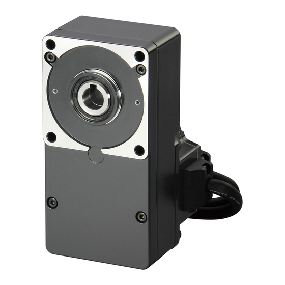
Brushless„Motor„and„Driver„Package
BXⅡ Series„
Introduction
„ „ Before„use
Only qualified and educated personnel should work with the product.
Use the product correctly after thoroughly reading the section
"Safety precautions".
The product described in this manual has been designed and
manufactured for use as a component to be installed in general
industrial equipment. Do not use for any other purpose. Oriental
Motor Co., Ltd. is not responsible for any damage caused through
failure to observe this warning.
„ „ Operating„Manuals„for„the„BXⅡ„Series
The following two types of operating manuals are provided for the
BXⅡ Series.
• • BXⅡ•Series•OPERATING•MANUAL•(this•document)
This manual explains the motor and driver functions as well as
installation method, and others.
• • BXⅡ•Series•USER•MANUAL
This manual explains the function, installation/connection method,
operating method of the motor and driver as well as detailed
information for using the product. The USER MANUAL does not
come with the product.
Check•the•USER•MANUAL•for•details•on•the•
For•details,•contact•your•nearest•Oriental•Motor•
sales•office•or•download•from•Oriental•Motor•
Website•Download•Page.
„ „ Standard„and„CE„Marking
This product is recognized by UL. The CE Marking (Low Voltage
Directive and EMC Directive) is affixed to the product in accordance
with EN Standards. Refer to p.20 for details.
HM-5141-7
product.•
Thank•you•for•purchasing•an•Oriental•Motor•product.
This•Operating•Manual•describes•product•handling•procedures•and•
safety•precautions.
• • Please•read•it•thoroughly•to•ensure•safe•operation.
• • Always•keep•the•manual•where•it•is•readily•available.
••••
Safety„precautions
The precautions described below are intended to prevent danger or
injury to the user and other personnel through safe, correct use of
the product. Use the product only after carefully reading and fully
understanding these instructions.
Warning
Caution
Note
General
• Do not use the product in explosive or corrosive environments, in
the presence of flammable gases, locations subjected to splashing
water, or near combustibles. Doing so may result in fire, electric
shock or injury.
• Only qualified and educated personnel should be allowed to
perform installation, connection, operation and inspection/
troubleshooting of the product. Handling by unqualified and
uneducated personnel may result in fire, electric shock, injury or
equipment damage.
• Do not transport, install, connect or inspect the product while the
power is supplied. Always turn the power off before carrying out
these operations. Failure to observe these instructions may result
in electric shock or malfunction.
• The terminals on the driver front panel marked with
indicate the presence of high voltage. Do not touch these terminals
while the power is on. Doing so may result in fire or electric
shock.
• Do not use a standard type motor (not equipped an electromagnetic
brake) in a vertical application. If the driver protective function
is activated, the motor will stop and the moving part of the
equipment may drop, thereby causing injury or equipment damage.
• Do not use the brake mechanism of the electromagnetic brake
motor as a safety brake. It is intended to hold the moving parts and
motor position. Using it as a safety brake may result in injury or
damage to equipment.
• If the driver protective function was activated, remove the cause
and reset the protective function. Continuing the operation without
removing the cause of the problem may result in malfunction of
the motor and driver, leading to injury or damage to equipment.
Installation
• The motor and driver are Class I equipment.
When installing the motor and driver, ground their Protective
Earth Terminals. Failure to do so may result in electric shock.
• Install the motor and driver inside an enclosure. Failure to do so
may result in electric shock or injury.
Handling•the•product•without•observing•the•
instructions•that•accompany•a•"Warning"•symbol•may•
result•in•serious•injury•or•death.
Handling•the•product•without•observing•the•
instructions•that•accompany•a•"Caution"•symbol•may•
result•in•injury•or•property•damage.
The•items•under•this•heading•contain•important•
handling•instructions•that•the•user•should•observe•to•
ensure•safe•use•of•the•product.
Warning
symbol
1
Advertisement

Related Manuals for Oriental motor BXSD200-C


Summarization of Contents
Introduction
Before Use
Guidelines for personnel and product usage before initial operation.
Operating Manuals for the BX II Series
Information on the two types of operating manuals provided for the BX II Series.
Safety Precautions
General Safety Precautions
Precautions for preventing danger or injury during product use.
Installation Safety Precautions
Safety measures to follow during product installation.
Connection Safety Precautions
Safety guidelines for connecting cables and components.
Operation Safety Precautions
Safety measures to adhere to during product operation.
Maintenance and Inspection Precautions
Safety steps for performing maintenance and inspection.
Repair, Disassembly, and Modification Precautions
Warnings against unauthorized repair, disassembly, or modification.
General Cautionary Notes
General cautionary points regarding product usage and environment.
Installation Cautionary Notes
Cautionary advice related to product installation.
Precautions for Use
Specific precautions to follow during the product's usage.
Preparation and Checking Product Contents
Steps for preparing and verifying product contents before use.
Product Combinations and Parts
Combinations of Motors and Drivers
Details on matching Oriental Motor drivers with various motor models.
Motor Components and Functions
Identification and description of motor parts and their functions.
Driver Components and Functions
Identification and description of driver components and their functions.
Installation Guidelines
Location for Installation
Criteria and conditions for selecting an installation location.
Installing Combination Type
Instructions for installing combination type motors/gearheads.
Removing and Installing Gearhead
Procedures for removing and installing gearheads.
Installing Round Shaft Type
Guidelines for installing the round shaft type motor.
Installing Load to Parallel/Round Shaft Gearhead
Methods for attaching loads to parallel and round shaft gearheads.
Installing Load to Hollow Shaft Flat Gearhead
Instructions for mounting loads onto hollow shaft flat gearheads.
Permissible Radial and Axial Load
Limits for radial and axial loads on the output shaft.
Installing the Driver
Recommendations and conditions for installing the driver unit.
Installation Methods for Driver
Methods for installing the driver via screws, DIN rail, or bracket.
Installing Regeneration Unit (Accessory)
Steps for installing the optional regeneration unit for heat dissipation.
Installing External Potentiometer (Accessory)
Guidance on installing the optional external potentiometer for control.
Connection Procedures
Connection Example for Electromagnetic Brake Motor
Diagram showing connection for electromagnetic brake motors.
Connecting Power Supply (CN1)
Instructions for connecting the main power supply to the driver.
Grounding Procedures
Guidelines for grounding the motor and the driver.
Connecting Motor (CN2, CN3, CN4)
Steps for connecting the motor, electromagnetic brake, and encoder.
Selecting Power Supply for Input Signals
Guidance on selecting the power source for input signals.
Connecting I/O Signals (CN5, CN7)
Instructions for connecting input and output signals to the driver.
CN5 Pin Assignment
Detailed pin assignments for the CN5 input signals connector.
CN7 Pin Assignment
Detailed pin assignments for the CN7 I/O signals connector.
Connecting Analog External Setter
Procedure for connecting an analog setter or external DC voltage.
Connecting Regeneration Unit (Accessory)
Instructions for connecting the regeneration unit to the driver.
Switching Control Modes
Speed Control Mode (Factory Setting)
Configuration for speed control mode using DIP switches.
Position Control Mode
Configuration for position control mode using DIP switches.
BX-Compatible Mode (Speed Control)
Setting for BX-compatible speed control mode.
BX-Compatible Mode (Position Control)
Setting for BX-compatible position control mode.
Connector Function Table
Summary of functions for CN5 and CN7 connectors in speed control.
BX-Compatible Mode (Position Control) Details
Further details on BX-compatible position control settings.
Motor Operation
Operation by Input Signals
Operating the motor using external input signals like FWD, RVS, STOP.
Setting the Operation Speed
Methods for setting motor speed using panel, setter, or external voltage.
Test Operation (JOG Operation)
Procedure for performing JOG operation to check connections and motor.
How to Read the Operation Panel
Name of Each Part for Operation Panel
Identification of components on the driver's operation panel.
Screen Transitions
Overview of screen navigation and modes on the operation panel.
Protective Functions and Alarms
Alarm List
List of driver alarms, their causes, and remedial actions.
Alarm List Continuation
Further details on alarms and their causes and remedial actions.
Warning List
List of driver warnings, their causes, and remedial actions.
Accessories and Compliance
Accessories (Sold Separately)
List of optional accessories like cables, potentiometers, and software.
Standard and CE Marking
Information on UL recognition, CE marking, and relevant directives.
UL Standards and CSA Standards
Details on UL and CSA standards applicable to the motor and driver.
Low Voltage Directives
Requirements and considerations for Low Voltage Directives.
EMC Directive Compliance
Information on EMC compliance and related standards.
Need help?
Do you have a question about the BXSD200-C and is the answer not in the manual?
Questions and answers