
Related Manuals for WEIHONG PM53C


Summarization of Contents
Preface
About This Manual
Introduces the manual's purpose, content structure, and target audience.
Applicable Product Models
Lists PM53B/53C control cards and their key features as described in the manual.
Contact Us
Provides company contact details for technical support, pre-sales, and after-sales services.
Precautions
Precautions Related to Storage and Transportation
Safety guidelines for transporting and storing the product to prevent damage or injury.
Precautions Related to Installation
Essential safety measures and requirements for installing the CNC system and its components.
Precautions Related to Wiring
Critical safety instructions and best practices for electrical wiring connections.
Precautions Related to Running & Debugging
Safety guidelines to follow before and during system operation and debugging.
Precautions in Use
Important considerations for the safe and effective operation of the CNC system.
Precautions Related to Product and Manual
Clarifies the relationship between this manual and manufacturer's guides.
Precautions When Opening the Package
Steps to verify product contents, check for damage, and report discrepancies.
1 Overview
PM53B/53C Motion Control Card
Structural drawing and interface details of the PM53B/53C motion control card.
2 Installation
2.1 Installation Steps
Step-by-step instructions for installing the CNC system hardware and software.
2.2 Manually Update the Hardware Driver
Procedure for manually updating the CNC system hardware driver via Device Manager.
2.3 Customized Installation Package
Utilizing NcHelper.exe to customize installation packages with specific parameter settings.
3 Wiring
3.1 Signal Types
Explanation of different input and output signal types used in the system.
3.1.1 Binary Input Signal
Details on connecting mechanical switches and photoelectric/proximity switches.
3.1.2 Relay Output Signal
Information on relay output contact points and load capacity.
3.1.3 Differential Output Signal
Description of pulse command format and differential signal output circuitry.
3.2 MPG Interfaces
Pin definition and connection details for Manual Pulse Generator (MPG).
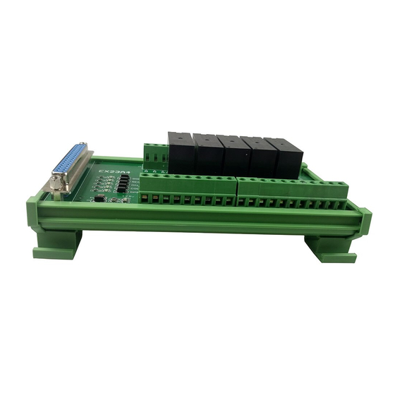
3.3 Wiring Diagram of Terminal Board
Wiring diagrams for EX23A and 6B-EX4A terminal boards.
3.4 Wiring Diagram of Terminal Board and Stepping Driver
Diagrams for connecting terminal boards to stepping drivers.
3.4.1 Connection to Stepping Driver with COM Port
Wiring configuration for stepping drivers using COM port.
3.4.2 Connection to Differential Input Stepping Driver
Wiring configuration for stepping drivers with differential input.
3.5 Wiring Diagram of Terminal Board and Servo Driver
Diagrams for connecting terminal boards to various servo drivers.
3.5.1 Wiring with WISE Servo Driver
Wiring diagram for connecting WISE servo drivers to the terminal board.
3.5.2 Wiring with YASKAWA Σ-II Servo Driver
Wiring diagram for connecting YASKAWA Σ-II servo drivers.
3.5.3 Wiring Diagram of DELTA ASDA_ A/AB Servo Driver
Wiring diagram for DELTA ASDA_A/AB servo drivers.
3.5.4 Wiring Diagram of PANASONIC MINAS_A5 Servo Driver
Wiring diagram for PANASONIC MINAS_A5 servo drivers.
3.5.5 Wiring Diagram of MITSUBISHI MR-E Servo Driver
Wiring diagram for MITSUBISHI MR-E servo drivers.
3.5.6 Wiring Diagram of FUJI FALDIC-ẞ Servo Driver
Wiring diagram for FUJI FALDIC-ẞ servo drivers.
3.5.7 Wiring Diagram of STONE GS Servo Driver
Wiring diagram for STONE GS servo drivers.
3.6 Parameter Setting of Servo Drivers
Guide to configuring parameters for various servo drivers.
3.6.1 Parameter Setting of WISE Servo Driver
Detailed parameter settings for WISE servo drivers.
3.6.2 Parameter Setting of YASKAWA Σ-II Servo Driver
Detailed parameter settings for YASKAWA Σ-II servo drivers.
3.6.3 Parameter Setting of DELTA ASDA_ A Servo Driver
Detailed parameter settings for DELTA ASDA_A servo drivers.
3.6.4 Parameter Setting of DELTA ASDA_B Servo Driver
Detailed parameter settings for DELTA ASDA_B servo drivers.
3.6.5 Parameter Setting of PANASONIC MINAS_A4 Servo Driver
Detailed parameter settings for PANASONIC MINAS_A4 servo drivers.
3.6.6 Parameter Setting of MITSUBISHI MR-E Servo Driver
Detailed parameter settings for MITSUBISHI MR-E servo drivers.
3.6.7 Parameter Setting of FUJI FALDIC-ẞ Servo Driver
Detailed parameter settings for FUJI FALDIC-ẞ servo drivers.
3.6.8 Parameter Setting of STONE GS Servo Driver
Detailed parameter settings for STONE GS servo drivers.
4 Machine Tool Debugging
4.1 Debugging Steps
Comprehensive guide covering the process of machine tool debugging.
4.2 Pulse Test
Method to detect and diagnose pulse loss issues in the machine tool.
5 Software License Agreement
Important-Read Carefully before Using This Product
Critical notice emphasizing careful review of the software license agreement.
Description of Further Rights and Restrictions
Defines the scope of rights and limitations for using the software product.
Intellectual Property Rights Notice
Statement on ownership and protection of intellectual property rights.
After-sales Guarantee
Details the warranty period and terms for the software carrier.
Limitation of Liability
Specifies the limits of the company's responsibility for damages.
Termination
Outlines the conditions for terminating the software license agreement.
Applicable Law
Identifies the legal framework governing the license agreement.
Need help?
Do you have a question about the PM53C and is the answer not in the manual?
Questions and answers