Table of Contents

Related Manuals for Amazone UX 6200 Super


Summarization of Contents
User Information
Purpose of the document
Explains the content and purpose of the operating manual for safe and efficient handling.
Locations in the operating manual
Explains how directions are specified within the manual, always in the direction of travel.
Diagrams
Explains how instructions, responses, and item numbers are presented in diagrams.
General safety instructions
Obligations and liability
Outlines the responsibilities of the operator and user regarding manual compliance and safety regulations.
Risks in handling the machine
Details potential risks to user, machine, and property when operating the machine improperly or in a faulty state.
Guarantee and liability
Explains exclusions for damage claims based on improper use, unauthorized changes, or external factors.
Representation of safety symbols
Explains the meaning of danger, warning, caution, important, and note symbols used in the manual.
Organisational measures
Lists necessary personal protective equipment and emphasizes keeping the operating manual accessible.
Safety and protection equipment
Stresses the importance of checking safety and protection equipment before each use for proper attachment and functionality.
Informal safety measures
Advises compliance with general national regulations for accident and environmental protection, plus road traffic rules.
User training
Specifies that only trained and instructed personnel may operate or maintain the machine, requiring supervision for trainees.
Safety measures in normal operation
Highlights the need for fully functional safety equipment and daily checks for damage and equipment function.
Danger from residual energy
Warns about residual mechanical, hydraulic, pneumatic, and electrical energy on the machine and advises informing personnel.
Maintenance and repair work, fault elimination
Details requirements for timely maintenance, securing media, fixing assemblies, checking bolted connections, and testing safety devices post-work.
Design changes
Prohibits unauthorized machine modifications and requires written approval for any expansion or modification work.
Spare and wear parts and aids
Emphasizes using genuine AMAZONE parts and warns against liability for damage caused by non-approved parts.
Cleaning and disposal
Advises careful handling and disposal of materials, especially during lubrication work and cleaning with solvents.
User workstation
States that the machine should only be operated by one person seated in the tractor's driver's seat.
Warning symbols and other signs on the machine
Keeps warning symbols clean and legible, explains structure (danger description/avoidance), and how to obtain replacements.
Positions of warning symbols and other labels
Illustrates the placement of various warning symbols on the machine through diagrams (Fig. 1 and Fig. 2).
Potential risks from not observing the safety instructions
Lists dangers to people, environment, machine, and warranty claims from non-compliance with safety information.
Safety-conscious working
Emphasizes adhering to national safety regulations, accident prevention instructions, and road traffic rules.
Safety information for users
Stresses national safety regulations, warning symbols, checking immediate area, no riding, and controlled driving.
General safety and accident prevention information
Stresses national safety regulations, warning symbols, checking immediate area, no riding, and controlled driving.
Coupling and uncoupling the machine
Details safe procedures for connecting and disconnecting the machine to the tractor, including weight limits and securing against rolling.
Machine transportation
Covers checks before moving, weight limits, turning corners, securing parts, lighting, and driving speed adjustments for safe transport.
Use of the machine
Outlines requirements before starting work, clothing, safety equipment, load limits, and forbidden standing areas.
Hydraulic system
Details safety precautions for the high-pressure hydraulic system, including connections, depressurization, hose maintenance, and fluid handling.
Electrical system
Provides safety guidelines for working on the electrical system, including battery disconnection, fuse usage, and electronic component considerations.
Universal joint shaft operation
Covers safe practices for PTO shaft installation, removal, use, and potential dangers like entanglement or injury from rotating parts.
Coupled machines
Advises observing permitted combinations, drawbar loads, and ensuring tractor has adequate steering and braking power.
Brake system
Outlines requirements for brake system adjustment and repair, emphasizing specialist work and safety checks.
Pneumatic braking system
Details steps for coupling and operating the pneumatic braking system, including pressure checks and draining the air reservoir.
Hydraulic brake system for export machines
Notes that hydraulic brake systems are prohibited in Germany and provides guidelines for brake fluid replacement.
Tyres
Covers safe practices for tyre repair, checking air pressure, and using specified tyre sets, requiring specialist work.
Field sprayer operation
Advises observing crop protection agent recommendations, opening pressurized lines, using genuine parts, and handling water sources for filling.
Cleaning, maintenance and repairs
Warns against entering the spray liquid tank, specifies specialist workshops for tank repairs, and outlines general conditions for maintenance and cleaning.
Loading and unloading
Loading and unloading with a tractor
Highlights risks if the tractor is unsuitable or the brake system is not connected, and ensures tractor meets power requirements.
Loading using a lifting crane
Details the 4 attachment points for lifting and warns about tank contents and lifting belt tensile strength.
Transport locks for hydraulic stand
Instructs to remove transport locks for the stand after unloading the machine.
Product description
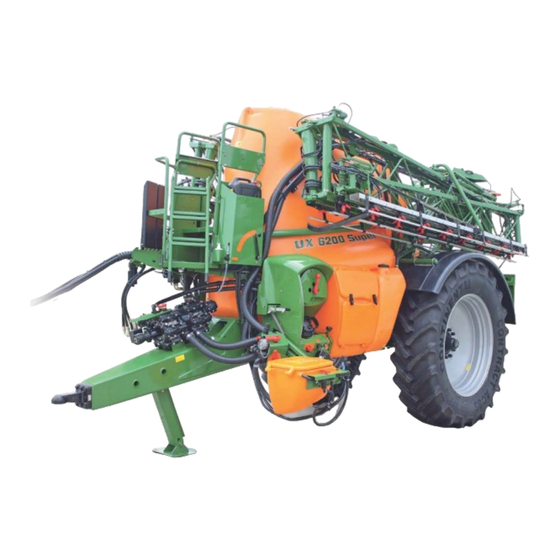
Overview of the assemblies
Provides a comprehensive overview of the machine's structure and identifies individual modules and controls with a diagram.
Safety and protection equipment
Illustrates transport locking mechanisms for booms, handrails on the maintenance platform, and PTO shaft guards.
Liquid circuit
Details the flow of spray liquid, flushing water, and fresh water through the machine's components using a circuit diagram.
Supply hoses between the tractor and the machine
Illustrates supply hoses in parking position: hydraulic lines, electric cable, machine cable, and brake lines.
Transportation equipment
Lists transportation equipment like rear lights, warning signs, reflectors, and registration plate holders with lighting.
Intended use
Defines the sprayer's purpose for crop protection and liquid fertiliser application, with restrictions for sloping terrain and user responsibilities.
Device inspections
Mentions EU regulations for device inspections and the need for regular checks by certified workshops, noting the inspection date on the plate.
Consequences of using certain crop protection agents
Warns about potential damage to machine parts from aggressive agents and unauthorized mixtures, recommending immediate cleaning.
Danger areas and danger points
Identifies areas around the machine where people can be caught, including moving parts, swivel ranges, and tanks with poisonous vapors.
Rating plate and CE mark
Lists information shown on the rating plate, such as vehicle ID, type, weight, and manufacturer details.
Conformity
States that the implement complies with specific EU directives like the Implement Directive and EMC Directive.
Maximum permissible application rate
Defines limitations on application rate due to agitator capacity and technical maximum rate, providing calculation formulas.
Technical Data
Total UX measurements including Super-S sprayer boom [mm]
Provides dimensions for UX models with Super-S booms in millimeters, including width and height ranges.
Total UX measurements including Super-L sprayer boom [mm]
Provides dimensions for UX models with Super-L booms in millimeters, including width and height ranges.
Data sheet
Presents technical specifications for UX models, including weight, volume, pressure, speed, and sprayer settings in a table format.
Weights basic machine and modules
Lists the weights of basic machines and various modules like axles, drawbars, and tyres for different UX Super models.
Sprayer boom weights
Provides weights for Super-S and Super-L sprayer booms based on working width.
Permissible total weight and tyres
Explains how total weight is determined by drawbar load, axle load, and tyre capacity, referencing relevant tables.
Permitted axle load
Details permitted axle loads for adjusting and fixed axles, including track width, load capacity, and brake system information.
Load capacity for each pair of wheels
Lists load capacities for various tyre sizes at different speeds and air pressures, crucial for determining total permissible weight.
Driving with reduced tyre pressure
Explains how tyre pressure affects load capacity and warns against selecting pressure lower than specified values.
Noise emissions data
States the workplace-related noise emission value and notes its dependence on the vehicle used.
Required tractor equipment
Lists necessary tractor specifications including engine power, electrical system, hydraulic system, brake connections, and PTO shaft requirements.
Construction and function of the basic machine
Functionality
Explains how the sprayer operates, including liquid flow, pump functions, filter use, and agitator operation.
Control terminal
Describes the central operation modes set via the control terminal and identifies its various control elements and functions.
PTO shaft
Explains the function of the wide angle PTO shaft for power transmission and highlights safety warnings related to its operation and installation.
Coupling the PTO shaft
Provides step-by-step instructions for safely coupling the PTO shaft, emphasizing clearance and securing measures.
Uncoupling the PTO shaft
Details the procedure for safely uncoupling the PTO shaft, including warnings about hot components and proper storage.
Hydraulic connections
Explains hydraulic hose line grips, colored markings, and tractor control unit usage for different functions like folding and lifting.
Coupling hydraulic hose lines
Provides instructions and warnings for correctly coupling hydraulic hose lines, emphasizing fluid compatibility and connector cleanliness.
Disconnecting hydraulic hose lines
Details the procedure for safely disconnecting hydraulic hose lines, including protecting plugs and sockets from dirt.
Air pressure brake system
Explains the dual-circuit pneumatic braking system, its components like the braking force regulator, air reservoir, and hose couplings.
Automatic load-dependent braking force regulator (ALB)
Describes how braking force is regulated by tank fill level via a float and warns against altering the adjustment measurement.
Coupling the brake system
Provides detailed steps for coupling dual-circuit and single-circuit pneumatic braking systems, including hose connection order and safety warnings.
Uncoupling the brake system
Outlines the procedure for uncoupling dual-circuit and single-circuit pneumatic braking systems, emphasizing the correct order of hose decoupling.
Hydraulic service brake system
States the tractor requires hydraulic braking equipment for control and outlines coupling/uncoupling procedures.
Emergency brake
Explains how the emergency brake functions to stop the machine when released from the tractor, detailing the pulling cable and brake valve.
Parking brake
Describes the parking brake's function, operation via crank, and how to adjust it for proper tension and cable slack.
Foldable wheel chocks
Explains how wheel chocks are attached and how to put them into operating position before uncoupling the machine.
Safety chain for implements without brake system
States that implements without or with single-line brakes require a safety chain, which must be fixed correctly to the tractor before transport.
Drawbars
Covers automatic trailer couplings, securing pins, straight drawbars, hitch drawbars, and drawbars for UniTrail steering systems, with safety warnings.
AutoTrail tracking control
Explains AutoTrail's function in precise tracking via drawbar angle, how it realigns steering axles, and its safety functions to prevent tipping.
AutoTrail steering drawbar
Details the use of the AutoTrail steering drawbar, its restrictions on slopes and reversing, and risks of machine tipping over.
AutoTrail steering axle
Explains the adjustment procedure for the steering axle on machines with specific track widths and tyre widths, ensuring collision avoidance.
Tracking control via tractor control unit
Describes how to manually steer the drawbar using the tractor control unit for precise tracking, especially on slopes, and mentions transport positioning.
Hydraulic stand
Explains the function of the hydraulically operated stand for supporting the uncoupled sprayer and its operation via a double-acting control valve.
Mechanic stand
Details the procedure for using the mechanic stand, including raising/lowering and securing it, with a warning about collision risk.
Spray liquid tank
Describes how the spray liquid tank is filled via different openings, its components like agitators and fill level indicators, and notes potential framework chafing.
Fill level indicator on the machine
Explains how the fill level indicator shows tank capacity, available electronically or mechanically.
Agitators
Describes the main and additional agitators, their function in mixing spray liquid, and how to adjust stirring performance.
Maintenance platform with ladder
Details the maintenance platform with a swivel-down ladder for reaching the filling dome, with warnings about poisonous vapors and risks of falling.
Suction port for filling the spray liquid tank (optional)
Illustrates the suction port for filling, including the suction hose, filter, and non-return valve.
Filling connection for filling the spray liquid tank with pressure (option)
Describes filling options with free flow, swivel spout, return flow, and automatic fill stop with a button.
Flushing water tank
Explains the function of the flushing water tank for thinning residues, cleaning the sprayer, and cleaning the suction chest, emphasizing the use of clear fresh water.
Hydropneumatic sprung suspension (optional)
Explains the suspension's automatic level regulation and manual mode functions, including reducing overhead clearance.
Pump equipment
Lists pump types and their technical data, including delivery capacity, power requirement, construction type, and drive methods.
Filter equipment
Emphasizes using and cleaning all provided filters for fault-free operation and paying attention to filter combinations and mesh sizes.
Filling sieve
Explains the function of the filling sieve in preventing spray liquid contamination during filling via the filling dome.
Suction filter
Describes the suction filter's role in filtering spray liquid during operation and water during filling, noting its mesh size.
Self cleaning pressure filter
Explains the self-cleaning pressure filter's function in preventing nozzle blockage and its various mesh inserts.
Nozzle filters
Details the function of nozzle filters in preventing nozzle blockage and lists different mesh sizes available for them.
Bottom sieve in the induction bowl
Describes the bottom sieve in the induction bowl and its purpose of preventing lumps and foreign bodies from being drawn in.
Drawbar (optional)
Covers the automatic drawbar's function for pulling braked trailers and mentions towing eye standards, with safety warnings about connection separation.
Transport and secure container (optional)
Describes the optional transport and secure container for storing protective clothing and accessories, with a warning about crushing risks during coupling.
Exterior wash down kit (optional)
Details the exterior wash down kit for cleaning the sprayer, including its hose, pressure hose, and spray gun, with warnings about accidental spraying.
Camera (optional)
Describes the optional camera feature, its viewing angle, heater/lotus coating, night-view technology, and backlight compensation.
Work floodlights
Mentions work floodlights on the sprayer boom and platform, and LED individual nozzle illumination with two power supply variants.
Comfort equipment
Details comfort equipment functions like remote-controlled cleaning, automatic agitator control, and filling stop via suction port, operated via the control terminal.
Control terminal
Explains tasks performed via the control terminal, including data input, sprayer control, boom operation, and monitoring.
AMASPRAY+
Describes AMASPRAY+ as a fully automatic control device for area-based regulation of spread rate based on speed and working width.
Construction and function of the sprayer boom
Super-S boom
Covers the Super-S boom's condition, suspension, and nozzle attachment, mentioning outer boom locking and swing compensation.
Swing compensation
Explains how swing compensation ensures even lateral distribution and how it is unlocked or locked for transport and folding.
Outer boom locking
Describes outer boom locking mechanisms that protect the boom from damage by moving around obstacles and returning it to working position.
Unlocking and locking the transport safety catch
Details the procedure for unlocking and locking the transport safety catch to secure the folded boom package during road transport.
Super-S boom, folding via the tractor control unit
Explains the Profi-folding and preselected folding procedures for the Super-S boom using tractor control units, including safety cautions.
Super-L boom
Describes the Super-L boom, its components like parallelogram frame and transport safety bow, and references outer boom locking and swing compensation.
Super-L boom, folded using tractor control unit
Details the Profi-folding and preselected folding operations for the Super-L boom using tractor control units, including safety cautions.
Working with the sprayer boom folded out on one side
Outlines permissible conditions for one-sided boom operation, emphasizing swing compensation locking and reduced speed, with warnings for Super-L and Super-S booms.
Reduction joint on the outer boom (optional)
Explains how the reduction joint manually folds the outer boom element to reduce working width, with instructions for nozzle changes and transport.
Boom width reduction (option)
Describes boom width reduction where one or two booms can remain folded, requiring activation of part width sections and stop taps for damping.
Boom extension (option)
Explains that the boom extension increases working width up to 1.20 meters and details its transport and working positions, including stop taps for outer nozzles.
Hydraulic tilt adjustment (optional)
Describes hydraulic tilt adjustment for aligning the boom parallel to the ground or target surface in difficult conditions, adjusted via control terminal or AMASPRAY+.
Distance control (optional)
Explains the Distance Control unit's function in automatically holding the boom at a set distance using ultrasound sensors, with automatic raising on headlands.
Spray lines and nozzles
Discusses fitting spray lines with single or multi nozzles based on conditions and provides a formula for calculating residue spraying distance.
Single nozzles
Details the components of a single nozzle body, including the diaphragm mechanism for preventing dripping and nozzle filters.
Multi nozzles (optional)
Recommends using multi nozzles for better performance, explaining how to rotate the head to select different nozzles and reduce working width.
Electric boundary nozzles (optional)
Explains how boundary nozzles can be switched off or on electrically from the tractor to extend coverage at the field edge.
Electric end nozzle switching (optional)
Describes switching off outer nozzles electrically near water sources for safety, up to three nozzles can be deactivated.
Electric additional nozzle switching (optional)
Details how additional nozzle switching engages an extra nozzle to increase working width by one meter.
Line filter for spray lines (optional)
Explains the purpose of line filters fitted in spray lines to prevent nozzle contamination and lists filter inserts.
Automatic single nozzle control (optional)
Covers separate control of 50 cm part width sections via electric single nozzle control for reduced overlap, including AmaSwitch and 4-way AmaSelect.
Special optional equipment for liquid fertiliser
Discusses liquid fertiliser types, conversion factors for spray rates, and the benefits of three-ray nozzles for root uptake, with operational areas listed.
7 hole nozzles / FD nozzles (optional)
Describes 7-hole and FD nozzles, their side-pointing outlets for large drops, and lists available models with their AUS spray rates.
Drag hose equipment for Super-S boom (optional)
Explains the drag hose unit with dosing discs for late top dressing, its numbered sections, and lists available dosing discs.
Drag hose equipment for Super-L boom (optional)
Details the drag hose equipment for Super-L booms, including hose placement, deflector hoops, spacing runners, and setting taps for different spray line usage.
Foam marker (optional)
Describes the foam marker's function in precise bout driving without tramlines, its adjustable bubble intervals, and its components like tank and compressor.
Pressure circulating system (DUS) (optional)
Explains the DUS system's role in constant liquid circulation for even spray patterns, reducing residue, and its principal components like switch taps and relief valves.
Lift module
Describes the optional lift module that raises the sprayer boom for increased nozzle height, actuated by the tractor control unit, with warnings about road driving and machine damage.
Commissioning
Checking the suitability of the tractor
Emphasizes checking tractor suitability before connecting, performing brake tests, and ensuring compliance with weight, axle load, and tyre capacity limits.
Calculating the actual values for the total tractor weight, tractor axle loads and tyre load capacities, as well as the minimum ballast
Explains that total tractor weight must exceed the sum of tractor empty weight, ballast, and connected machine weight.
Data required for the calculation
Lists required data for calculations, such as tractor empty weight, axle loads, drawbar load, and distances, referencing tractor documentation.
Calculation of the required minimum ballasting at the front GV min of the tractor for assurance of the steering capability
Provides the formula for calculating minimum front ballast needed for steering capability, referencing a table for values.
Calculation of the actual front axle load of the tractor TV tat
Gives the formula for calculating the actual front axle load and refers to the tractor manual for approved values.
Calculation of the actual total weight of the combined tractor and machine
Provides the formula for calculating the actual total weight of the tractor and machine combination.
Calculation of the actual rear axle load of the tractor TH tat
Offers the formula for calculating the actual rear axle load of the tractor.
Tyre load capacity
Instructs to enter double the approved load capacity for two tyres from manufacturer documentation for calculation.
Table
Provides a table for entering calculated and permissible values for ballast, total weight, axle loads, and tyre capacity, with warnings about exceeding limits.
Requirements for tractor operation with attached machines
Ensures proper combinations of connecting equipment and tractor capabilities, including drawbar load, axle loads, and tyre capacities.
Combination options for connection fittings and towing eyes
Shows permitted combinations for tractor connection fittings and towing eyes relative to maximum drawbar load.
Calculating the actual DC value for the combination to be coupled
Explains how to calculate the DC value for the tractor-machine combination to check connection fitting requirements.
Machines without their own brake system
Addresses risks from inadequate tractor braking power and specifies operational speed limits when the machine lacks its own brake system.
Adjusting the length of the PTO shaft to the tractor
Details how to adjust PTO shaft length for proper operation and warns about dangers from incorrect installation or design changes, recommending specialist checks.
Securing tractor / machine against accidental starting and rolling
Provides critical steps to prevent unintentional movement during interventions, including lowering the machine, shutting off the engine, and applying brakes/chocks.
Fitting wheels
Instructs on fitting wheels, including using specified tyre sets, checking nuts, and warnings about lifting and corrosion.
Initial operation of service brake system
Recommends performing brake tests when the sprayer is empty and loaded, and coordinating brakes with a specialist workshop.
Adjusting the hydraulic system with the system setting screw
Mentions adjusting the hydraulic system using the system setting screw, especially for Profi-folding.
AutoTrail position encoder
Explains the fitting of a holder for the AutoTrail position encoder on the tractor, its placement relative to the pivot point, and rod extension.
Track setting of the adjustable axle (workshop task)
Details how to adjust the implement's track width for alignment with tractor wheel tracks, including calculations and procedure for axle halves.
Coupling and uncoupling the machine
Coupling the machine
Provides warnings about operational risks and tractor suitability, emphasizing safe coupling practices and instructions about helpers.
Uncoupling the machine
Details the procedure for uncoupling the machine from the tractor, including securing against rolling, lowering the stand, and decoupling shafts and lines.
Manoeuvring the uncoupled machine
Explains how to manoeuvre an uncoupled machine, emphasizing careful shunting with the service brake released and the role of the manoeuvring vehicle.
Using the machine
Preparing for spraying operation
Emphasizes proper sprayer operation, filter use, thorough cleaning before agent changes, flushing nozzle lines, and filling water tanks.
Preparing the spray liquid
Details safe practices for preparing spray liquid, including using the induction bowl, safety regulations, avoiding contamination, and proper storage of agents.
Calculating the filling and refill quantity
Provides examples and formulas for calculating the required water and agent quantities to fill the tank and refill quantities for remaining spray areas.
Filling table for remaining spray area
Offers a table to calculate refill quantities for the spray liquid tank based on distance, working width, and spray rate.
Fill the spray liquid tank via the suction port and blend in the agent at the same time
Details the procedure for filling the tank using the suction port while blending agent, including switch tap operations and pump activation.
Adding the agent using ECO-Fill
Provides step-by-step instructions for adding agent using the ECO-Fill system, including pump activation, switch tap settings, and rinsing the counter.
Filling the spray liquid tank via the filling connection and blending in the agent (option)
Details the process for filling the tank using the filling connection, blending agents, adjusting pump speed, and operating suction chest and pressure gauge taps.
Spraying operation
Covers essential steps before spraying, including calibration, determining spray rate, adhering to it during operation, and selecting appropriate nozzles and speeds.
Applying the spray liquid
Emphasizes proper coupling, checking data on the control terminal, taking corrective action for fault messages, and managing spray pressure deviations.
Drift reduction measures
Provides measures to reduce drift, such as optimal timing, nozzle selection, spray pressure, boom height, and operational speed.
Dilute the spray liquid with flushing water
Details the procedure for diluting spray liquid with flushing water, involving pump activation, suction chest movement, and agitator control.
Residues
Classifies residues into excessive, technical, and final types, and provides guidelines for their disposal, emphasizing user protection and manufacturer instructions.
Diluting the excess residue in the spray liquid tank and spraying out the diluted residue remaining at the end of spraying operations
Outlines the process for diluting and spraying out excess residue, including switching off the sprayer, activating the pump, and managing diluted residues.
Emptying the spray liquid tank using the pump
Details the steps for emptying the spray liquid tank using the pump, involving connecting a drainage hose, adjusting switch taps, and switching off the agitator.
Cleaning the field sprayer
Advises minimizing exposure time, daily cleaning of utensils, thorough cleaning before agent changes, and cleaning on the field or in a courtyard with a collecting facility.
Cleaning the sprayer with the tank empty
Provides a threefold cleaning procedure for the sprayer with an empty tank, including pump activation, suction chest movement, and flushing agitators and spray lines.
Draining the final residues
Explains how to drain final residues on the field or in a courtyard, including collecting them and disposing of them according to legal guidelines.
Cleaning the suction filter when tank is empty
Details the daily cleaning procedure for the suction filter when the tank is empty, involving unscrewing the cover and cleaning with water.
Cleaning the suction filter when tank is full
Outlines the process for cleaning the suction filter when the tank is full, including pump activation, suction chest movement, and activating the relief valve.
Cleaning the pressure filter when the tank is empty
Describes cleaning the pressure filter when the tank is empty, involving undoing sleeve nuts and cleaning the filter with water.
Cleaning the pressure filter when the tank is full
Details cleaning the pressure filter when the tank is full, including moving the suction chest, draining residue, and cleaning the filter.
Exterior cleaning
Provides steps for exterior cleaning, including suction chest movement, opening switch taps, activating the pump, and cleaning with the spray gun.
Cleaning the sprayer during a critical agent change
Outlines the procedure for cleaning the sprayer during a critical agent change, involving multiple cleaning runs, flushing tanks, and cleaning filters.
Cleaning the sprayer with a full tank (work interruption)
Details how to clean the sprayer during a work interruption with a full tank, differentiating between nozzle control and without nozzle control methods.
Cleaning, maintenance and repair
Cleaning
Advises monitoring brake, air, and hydraulic lines, avoiding certain treatments, lubricating after cleaning, and observing handling regulations for cleaning agents.
Winter storage and long periods out of operation
Provides a comprehensive guide to preparing the machine for winter storage, including thorough cleaning, draining residues, and protecting components.
Lubrication specifications
Details lubrication requirements, grease nipple cleaning, lubrication points identified by foil, and lists recommended lubricants from different companies.
Lubrication point overview
Provides a detailed overview of lubrication points, their intervals in hours, number of points, and type of lubrication required, referencing figures.
Maintenance schedule – overview
Presents a maintenance schedule categorized by intervals (first working run, daily, weekly/50 hours), listing components, tasks, page references, and specialist workshop requirements.
Drawbars
Covers maintenance for drawbars, including danger warnings for damaged drawbars and prohibition of welding/drilling, plus lubrication and wear checks for yoke and hitch drawbars.
Axle and brake
Recommends balancing tractor and sprayer brakes, adjusting them according to EC directives, and performing general visual inspections of the brake system.
Automatic load-dependent brake force regulator (ALB)
Details how to check and set the brake pressure on the ALB via eye bolts for different container fill levels.
Parking brake
Explains how to readjust the parking brake if cables stretch or new pads are fitted, and how to adjust the cable slack when the brake is off.
Tyres / wheels
Covers wheel assembly procedures, checking wheel nuts, tyre pressure, using specified tyres, and requires specialist repair work.
Tyre pressures
Explains that required tyre pressure depends on size, load capacity, and speed, and how overloading or incorrect pressure reduces performance.
Fitting tyres
Advises removing rim corrosion before fitting new tyres, using new valves, and fitting valves with gasket inserts.
Hydropneumatic sprung suspension
Instructs to check screws for mechanical security and note specified tightening torques for the hydropneumatic suspension.
Drawbar
Instructs to check screws for mechanical security and note specified tightening torques for the drawbar.
Hydraulic system
Emphasizes specialist workshop work on the hydraulic system, depressurizing it, safe leak searching, and proper handling of hydraulic fluid with warnings about infection risk.
Labelling hydraulic hose lines
Explains information provided by valve chest identification on hydraulic hose lines, including manufacturer, date, and operating pressure.
Maintenance intervals
Lists maintenance intervals for checking hydraulic system tightness and hose lines for damage or leaks, both after initial use and on a regular basis.
Inspection criteria for hydraulic hose lines
For safety and pollution reduction, ensures hoses meet criteria for damage, brittleness, deformation, leaks, or installation compliance.
Installation and removal of hydraulic hose lines
Covers using genuine AMAZONE hoses, ensuring cleanliness, proper installation without tension, and avoiding scouring or exceeding bending radii.
Fluid filter
Details oil filters for Profi-folding and hydraulic pump drive, including contamination indicators and filter removal instructions.
Cleaning the solenoid valves
Explains how to flush solenoid valves to eliminate impurities, including unscrewing magnetic caps, removing solenoids, and cleaning valve rods.
Clean / exchange the filter in the hydraulic plug
Describes cleaning or exchanging the filter in the hydraulic plug if functions run slower, with warnings about escaping hydraulic oil.
Hydro-pneumatic pressure reservoir
Warns about injury when working on hydraulic systems with pressure reservoirs and outlines maintenance checks for precharge pressure and connections.
Adjusting the hydraulic throttle valve
Explains how factory-set operating speeds for hydraulic functions can be corrected using hexagon socket head screws on throttle valves.
Adjustments on the folded-out sprayer boom
Covers alignment adjustments for the sprayer boom (parallel and horizontal) and procedures for inner and outer boom sections.
Pump
Details checking and changing pump oil, ensuring correct oil level, and cleaning the pump after each use.
Checking the oil level
Instructs on checking the oil level using the mark, and topping up if necessary by removing the lid.
Changing the oil
Provides steps for changing pump oil, including pump removal, draining old oil, and filling with new oil.
Belt-driven pump
Covers checking and adjusting belt tension for belt-driven pumps and replacing worn drive belts.
Checking and replacing the suction and pressure-side valves
Advises paying attention to valve installation positions, ensuring valve guide integrity, and tightening nuts correctly for suction and pressure-side valves.
Checking and replacing the piston diaphragm
Recommends annual checks of piston diaphragms, paying attention to valve positions, and replacing all diaphragms if one is damaged.
Calibrate the flow meter
Refers to the ISOBUS operating manual for information on calibrating the flow meter.
Spray table
Spray tables for flat-fan, anti-drift, injector and airmix nozzles, spraying height 50 cm
Lists spray rates valid for water, with conversion factors for AUS and NP solutions, and guides nozzle type selection based on speed and characteristics.
Selecting the nozzle type
Explains how to determine nozzle type, size, spray pressure, and individual output using spray tables and working points.
Determining the nozzle type, nozzle size, spray pressure and individual nozzle output
Guides the user through determining nozzle type, size, spray pressure, and output using spray tables and example calculations.
Spray table for three-ray nozzle, spraying height 120 cm
Provides spray tables for three-ray nozzles (yellow and red) listing nozzle output and AUS spray rates based on pressure and speed.
Spray table for three-ray nozzles (blue)
Provides spray tables for three-ray nozzles (blue) listing nozzle output and AUS spray rates based on pressure and speed.
Spray table for three-ray nozzles (white)
Provides spray tables for three-ray nozzles (white) listing nozzle output and AUS spray rates based on pressure and speed.
Spray table for 7-hole nozzles
Lists spray tables for 7-hole nozzles (yellow, blue, red, brown) showing nozzle output and AUS spray rates based on pressure and speed.
Spray table for drag hose unit
Provides spray tables for drag hose units with different dosing discs, listing nozzle output and AUS spray rates based on pressure and speed.
Conversion table for spraying ammonium nitrate / urea solution (AUS) liquid fertiliser
Offers a conversion table for spraying AUS liquid fertiliser, relating N content and Sol. N values to water and AUS spray rates.
Need help?
Do you have a question about the UX 6200 Super and is the answer not in the manual?
Questions and answers