Table of Contents

Subscribe to Our Youtube Channel
Related Manuals for Amazone UF 1002


Summary of Contents for Amazone UF 1002
- Page 1 Operating Manual UF 1002 UF 1302 UF 1602 UF 2002 Mounted field sprayer with Comfort Package CP Please read this operating man- MG6980 ual before commissioning. BAG00225.3 09.22 Keep it in a safe place for Printed in Germany future use.
- Page 2 Reading the instruction Manual and following it should seem to be incon- venient superfluous enough to hear from others and to realize that a machine is good, to buy it and to believe that now everything should work by itself. The person in question would not only harm himself but also make the mistake of blaming the machine for pos- sible failures instead of himself.
- Page 3 H. DREYER SE & Co. KG Postfach 51 D-49202 Hasbergen, Germany Tel.: + 49 (0)5405 501-0 E-mail: amazone@amazone.de Spare part orders Spare parts lists are freely accessible in the spare parts portal at www.amazone.de. Please send orders to your AMAZONE dealer. UF02 BAG00225.3 09.22...
- Page 4 Foreword Formalities of the operating manual Document number: MG6980 Compilation date: 09.22 Copyright AMAZONEN-WERKE H. DREYER SE & Co. KG, 2022 All rights reserved. Reprinting, even of extracts, is only possible with the approval of AMAZONEN-WERKE H. DREYER SE & Co. KG. This operating manual is valid for all versions of the implement.
- Page 5 We update our operating manuals regularly. Your suggestions for im- provement help us to create ever more user-friendly manuals. AMAZONEN-WERKE H. DREYER SE & Co. KG Postfach 51 D-49202 Hasbergen, Germany Tel.: + 49 (0)5405 501-0 E-mail: amazone@amazone.de UF02 BAG00225.3 09.22...
-
Page 6: Table Of Contents
Table of Contents User Information ..................10 Purpose of the document ...................... 10 Locations in the operating manual ..................10 Diagrams ..........................10 General safety instructions ..............11 Obligations and liability ......................11 ... - Page 7 Table of Contents Function ..........................56 Control panel .......................... 57 5.2.1 Induction bowl with injector and canister flushing ..............62 5.2.2 Switch taps on the induction bowl ..................63 Parking supports ........................64 ...
- Page 8 Table of Contents Commissioning ..................115 Antifreeze in the spray liquid tank ..................115 Checking the suitability of the tractor .................. 116 7.2.1 Calculating the actual values for the total tractor weight, tractor axle loads and tyre load ...
- Page 9 Table of Contents 14.3 Lubrication instructions ......................187 14.4 Securing the raised boom ....................188 14.5 Maintenance schedule – overview ..................189 14.6 Hydraulic system ........................191 14.6.1 Labelling of hydraulic hose lines ..................192 ...
-
Page 10: User Information
User Information User Information The User Information section provides information on use of the oper- ating manual. Purpose of the document This operating manual describes the operation and maintenance of the machine. provides important information on safe and efficient handling of the machine. -
Page 11: General Safety Instructions
General safety instructions General safety instructions This section contains important information on safe operation of the machine. Obligations and liability Comply with the instructions in the operating manual Knowledge of the basic safety information and safety regulations is a basic requirement for safe handling and fault-free machine operation. Obligations of the operator The operator is obliged only to let those people work with/on the ma- chine who... - Page 12 General safety instructions Risks in handling the machine The machine has been constructed to the state-of-the art and the rec- ognised rules of safety. However, operating the machine may cause risks and restrictions to the health and safety of the user or third parties, ...
-
Page 13: Representation Of Safety Symbols
General safety instructions Representation of safety symbols Safety instructions are indicated by the triangular safety symbol and the highlighted signal word. The signal word (DANGER, WARNING, CAUTION) describes the gravity of the risk and has the following sig- nificance: DANGER Indicates an immediate high risk which will result in death or se- rious physical injury (loss of body parts or long term damage) if not avoided. -
Page 14: Organisational Measures
General safety instructions Organisational measures The operator must provide the necessary personal protective equip- ment as per the information provided by the manufacturer of the crop protection agent to be used, such as: Chemical-resistant gloves, Chemical-resistant overalls, Water-resistant footwear, ... -
Page 15: User Training
General safety instructions User training Only those people who have been trained and instructed may work with/on the machine. The operator must clearly specify the responsi- bilities of the people charged with operation and maintenance work. People being trained may only work with/on the machine under the supervision of an experienced person. -
Page 16: Safety Measures In Normal Operation
General safety instructions Safety measures in normal operation Only operate the machine if all the safety and protection equipment is fully functional. Check the machine at least once a day for visible damage and check the function of the safety and protection equipment. Danger from residual energy Note that there may be residual mechanical, hydraulic, pneumatic and electrical/electronic energy on the machine. -
Page 17: Spare And Wear Parts And Aids
Immediately replace any machine parts which are not in a perfect state. Only use genuine AMAZONE spare and wear parts or those approved by AMAZONEN-WERKE so that the type approval remains valid ac- cording to the national and international regulations. The use of spare... -
Page 18: Warning Symbols And Other Signs On The Machine
General safety instructions 2.13 Warning symbols and other signs on the machine Always keep all the warning symbols on the machine clean and in a legible state. Replace illegible warning symbols. You can obtain the warning symbols from your dealer using the order number (e.g. MD 075). -
Page 19: Positions Of Warning Symbols And Other Labels
General safety instructions 2.13.1 Positions of warning symbols and other labels Warning symbols The following diagrams show the arrangement of the warning symbols on the machine. UF02 BAG00225.3 09.22... - Page 20 General safety instructions Super-S- boom UF02 BAG00225.3 09.22...
- Page 21 General safety instructions Q-Plus-boom UF02 BAG00225.3 09.22...
- Page 22 General safety instructions Order number and explanation Warning symbols MD 078 Risk of crushing fingers or hands due to ac- cessible moving parts in the machine. This danger can cause extremely serious injuries and the loss of body parts. Never reach into the danger area when the trac- tor engine is running with PTO shaft / hydraulic / electronics system connected.
- Page 23 General safety instructions MD 086 Risk of crushing the entire body due to nec- essary periods spent under raised, unse- cured machine parts. This danger can cause extremely serious and potentially fatal injuries. Before spending time in the danger area under- neath raised machine parts, secure the raised parts to prevent them being accidentally lowered.
- Page 24 General safety instructions MD 097 Risk of crushing the entire body due to standing in the stroke area of the three-point suspension when the three-point hydraulics are actuated. This danger can cause extremely serious and potentially fatal injuries. Personnel are prohibited from entering the stroke area of the three-point suspension when the three-point hydraulics are actu- ated.
- Page 25 General safety instructions MD 108 Risk of explosion, or danger from hydraulic fluid escaping under high pressure, caused by the pressure accumulator which is under pressure from gas and oil. These dangers can cause serious and potentially fatal injuries if highly pressurised, escaping hy- draulic fluid penetrates the skin and passes into the body.
- Page 26 General safety instructions MD 173 Risk of breathing in hazardous materials via poisonous vapours from the spray liquid tank. This danger can cause extremely serious and potentially fatal injuries. Never climb into the spray liquid tank. MD 192 Danger of fluids escaping under high pres- sure while working on hoses and connec- tions under pressure! This can result in extremely serious injuries...
- Page 27 General safety instructions MD 212 Danger from escaping high-pressure hydrau- lic fluid due to leaking hydraulic hose lines. This danger may cause serious injuries, perhaps even resulting in death, if escaping high-pressure hydraulic fluid passes through the skin and into the body.
- Page 28 General safety instructions Danger from insufficient stability of the un- hitched field sprayer attachment due to im- proper uncoupling. These dangers can cause extremely serious and potentially fatal injuries. Before uncoupling the field sprayer attachment, always pull the parking supports out of their transport position into the parking position.
-
Page 29: Dangers If The Safety Information Is Not Observed
General safety instructions 2.14 Dangers if the safety information is not observed Non-compliance with the safety information can pose both a danger to people and also to the environment and machine. can lead to the loss of all warranty claims. In particular, non-compliance with the safety information could pose the following risks: ... -
Page 30: Safety Information For Users
General safety instructions 2.16 Safety information for users WARNING Risk of crushing, cutting, catching, being drawn in or impacts from inadequate roadworthiness and operational safety. Before starting up the machine and the tractor, always check their roadworthiness and operational safety. 2.16.1 General safety and accident prevention information ... - Page 31 General safety instructions When coupling and uncoupling machines, move the support equipment (if available) to the appropriate position (stability). When actuating the support equipment, there is a risk of injury from crushing and cutting points. Be particularly careful when coupling the machine to the tractor or uncoupling it from the tractor.
- Page 32 General safety instructions Machine transportation Comply with the national road traffic regulations when using pub- lic highways. Before moving off, check: the correct connection of the supply lines the lighting system for damage, function and cleanliness ...
-
Page 33: Hydraulic System
Replace the hydraulic hose lines if they are damaged or worn. Only use gen- uine AMAZONE hydraulic hose lines. The hydraulic hose lines should not be used for longer than six years, including any storage time of maximum two years. -
Page 34: Electrical System
General safety instructions 2.16.3 Electrical system When working on the electrical system, always disconnect the battery (negative terminal). Only use the prescribed fuses. If fuses are used that are too highly rated, the electrical system will be destroyed – risk of fire. ... - Page 35 General safety instructions Observe the prescribed pipe overlaps in transport and opera- tional positions. (Read and follow the operating manual from the PTO shaft manufacturer.) When turning corners, observe the permitted bending and dis- placement of the PTO shaft. ...
-
Page 36: Field Sprayer Operation
General safety instructions 2.16.5 Field sprayer operation Comply with the recommendations provided by the manufacturer of the crop protection product with regard to personal protective equipment warnings concerning the handling of crop protection pro- ducts regulations on dosing, applications and cleaning ... - Page 37 Do not fill field sprayers with water from bodies of water which are open to the public, for the protection of people, animals and the environment. Fill the field sprayer only using original AMAZONE filling devices! UF02 BAG00225.3 09.22...
-
Page 38: Cleaning, Maintenance And Repairs
Spare parts must meet at least the specified technical require- ments of AMAZONEN-WERKE. This is ensured through the use of genuine AMAZONE spare parts. When repairing field sprayers which have been used for liquid fertiliser application with ammonium nitrate / urea solution, ob-... -
Page 39: Loading And Unloading
Loading and unloading Loading and unloading Loading using a lifting crane The machine has two attachment points. Danger When loading the machine using a lifting crane, use the marked attach- ment points for lifting belts. Danger The minimum tensile strength of each lifting belt must be 1500 kg! UF02 BAG00225.3 09.22... -
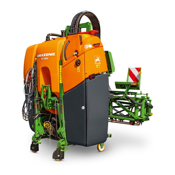
Page 40: Product Description
Product description Product description Overview of the assemblies (1) Spray liquid tank (10) Sprayer and agitator pump (2) Inspection hatch of the spray liquid tank for (11) Flushing water pump visual inspection (12) Parking position for hook tool of the parking (3) Spray liquid tank fill level indicator supports (4) Operating valve chest with cover... - Page 41 Product description (1) Folding sprayer boom (2) Part width section fittings (3) Shelf for the suction hose (4) Outer rinsing unit (5) Rear camera UF02 BAG00225.3 09.22...
-
Page 42: Safety And Protection Equipment
Product description Safety and protection equipment Left and right-hand parking supports to pre- vent the machine from falling over when parked Transport locking mechanism to prevent the Super-S boom from folding out unintention- ally (1) Visual check of the Super-S boom lock (1) Transport locking mechanism to prevent the Q-plus boom from folding out unintention- ally... -
Page 43: Supply Hoses Between The Tractor And The Machine
Product description Supply hoses between the tractor and the machine Supply hoses in parking position: (1) Hydraulic hose lines (depending on equip- ment provided) (2) Cable with connection for lighting (3) Computer cable with machine connector Transportation equipment Rear lighting (1) Rear lights, brake lights, turn indicators (re- quired if the turn indicators on the tractor are obscured) -
Page 44: Intended Use
Compliance with all the instructions in this operating manual. Execution of inspection and maintenance work. Exclusive use of genuine AMAZONE spare parts. Other uses to those specified above are forbidden and shall be con- sidered as improper. For any damage resulting from improper use: ... -
Page 45: Device Inspections
These are resistant to solvent-containing crop pro- tection agents. However their service life is reduced by use at low temperatures (e.g. AUS in frosty conditions). The materials and components used in the construction of AMAZONE field sprayers are safe for liquid fertiliser. UF02 BAG00225.3 09.22... -
Page 46: Danger Areas And Danger Points
Product description Danger areas and danger points The danger area is the area around the machine in which people can be caught by: work movements made by the machine and its tools materials or foreign bodies thrown out of the machine ... -
Page 47: Rating Plate
Product description Rating plate Machine rating plate (1) Implement number (2) Vehicle identification number (3) Product (4) Permissible technical implement weight (5) Tare weight kg (6) Model year (7) Year of manufacture 4.10 Conformity Directives/Standards designation The implement complies 2006/42/EC Implement directive with the... -
Page 48: Maximum Permissible Application Rate
Product description 4.12 Maximum permissible application rate The permissible application rate of the implement is limited by the minimum required agitator capacity. The agitator capacity per minute should be 5% of the hopper volume. This is particularly applicable for active substances that are hard to keep in suspension. -
Page 49: Technical Data
Product description 4.13 Technical Data 4.13.1 Basic machine Type UF 1002 UF 1302 UF 1602 UF 2002 Spray liquid tank Actual volume 1100 l 1400 l 1680 l 2125 l Nominal volume 1000 l 1300 l 1600 l 2000 l... -
Page 50: Spraying Technology
Product description Q-Plus sprayer boom Working width [m] 12.5 Transport width 2560 mm 2560 mm 2998 mm Overall length 850 mm Height of the parked implement 2800 mm Nozzle height from / to 500 mm / 2100 mm 4.13.2 Spraying technology Part-width sections depending on the working width Super-S1-sprayer boom Working width Number... - Page 51 Product description Super-S2-sprayer boom Working width Number Number of spraying nozzles width sections 6-6-6-6-6 15 m 3-5-5-4-5-5-3 16 m 7-6-6-6-7 6-8-8-8-6 5-6-5-4-5-6-5 18 m 2-3-6-5-4-5-6-3-2 8-8-8-8-8 5-5-6-8-6-5-5 20 m 3-4-6-5-4-5-6-4-3 9-8-8-8-9 6-6-6-6-6-6-6 21 m 4-4-6-5-4-5-6-4-4 4-4-3-3-5-4-5-3-3-4-4 6-6-6-6-6-6-6 21/15 m 6-4-4-5-4-5-4-4-6 3-3-4-4-5-4-5-4-4-3-3 9-10-10-10-9 6-6-8-8-8-6-6...
-
Page 52: Technical Residue
Product description Technical data: pump equipment Flushing Spraying / agitating water 160l/min 150 l/min 200 l/min 250 l/min 300 l/min Pump type EX 6500-C BPS160 BPS200 BPS260 BPS300 (0 bar) 162 l/min 199 l/min 249 l/min 299 l/min 55 l/min Delivery capacity (1060 rpm) at 540 rpm... - Page 53 Product description Technische Restmenge Gestänge Part-width section control Single nozzle control Work- Number Without DUS With DUS With DUS pro of part- width width sec- tions 11,5 12,5 13,5 15 m 14,5 15,5 12,0 13,0 14,0 16 m 12,0 13,0 14,0 14,8 15,8...
-
Page 54: Payload
Product description 4.13.4 Payload Maximum payload Permissible technical implement weight Tare weight DANGER Exceeding the maximum permissible payload is prohibited. Risk of accident due to unstable driving conditions! Carefully determine the payload, and therefore the permitted filling amount for your machine. Not all filling media can be used to fill the tank completely. -
Page 55: Required Tractor Equipment
To be used with the machine, the tractor must fulfil the performance requirements and be equipped with the required electrical, hydraulic and brake connections for the brake system. Tractor engine power UF 1002 from 55 kW (75 bhp) upwards UF 1302 from 66 kW (90 bhp) upwards... -
Page 56: Construction And Function Of The Basic Machine
Construction and function of the basic machine Construction and function of the basic machine Function Through the suction valve chest and the suction filter (2), the spraying pump (1) draws spray liquid from the spray liquid tank. fresh water via the external suction port (3). ... -
Page 57: Control Panel
Construction and function of the basic machine Control panel (1) Suction side control via TwinTerminal (13) Drain for residual quantity from the spray liq- uid tank, pressure filter and quick emptying (2) TwinTerminal (14) Stop tap for residual quantity (EW) (3) Pressure side control (DA) (15) Induction bowl (4) Switch tap source for induction bowl (QU) - Page 58 Construction and function of the basic machine Switch tap on the control terminal Pressure valve chest switch tap (DA) Fill spray liquid tank via suction con- nection / suction from the induction bowl Supply induction bowl ) Switch the functions simultaneously.
- Page 59 Construction and function of the basic machine Operation of the pressure valve chest: Activate the liquid circulation on the pressure side The spray liquid can flow. Switch tap is locked. Hand lever cannot be turned, function se- lection not possible.
- Page 60 Construction and function of the basic machine Suction valve chest display (SA) Suction via suction hose Suction from spray liquid tank Suction from flushing water tank TwinTerminal The suction valve chest is electrically switched via the TwinTerminal Switch tap source for induction bowl (QU) ...
- Page 61 Construction and function of the basic machine Pressure filling switch tap (FD) Filling the spray liquid tank Filling the flushing water tank Empty spray liquid tank stop tap UF02 BAG00225.3 09.22...
-
Page 62: Induction Bowl With Injector And Canister Flushing
Construction and function of the basic machine 5.2.1 Induction bowl with injector and canister flushing (1) Swivelling induction bowl for pouring, dis- solving and drawing in crop protection agents and urea. Holding capacity of approx. 60 l (2) Locking mechanism for folding cover (3) Canister flushing push button (4) The open folding cover can be used as a shelf... -
Page 63: Switch Taps On The Induction Bowl
Construction and function of the basic machine 5.2.2 Switch taps on the induction bowl Switch tap (EA) External cleaning of induction bowl Flush in agent with mixing nozzle Switch tap (EB) Clean canister / clean induction bowl ... -
Page 64: Parking Supports
Construction and function of the basic machine Parking supports The implement is equipped with 2 telescopic parking supports. The implement may only be parked in parking position on the two ex- tended parking supports. The parking support is moved into parking position or transport posi- tion by manually pulling on the rod. -
Page 65: Three-Point Attachment Frame
Construction and function of the basic machine Three-point attachment frame UF1602, UF2002 Choice of mounting category 3N or 3 Equip Category 3 top link pin with Category 3 ball sleeve Category 3N: Couple the Category 3 lower link ball on the in- side. -
Page 66: Quick-Coupling System
Construction and function of the basic machine Quick-coupling system The quick coupling system serves to facilitate mounting the field sprayer on the tractor. Coupling and transport: Uncoupling: Hand lever for the coupling system is raised. Hand lever for the coupling system is lowered. UF02 BAG00225.3 09.22... -
Page 67: Pto Shaft
Construction and function of the basic machine PTO shaft The PTO shaft transmits power between the tractor and machine. PTO shaft Telespace PTO shaft (telescoping) WARNING Risk of crushing from the tractor and machine unintentionally starting up or rolling. Only couple or uncouple the PTO shaft and tractor when the tractor and machine have been secured against both unintentional starting and unintentional rolling. - Page 68 Construction and function of the basic machine WARNING Risk of being caught and drawn in by unguarded PTO shaft parts in the power transmission area between the tractor and driven machine. Work only when the drive between the tractor and driven machine is fully guarded.
-
Page 69: Coupling The Pto Shaft
Construction and function of the basic machine 5.6.1 Coupling the PTO shaft WARNING Risk of crushing or impact if there is insufficient clearance when coupling the PTO shaft. Couple the PTO shaft with the tractor before coupling the machine with the tractor. This will ensure the necessary clearance for safe coupling of the PTO shaft. -
Page 70: Uncoupling The Pto Shaft
Construction and function of the basic machine 5.6.2 Uncoupling the PTO shaft WARNING Risk of crushing or impact if there is insufficient clearance when uncoupling the PTO shaft. First uncouple the machine from the tractor before uncoupling the PTO shaft from the tractor. This will ensure the necessary clearance for safe uncoupling of the PTO shaft. -
Page 71: Hydraulic Connections
Construction and function of the basic machine Hydraulic connections All hydraulic hose lines are equipped with grips. Coloured markings with a code number or code letter have been applied to the gripping sections in order to assign the respective hydraulic function to the pressure line of a tractor control unit! Films are stuck on the implement for the markings that illustrate the respective hydraulic function. - Page 72 Construction and function of the basic machine Profi- folding Marking Function Tractor control unit Permanent oil circulation Single-acting Pressure-free return flow Load sensing control line WARNING Risk of infection from hydraulic fluid escaping at high pressure. When coupling and uncoupling the hydraulic hose lines, ensure that the hydraulic system is depressurised on both the machine and trac- tor sides.
-
Page 73: Coupling The Hydraulic Hose Lines
Construction and function of the basic machine Oil volume flow Depending on the implement equipment (equipment a, b, c), the im- plement requires a specific oil volume flow that must be provided by the tractor. Select the tractor such that it provides the required oil volume flow at operating point X on the field and also on the headlands with a mod- erate engine speed. -
Page 74: Uncoupling The Hydraulic Hose Lines
Construction and function of the basic machine Check the compatibility of the hydraulic fluids before connecting the machine to the tractor hydraulic system. Do not mix any mineral oils with biological oils. Observe the maximum permissible hydraulic fluid pressure of 210 bars. -
Page 75: Control Terminal / Control Computer
Construction and function of the basic machine Control terminal / control computer field sprayers with ISOBUS or AMASPRAY control terminal are equipped with a flow meter. The application rate is set on the control terminal. The control terminal controls a job computer. Here, the job computer receives all necessary information and manages the area-based reg- ulation of the application rate [l/ha] depending on the quantity (target quantity) entered and the current operational speed [km/h]. -
Page 76: Amaspray
AmaPilot+ is an AUX-N control element with freely selectable button assignment. A default button assignment is pre-configured for every Amazone ISOBUS implement. The functions are spread over 3 levels and can be selected by pressing with your thumb. In addition to the standard level, two other con- trol levels can be switched. -
Page 77: Spray Liquid Tank
Construction and function of the basic machine 5.10 Spray liquid tank (1) Spray liquid tank The spray liquid tank is filled via the suction hose on the suction port, the pressure port (2) Maintenance cover (3) Fill level indicator (4) Step-up handle (5) Maintenance platform with ladder Maintenance cover... -
Page 78: Suction Port For Filling The Spray Liquid Tank (Optional)
Construction and function of the basic machine 5.10.2 Suction port for filling the spray liquid tank (optional) Observe the relevant instructions when filling the spray liquid tank from public water points using the suction hose. (1) Suction hose. (2) Quick coupling. (3) Suction filter for filtering the intake water. -
Page 79: Spülwassertank
Construction and function of the basic machine 5.11 Spülwassertank (1) Flushing water tank (2) Filling opening (3) Filling level indicator (4) Draining The flushing water tank introduces clear fresh water to the mixture. The water serves to thin the residue in the spray liquid tank at the end of spraying operation. -
Page 80: Hand Wash Facility
Construction and function of the basic machine 5.12 Hand wash facility Hand wash facility (18 l) with clear fresh water to clean hands or spraying nozzles. (1) Hand wash tank (2) Stop tap (3) Soap dispenser (4) Discharge Before using the hand wash facility, fold down the induction bowl and open the cover to collect the wash water. -
Page 81: Pump Equipment
Construction and function of the basic machine 5.13 Pump equipment Spraying pump The spray pump makes water or spray liquid available and has the following functions: Spraying the spray liquid Agitating the spray liquid Cleaning the sprayer ... -
Page 82: Filter Equipment
Construction and function of the basic machine 5.14 Filter equipment Use all the filters provided. Clean the filters regularly (see the "Cleaning" section, Seite 182). Fault-free field sprayer operation can only be achieved by correct filtering of the spray liquid. Cor- rect filtering has a significant effect on the success of the crop protection measures. -
Page 83: Self Cleaning Pressure Filter
Construction and function of the basic machine 5.14.2 Self cleaning pressure filter The self cleaning pressure filter prevents the nozzle filter upstream of the spraying nozzle from becoming blocked. has a greater mesh count/inch than the suc- tion filter. With the hydraulic agitator switched on, the in- side surface of the pressure filter insert is con- stantly rinsed through, and undissolved particles... -
Page 84: Exterior Wash Down Kit (Optional)
Construction and function of the basic machine 5.15 Exterior wash down kit (optional) Exterior wash down kit for cleaning the field sprayer, includes (1) Hose coiler, (2) 20 m pressure hose, (3) Spray gun Operating pressure: 10 bar Water output: 18 l/min WARNING Danger from liquids escaping under pressure and contamination with... -
Page 85: Work Lights
Construction and function of the basic machine 5.16 Work lights 2 variants: Separate power supply from the tractor is required, operation via the control box. Power supply and operation via ISOBUS. Work floodlights: LED-individual nozzle illumination: 5.17 Front tank FT 1001 / FT1502 The front tank is mounted on the front hydraulic system of the tractor. -
Page 86: Camera System
Construction and function of the basic machine 5.18 Camera system WARNING Risk of injury or even death. If the camera display only is used for manoeuvring, persons or objects can be overlooked. The camera system is an aid. It does not replace the operator's awareness of the immediate surroundings. -
Page 87: Personal Protective Equipment Safety Kit
Construction and function of the basic machine 5.19 Personal protective equipment safety kit The safety kit is the personal protective equip- ment for handling crop protection products as a handy safety kit case from AMAZONE. UF02 BAG00225.3 09.22... -
Page 88: Construction And Function Of The Sprayer Boom
Construction and function of the sprayer boom Construction and function of the sprayer boom WARNING Risk of injury for people due to impact with the sprayer boom when the boom sections swivel to the sides when folding tilting, lifting or lowering Instruct people to leave the danger area of the machine before you operate the sprayer boom. - Page 89 Construction and function of the sprayer boom Folding out and in CAUTION It is prohibited to fold the sprayer boom in and out during travel. DANGER Always maintain an adequate distance from overhead cables when folding the sprayer boom out and in. Contact with overhead cables may lead to fatal injuries.
- Page 90 Construction and function of the sprayer boom Working with the sprayer boom folded out on one side Working with the sprayer boom only folded out on one side is only permissible with the swing compensation locked. only if the other boom is folded down as a package from the transport position (Super S boom).
- Page 91 Construction and function of the sprayer boom Collision protection devices The collision protection devices protect the sprayer boom from damage when the outer boom section comes up against fixed obstacles. The respective plastic clutch allows the outer boom section to avoid collision by moving around the articulated axle, in and against the direction of travel;...
- Page 92 Construction and function of the sprayer boom Spacer The spacer prevents collisions of the boom with the ground. When using certain nozzles, the spacers are within the spray cone. In this case, attach the spacers horizontally on the carrier. Use thumb bolts. UF02 BAG00225.3 09.22...
-
Page 93: Super-S Boom
Construction and function of the sprayer boom Super-S boom Overview Super-S-boom (1) Spray lines Part-width section control (alternatively single nozzle control) (2) Transport lock (3) Un-lockable and lockable vibration compen- (11) Motor valves for switching the part-width sec- sation tions on and off (operating valve chest) (4) Flow meter for determining the application (12) Bypass valve rate [l/ha] (only with rate control) -
Page 94: Unlocking And Locking The Transport Safety Catch
Construction and function of the sprayer boom 6.1.1 Unlocking and locking the transport safety catch WARNING Risk of crushing and impact for other road users if the boom ac- cidentally unfolds from the transport position during road transport. Lock the folded boom package in the transport position using the transport safety catch before undertaking road transport. -
Page 95: Super-S Boom, Folding Via The Tractor Control Unit
Construction and function of the sprayer boom 6.1.2 Super-S boom, folding via the tractor control unit For information on Profi-folding, See operating manual for software ISOBUS. To fold out the sprayer boom, depending on the version, the preselec- tion button "Fold sprayer boom" must be pressed on the operating ter- minal before tractor control unit green is actuated. - Page 96 Construction and function of the sprayer boom Working with the sprayer boom folded out on one side Only possible with hydraulic preselected folding (optional). See operating manual for software ISOBUS. The sprayer boom is fully folded out. 1. Actuate tractor control unit. ...
-
Page 97: Q-Plus Boom
Construction and function of the sprayer boom Q-plus boom Overview – Q-plus boom (1) Boom carrier frame for sprayer boom height (8) Flow meter for determining the spray rate adjustment [l/ha] (only with quantity regulation) (2) Spray lines (9) Return flow meter for determining how much spray liquid is to be conveyed back into the (3) Boom centre section spray liquid tank (Control terminal only) -
Page 98: Unlocking And Locking The Transport Safety Catch
Construction and function of the sprayer boom 6.2.1 Unlocking and locking the transport safety catch WARNING Risk of crushing and impact for other road users if the boom ac- cidentally unfolds from the transport position during road transport. Lock the folded boom package in the transport position using the transport safety catch before undertaking road transport. -
Page 99: Q-Plus Boom, Folding Via The Tractor Control Unit
Construction and function of the sprayer boom 6.2.2 Q-plus boom, folding via the tractor control unit To fold out the sprayer boom, depending on the version, the preselec- tion button "Fold sprayer boom" must be pressed on the operating ter- minal before tractor control unit green is actuated. -
Page 100: Working On One Side Using The Right-Hand Boom
Construction and function of the sprayer boom 6.2.3 Working on one side using the right-hand boom The sprayer boom is fully folded out. 1. Actuate tractor control unit green until the left-hand boom is fully folded in. The swing compensation locks automatically before the left-hand boom folds in. -
Page 101: Reduction Joint On The Outer Boom (Optional)
Construction and function of the sprayer boom Reduction joint on the outer boom (optional) Using the reduction joint, the outer element of the outer boom can be folded manually to reduce the working width. Case 1: Number of nozzles Number of nozzles on the outer part width section foldable outer element ... -
Page 102: Boom Width Reduction (Option)
Construction and function of the sprayer boom Boom width reduction (option) With the boom width reduction, one or two booms can remain folded in during operation depending on the version. In addition, switch on the hydraulic accumulator (optional) as a colli- sion protection. -
Page 103: Boom Extension (Option)
Construction and function of the sprayer boom Implements with DistanceControl plus: With reduced working width, install each outer sensor rotated by 180° and disconnect the inner sensor. DistanceControl plus: Disconnect the inner sensor. Boom extension (option) The boom extension increases the working width infinitely up to 1.20 metres. -
Page 104: Hydraulic Tilt Adjustment (Optional)
Construction and function of the sprayer boom Hydraulic tilt adjustment (optional) In unfavourable ground conditions, e.g. when there are ruts of varia- ble depth or when driving with one side of the vehicle in a furrow, the sprayer boom can be aligned parallel to the ground or to the target surface using hydraulic tilt adjustment. -
Page 105: Spray Lines
Construction and function of the sprayer boom Spray lines Spray lines with part-width section valves Spray lines with part-width section valves and DUS pressure circulation system Spray lines with single nozzle control and DUS Pro pressure circulation system (1) Flow meter (6) DUS stop tap (2) Flow meter (7) Pressure control valve... - Page 106 Construction and function of the sprayer boom DUS pressure circulating system Part-width section control: Pressure circulating system must generally be switched off when using drag hoses. The pressure circulating system enables the constant circulation of liquid in the spray line. For these purposes, a suc- tion port hose (1) is assigned to each part width section.
-
Page 107: Nozzles
Construction and function of the sprayer boom Nozzles (1) Nozzle body with bayonet connection Spring element version with shutter Spring element version, bolted (2) Diaphragm. If the pressure in the spray line falls below approx. 0.5 bar, the spring ele- ment (3) presses the diaphragm onto the di- aphragm seat (4) in the nozzle body. - Page 108 Construction and function of the sprayer boom Triple nozzles (optional) The vertically positioned nozzle is supplied. Quadruple nozzles (optional) The arrow indicates the vertical nozzle that is being supplied. The quadruple nozzle body can be equipped with a 25-cm nozzle holder. This results in a nozzle spacing of 25 The arrow indicates the label 25 cm when the nozzle spacing is set at 25...
- Page 109 Construction and function of the sprayer boom Install the 25 cm nozzle holder. If the 25 cm nozzle holder is not used, close the supply with plugs. UF02 BAG00225.3 09.22...
-
Page 110: Edge Nozzles
Construction and function of the sprayer boom 6.9.2 Edge nozzles Boundary nozzles, electric or manual With boundary nozzle switching, the last nozzle can be switched off and a border nozzle, 25 cm further out (right at the edge of the field), can be electrically switched on. -
Page 111: Automatic Single Nozzle Control
Construction and function of the sprayer boom 6.10 Automatic single nozzle control 50 cm part width sections can be controlled separately by the electric single nozzle control. In combination with the automatic part width section control "Section Control", overlapping can be reduced to a minimum area. -
Page 112: Special Optional Equipment For Liquid Fertiliser
Construction and function of the sprayer boom 6.11 Special optional equipment for liquid fertiliser There are currently two main types of liquid fertiliser available: ● Ammonium nitrate / urea solution (AUS) with 28 kg N per 100 kg AUS. ● An NP solution 10-34-0 with 10 kg N and 34 kg P per 100 kg NP solution. -
Page 113: Hole Nozzles / Fd- Nozzles
Construction and function of the sprayer boom 6.11.2 7 hole nozzles / FD- nozzles The same conditions apply for using 7 hole nozzles / FD nozzles as for the three-ray nozzles. In contrast to the three-ray nozzle, in the case of the 7 hole nozzle / FD nozzles, the outlets are not oriented downwards, but instead point to the side. -
Page 114: Drag Hose Unit For Liquid Fertiliser (Optional)
Construction and function of the sprayer boom 6.11.3 Drag hose unit for liquid fertiliser (optional) (1) Numbered, separate drag hose part width sections with 25 cm nozzle distance and hose distance. No. 1 on the left-hand side is fitted on the outside (looking in the direction of travel), no. 2 next to it and so on. -
Page 115: Commissioning
Commissioning Commissioning This section contains information on commissioning your machine. on checking if it is possible to connect the machine to your trac- tor. Before operating the machine for the first time the operator must have read and understood the operating manual. ... -
Page 116: Checking The Suitability Of The Tractor
Commissioning Checking the suitability of the tractor WARNING Risk of breaking during operation, insufficient stability and in- sufficient tractor steering and braking power from improper use of the tractor. Check the suitability of your tractor, before connecting the ma- chine to the tractor. - Page 117 Commissioning 7.2.1.1 Data required for the calculation Fig. 2 [kg] Tractor empty weight See tractor operating manual or vehicle doc- [kg] Front axle load of the empty tractor umentation [kg] Rear axle load of the empty tractor [kg] Total weight of rear-mounted machine or See technical data for machine or rear bal- rear ballast last...
- Page 118 Commissioning 7.2.1.2 Calculation of the required minimum ballasting at the front G of the tractor to en- V min sure steering capability Enter the numeric value for the calculated minimum ballast, G , re- V min quired on the front of the tractor, in the table (page 119).
- Page 119 Commissioning 7.2.1.7 Table Actual value according to Permissible value ac- Double the permis- calculation cording to tractor op- sible load capacity erating manual (two tyres) Minimum ballast front / rear Total weight Front axle load Rear axle load ...
-
Page 120: Installing The Pto Shaft
Commissioning Installing the PTO shaft CAUTION Use only the PTO shaft prescribed by AMAZONE. Only install the PTO shaft before the field sprayer is fitted and with the tanks empty. 1. Clean and grease the pump input shaft (1). -
Page 121: Adjusting The Length Of The Pto Shaft To The Tractor
Commissioning Adjusting the length of the PTO shaft to the tractor WARNING Danger from damaged and/or destroyed, flying parts for the operator / third party if the PTO shaft is compressed or pulls apart while the machine coupled to the tractor is being raised/lowered, because the length of the PTO shaft has not been adjusted properly. - Page 122 Commissioning WARNING Risk of crushing from unintentional: rolling of the tractor and the connected machine. lowering of the raised machine. Secure the tractor and machine from unintentionally starting or rolling and secure the raised machine against unintentional lowering before entering the danger zone between the tractor and raised machine in order to adjust the PTO shaft.
-
Page 123: Securing The Tractor / Machine Against Unintentional Start-Up And Rolling
Commissioning Securing the tractor / machine against unintentional start-up and roll- WARNING Risk of crushing, shearing, cutting, being caught and/or drawn in, or impact when making interventions in the machine, through unintentional falling of the unsecured machine raised using the tractor's three-point linkage. -
Page 124: Adjusting The Hydraulic System
Commissioning Adjusting the hydraulic system Profi-folding: The hydraulic block is located at the front right on the implement. Be sure to match the hydraulic systems of the tractor and the im- plement. The implement hydraulic system is adjusted using the system setting screw on the hydraulic block of the implement. - Page 125 Commissioning (1) Open-Center hydraulic system with con- stant flow pump (gear pump) or setting pump. Select setting B. Setting pump: Set the maximum required oil quantity on the tractor control unit. If the oil quantity is insufficient, correct functioning of the implement cannot be ensured.
-
Page 126: Coupling And Uncoupling The Machine
Coupling and uncoupling the machine Coupling and uncoupling the machine WARNING Risk of crushing between the rear of the tractor and the machine when coupling and uncoupling the machine. Only actuate the operator controls for the tractor's three-point linkage from the intended workstation. - Page 127 Coupling and uncoupling the machine WARNING Risk of crushing, being caught or pulled in, or impact when the machine is unexpectedly released from the tractor. Use the intended equipment to connect the tractor and the ma- chine in the proper way. ...
- Page 128 Coupling and uncoupling the machine CAUTION Risk of collision of the parking de- vice with the tractor wheel. Before starting off, check that there is enough space between the tractor and the implement in all mounting posi- tions. The parking wheel must always be able to turn freely.
-
Page 129: Coupling Implements With Quick Coupling System
Coupling and uncoupling the machine 8.1.1 Coupling implements with quick coupling system CAUTION Damage to the implement during coupling. When using the quick coupling sys- tem, the top link for normal three-point mounting may not be installed! CAUTION Displacement of the implement during coupling. - Page 130 Coupling and uncoupling the machine 8. Drive the tractor towards the implement until the coupling system locks the top link with the latch. The lower link pins are now exactly above the coupling point of the tractor lower link. 9.
-
Page 131: Uncoupling The Machine
Coupling and uncoupling the machine Uncoupling the machine WARNING Danger due to tipping over of the uncoupled implement. Move the parking supports into support position before you un- couple the implement. Always set down the uncoupled implement with an empty hop- per on a level surface with solid ground. -
Page 132: Uncoupling Implements With Quick Coupling System
Coupling and uncoupling the machine 8.2.1 Uncoupling implements with quick coupling system The parking supports must be in park- ing position to be able to uncouple the implement from the tractor. 1. Move the parking supports into parking po- sition. ... -
Page 133: Transportation
Transportation Transportation WARNING Risk of crushing, cutting, being caught and/or drawn in, or im- pact through unintentional releasing of the coupled machine. Carry out a visual check that the upper and lower link pins are firmly fixed with the linchpin against unintentional release. WARNING Risk of crushing, shearing, cutting, being caught and/or drawn in, or impact when making interventions in the machine, through... - Page 134 Transportation The tractor headlights are covered when using the front tank! If roof headlights are used instead, the transport speed may be maxi- mum 30 km/h. CAUTION Move the sprayer boom to the transport position and secure me- chanically. ...
-
Page 135: Twinterminal For Comfort Package On The Control Panel
TwinTerminal for Comfort Package on the control panel TwinTerminal for Comfort Package on the control panel The suction side selector valve is electrically switched using the TwinTerminal. Standard screen of the TwinTerminal: Display of the spray liquid tank fill level and agitation level ... - Page 136 TwinTerminal for Comfort Package on the control panel TwinTerminal diagram 2000 Maximum fill level 1250 Current fill level litres Main menu: Suction from spray liq- Suction from flushing Cleaning the pressure fil- uid tank (spraying op- water tank eration) (cleaning, diluting) Standard Circulation cleaning (for cleaning with clean-...
- Page 137 TwinTerminal for Comfort Package on the control panel Buttons in the Setting menu Increase / reduce values. Confirm entry Back UF02 BAG00225.3 09.22...
-
Page 138: Using The Machine
Using the machine Using the machine When using the machine, observe the information in the following sections: "Warning symbols and other labels on the machine" starting on page 18 and "Safety information for the user", starting on page 30 ff. Observing this information is important for your safety. - Page 139 Using the machine WARNING Risk of crushing, cutting, being caught and/or drawn in, or im- pact through unintentional releasing of the coupled machine. Before machine use, carry out a visual check that the upper and lower link pins are firmly fixed with the linchpin against unintentional release.
- Page 140 Using the machine WARNING Risk of accidental contact with crop protection agents / spray liquid. Wear personal protective equipment when preparing the spray liquid. when cleaning / replacing the spraying nozzles during spraying operation. for all cleaning work carried out on the field sprayer after spraying operation.
-
Page 141: Preparing For Spraying Operation
Using the machine 11.1 Preparing for spraying operation The field sprayer must be operating properly in order to guaran- tee correct application of the crop protection agent. Have the field sprayer tested regularly on a test rig. Rectify any deficien- cies immediately. -
Page 142: Preparing The Spray Liquid
Using the machine 11.2 Preparing the spray liquid Prepare the spray liquid with the TwinTerminal on the control panel. WARNING Risk of accidental contact with crop protection agent and/or spray liquid. Always induct the crop protection agent into the spray liquid tank using the induction bowl. - Page 143 Using the machine WARNING Danger for people and animals from accidental contact with spray liquid while filling of the spray liquid tank is underway. Wear personal protective equipment when handling crop protec- tion agent / dumping spray liquid from the spray liquid tank. The type of personal protective equipment required depends on the manufacturer's instructions, the product information, the direc- tions for use, the safety datasheet or the user manual for the...
- Page 144 Using the machine As it is difficult to dispose of residues in an environmentally- friendly manner, carefully calculate the required filling quantity or re-fill quantity to avoid leaving any residue at the end of spraying operation. To calculate the required re-fill quantity for topping up the spray liquid tank, use the "Filling table for remaining spray area".
- Page 145 Using the machine With the agitator running, feed the water-soluble plastic film bag directly into the spray liquid tank. Before spraying, fully dissolve the urea by circulating the liquid. When dissolving large quantities of urea, the temperature of the spray liquid falls more sharply;...
-
Page 146: Calculating The Filling And Re-Fill Quantity
Using the machine 11.2.1 Calculating the filling and re-fill quantity To calculate the required re-fill quantity for final filling of the spray liq- uid tank use the "Filling table for remaining spray area", Seite 147.9 Example 1: The following are given: Tank nominal volume 1,200 l Residue in the tank... -
Page 147: Filling Table For Remaining Spray Area
Using the machine Formula and answer to Question 1: Refill amount of water [l] x Concentration [%] Addition of agent [l or kg] (1,200 – 200) [l] x 0.15 [%] 1.5 [l or kg] Formula and answer to Question 2: Quantity of liquid available [l] –... -
Page 148: Filling The Spray Liquid Tank Via The Filling Opening
Using the machine 11.3 Filling the spray liquid tank via the filling opening 11.3.1 TwinTerminal filling diagram Enter the nominal Select filling level (+/-) and tank Suction filling confirm () 3 seconds Pressure filling Select tank Start filling ... -
Page 149: Filling The Spray Liquid Tank Via The Suction Port
Using the machine 11.3.2 Filling the spray liquid tank via the suction port Befüllen Sie vorzugsweise aus einem geeigneten Behälter und nicht aus offenen Wasserentnahmestellen. Beachten Sie die Vorschriften bei der Befüllung des Spritzflüssig- keitstanks über den Saugschlauch aus offenen Wasser-Entnahme- stellen. - Page 150 Using the machine Interrupt the filling process if flushing is not possible before the nominal fill level is reached. Lock the pressure valve chest. (Not possible with FlowControl) 9. Shortly before the nominal fill level is reached: Switch tap IJ to position When the tank is full: 10.
- Page 151 Using the machine Special function: fill the flushing water tank with the suction hose while filling the spray liquid tank. WARNING Contamination of the flushing water tank with spray agent when filling through the suction hose with the spraying pump. The following sequence must be observed! 1.
-
Page 152: Filling The Spray Liquid Tank Through The Pressure Connection
Using the machine 11.3.3 Filling the spray liquid tank through the pressure connection CAUTION Maximum permitted water pressure: 8 bar At a filling capacity greater than 500 l/min, keep the lid of the spray liquid tank open during the filling procedure. Otherwise, the spray liquid tank can be damaged. -
Page 153: Adjusting The Agitator
Using the machine 11.3.4 Adjusting the agitator Adjust the agitator before induction. 1. TwinTerminal: Select the agitator (see TwinTerminal diagram). 2. Select the desired agitation level and con- firm. The agitation level will be displayed on the TwinTerminal. UF02 BAG00225.3 09.22... -
Page 154: Flushing In The Agents
Using the machine 11.4 Flushing in the agents DANGER Risk of injury due to contact with spray agents and spray liquid. Wear personal protective equipment. During the filling process, flush the agents into the spray liquid tank through the induction bowl. During the suction filling: ... - Page 155 Using the machine 1. Open the induction bowl cover. 2. Sieve in the induction bowl: Use for liquid agents. Do not use for agents in powder form. 3. Switch tap IJ in position (suction intensity is adjustable). 4. Agents in powder form: switch tap EA in po- sition Liquid agents: switch tap EB in position 5.
- Page 156 Using the machine Cleaning canisters 1. Switch tap EB in position 2. Wash the canister or other containers using the canister flushing equipment. First posi- tion 1, then position 2. 3. Press the canister down for at least 30 secs. ...
-
Page 157: Spray Agent Suction From Containers (Closed Transfer System)
Using the machine 11.5 Spray agent suction from containers (closed transfer system) 1. Run the pump. 2. Couple the spray agent container with a drip-free plug coupling. 3. Couple the flushing connection. 4. Switch tap QU in position Use liquid from the suction valve chest for the induction bowl ... -
Page 158: Filling The Flushing Water Tank Through The Pressure Connection
Using the machine 11.6 Filling the flushing water tank through the pressure connection WARNING Forbidden contamination of the fresh water tank with crop pro- tection products or spray liquid! Only fill the fresh water tank with clear fresh water, and never with crop protection product or spray liquid. -
Page 159: Spraying Operation
Using the machine 11.7 Spraying operation Special instructions for spraying operation Test the field sprayer by carrying out calibration before the start of the season. in the case of deviations between the actual indicated spray pressure and the spray pressure prescribed in the spray ta- ble. - Page 160 Using the machine At wind speeds of 3 m/s, take additional drift reduction measures (refer to the section "Measures for drift reduction", Seite 164. Even lateral distribution can only be achieved with the swing compensation unlocked. Refrain from use if average wind speeds top 5 m/s (leaves and thin twigs move).
- Page 161 Using the machine The agitator normally remains switched on from filling to the end of spraying operation. On this account, the instructions of the agent manufacturer are decisive. If there is a sudden significant drop-off in spray pressure, the spray liquid tank is empty.
-
Page 162: Applying The Spray Liquid
Using the machine 11.7.1 Applying the spray liquid Properly couple the field sprayer to the tractor. Before starting spraying, check the following machine data on the operating terminal the values for the permitted spray pressure range of the spraying nozzles installed in the sprayer boom. -
Page 163: Driving To The Field With The Agitator Switched On
Using the machine 1. Prepare and stir the spray liquid correctly in accordance with the instructions from the crop protection product manufacturer. 2. Pressure valve chest DA in position 3. Suction valve chest SA in position 4. Switch on the control terminal and check the settings. -
Page 164: Drift Reduction Measures
Using the machine 11.7.3 Drift reduction measures Reschedule treatment for the early morning or the evening hours (there is generally less wind). Choose larger nozzles and a higher water spray rate. Reduce spray pressure. Precisely maintain the working height of the boom, because the risk of drifting rises very sharply as the distance between the nozzles increases. -
Page 165: Continual Internal Cleaning
Using the machine 11.7.5 Continual internal cleaning With the continuous internal cleaning, the spray liquid tank is pre-cleaned before the actual clean- ing procedure. Towards the end of the application, the continu- ous internal cleaning can be switched on during spraying operation. -
Page 166: Residues
Using the machine 11.8 Residues There are three types of residue: excessive residue remaining in the spray liquid tank when the spraying operation is finished This excessive residue is discharged diluted or pumped-out and disposed of. the technical residue that remains in the spray liquid tank, the suction chest and the spray line when the spray pressure drops off by 25% The suction chest is composed of the suction filter, pump and... -
Page 167: Spraying Out The Diluted Residual Quantity At The End Of Spraying Operations
Using the machine 11.8.1 Spraying out the diluted residual quantity at the end of spraying operations 1. Switch off sprayers on the control terminal. 2. Run the pump. 3. Dilute the residual quantity with 10 times the amount of flushing water. -
Page 168: Cleaning The Implement After Operation
Cleaning the implement after operation Cleaning the implement after operation Keep the exposure time as short as possible, for example by daily cleaning after the spraying operation is completed. Do not leave the spray liquid in the spray liquid tank for an unneces- sarily long period, e.g. -
Page 169: Quick Cleaning Of The Empty Field Sprayer
Cleaning the implement after operation 12.1 Quick cleaning of the empty field sprayer 1. Run the pump. 2. Check the pressure valve chest DA: posi- tion Control terminal, Cleaning menu: QUICK CLEANING The following conditions must be fulfilled: 3. The conditions must be fulfilled. Compare the setpoints and actual values. -
Page 170: Intensive Cleaning Of The Empty Field Sprayer
Cleaning the implement after operation 12.2 Intensive cleaning of the empty field sprayer 1. Run the pump. Control terminal, Cleaning menu: QUICK CLEANING The following conditions must be fulfilled: 2. The conditions must be fulfilled. Compare the setpoints and actual values. 3. -
Page 171: Draining The Final Residual Quantities
Cleaning the implement after operation 12.2.1 Draining the final residual quantities On the field: Spread the final residues over the field. Observe the legal stipulations. At the farm: Place a suitable collecting container under the drain open- ing of the suction valve chest and collect the final residual quantity. -
Page 172: Performing Chemical Cleaning
Cleaning the implement after operation 12.3 Performing chemical cleaning Chemical cleaning is recommended before critical agent changes and before the implement is decommissioned for a longer period of time. Perform the chemical cleaning after the intensive cleaning. 1. Clean the implement. 2. -
Page 173: Cleaning The Suction Filter
Cleaning the implement after operation 12.4 Cleaning the suction filter Clean the suction filter on a daily basis after cleaning the field sprayer. Grease the O-rings. Make sure that the O-ring seals are correctly fitted. Ensure that there are no leaks after installation Cleaning the suction filter when tank is full 1. -
Page 174: Cleaning The Pressure Filter
Cleaning the implement after operation 12.5 Cleaning the pressure filter Fold down the induction bowl beforehand. Grease the O-rings. Make sure that the O-ring seals are correctly fitted. During installation, pay attention to the correct position of the fil- ter mount. - Page 175 Cleaning the implement after operation 4. Place a collecting bucket under the outlet. 5. Drain the filter using the stop tap DE. 6. Undo the union nut. Remove the pressure filter, confirm. Reinstall the cleaned pressure filter, confirm. 9. Afterwards, put the control elements back to their initial position.
-
Page 176: Cleaning The Sprayer When The Spray Liquid Tank Is Full (Work Interruption)
Cleaning the implement after operation 12.6 Cleaning the sprayer when the spray liquid tank is full (work interrup- tion) 1. Control terminal: cleaning menu. Flush the boom while driving on the field. Mark the application of spray liquid. 2. Flush the boom. 2.1 Start driving. -
Page 177: External Cleaning
Cleaning the implement after operation 12.7 External cleaning UF with front tank: FlowControl must be switched off, otherwise the concentration in the front tank will be diluted. 1. Run the pump. 2. TwinTerminal: Select flushing water 3. If internal cleaning was not previously per- formed: Switch tap DA in position for 30... -
Page 178: Faults
Faults Faults WARNING Risk of crushing, shearing, cutting, being caught and/or drawn in, trapping or impact through unintentional falling of the machine raised using the trac- tor's three-point linkage. unintentional falling of raised, unsecured machine parts. unintentional start-up and rolling of the tractor-machine combination. - Page 179 Faults Fault Cause Remedy Liquid does not emerge from The nozzles are clogged. Eliminate the blockage, see page the nozzles. 209. There is no suction from the Blockage on the suction side Remove the blockage. pump (suction filter, filter insert, suction hose).
-
Page 180: Cleaning, Maintenance And Repairs
Cleaning, maintenance and repairs Cleaning, maintenance and repairs WARNING Risk of crushing, shearing, cutting, being caught and/or drawn in, or impact through unintentional falling of the machine raised using the trac- tor's three-point linkage. unintentional falling of raised, unsecured machine parts. ... - Page 181 Regular and proper maintenance is a requirement of our warranty conditions. Use only genuine AMAZONE spare parts (see "Spare and wear parts and aids" section, page 17). Use only genuine AMAZONE replacement hoses, and hose clamps made of V2A for assembly.
-
Page 182: Cleaning
Cleaning, maintenance and repairs 14.1 Cleaning Pay particular attention to the brake, air and hydraulic hose lines. Never treat brake, air and hydraulic hose lines with benzene, benzene, petroleum or mineral oils. After cleaning, grease the machine, in particular after cleaning with a pressure washer / steam jet or liposoluble agents. -
Page 183: Winter Storage And Long Periods Out Of Operation
60 l of antifreeze are required. AMAZONE recommends wintering with a propylene glycol-based an- tifreeze (e.g. Glysofor L). Liquid fertiliser is not suitable as frost protection and can damage the implement. - Page 184 Cleaning, maintenance and repairs Distributing the antifreeze: 11. TwinTerminal: suction from the spray liquid tank. 12. Recirculate antifreeze in the entire liquid cir- cuit. To do so, put the pressure tap DA in the follow- ing position: internal cleaning (30 seconds) ...
- Page 185 Cleaning, maintenance and repairs Applying the antifreeze through the nozzles: 14. Unfold the boom. 15. TwinTerminal: select (Spray liquid suction). 16. Switch on spraying until the antifreeze emerges from the nozzles. Part-width section control: Switch on and off several times 17.
- Page 186 Cleaning, maintenance and repairs 24. Preserve the flushing water pump by apply- ing a little vegetable oil via the upper con- nection. UF02 BAG00225.3 09.22...
-
Page 187: Lubrication Instructions
Cleaning, maintenance and repairs 14.3 Lubrication instructions Lubricants For lubrication, use a lithium saponified, multipurpose grease with EP additives: Company Lubricant designation Normal use conditions Extreme use conditions ARAL Aralub HL 2 Aralub HLP 2 FINA Marson L2 Marson EPL-2 ESSO Beacon 2 Beacon EP 2... -
Page 188: Securing The Raised Boom
Cleaning, maintenance and repairs 14.4 Securing the raised boom Secure the boom with a locking pin against acci- dental lowering before working on the boom. 1. Raise the boom slightly higher than the pin- ning position. 2. Secure the boom with the locking pin (1). This is only intended for brief periods of work un- der the sprayer boom. -
Page 189: Maintenance Schedule - Overview
Cleaning, maintenance and repairs 14.5 Maintenance schedule – overview Carry out maintenance work when the first interval is reached. The times, continuous services or maintenance intervals of any third party documentation shall have priority. On a daily basis Component Maintenance work Specialist workshop... - Page 190 Cleaning, maintenance and repairs Annually / 1,000 operating hours Maintenance work Specialist workshop Component page Pumps Oil change every 500 op- erating hours Check valves and, if nec- essary, replace Check the piston dia- phragm and, if necessary replace Fluid filter ...
-
Page 191: Hydraulic System
Replace the hydraulic hose line if it is damaged or worn. Only use genuine AMAZONE hydraulic hose lines. The hydraulic hose lines should not be used for longer than six years, including any storage time of maximum two years. Even... -
Page 192: Labelling Of Hydraulic Hose Lines
Cleaning, maintenance and repairs 14.6.1 Labelling of hydraulic hose lines Valve chest identification provides the follow- ing information: Fig. 3/... (1) Manufacturer's mark on the hydraulic hose lines (A1HF) (2) Date of manufacture of the hydraulic hose lines (02 04 = February 2004) (3) Maximum approved operating pressure (210 BAR). -
Page 193: Installing And Removing Hydraulic Hose Lines
14.6.4 Installing and removing hydraulic hose lines only genuine AMAZONE replacement hoses. These hoses stand up to chemical, mechanical and thermal loads. hose clips made from V2A for fitting hoses, as a rule. When installing and removing hydraulic hose lines, always observe the following information: ... -
Page 194: Fluid Filter
Cleaning, maintenance and repairs 14.6.5 Fluid filter Profi-folding only: Hydraulic fluid filter (1) with contamination indica- tor (2). Green Filter fully functional Replace filter To remove the filter, twist off the filter cover and remove the filter. WARNING Beforehand, depressurise the hy- draulic system. -
Page 195: Clean / Exchange The Filter In The Hydraulic Plug
Cleaning, maintenance and repairs 14.6.7 Clean / exchange the filter in the hydraulic plug Not with Profi-folding. The hydraulic plugs are equipped with a filter (1) that may block and then have to be cleaned / ex- changed. This is the case when the hydraulic functions run slower. -
Page 196: Adjusting The Hydraulic Throttle Valve
Cleaning, maintenance and repairs 14.7 Adjusting the hydraulic throttle valve The operating speeds of the individual hydraulic functions are set in the factory. However, depending on the type of tractor, it may be necessary to correct these speed settings. The operating speed for a hydraulic function can be adjusted by screwing the hexagon socket head screw on the corresponding throt- tle in or out. -
Page 197: Super-S Boom
Cleaning, maintenance and repairs 14.7.2 Super-S boom Folding via the tractor control unit (1) Hydraulic throttle valve - height adjustment. (2) Hydraulic throttle valve - fold down the left- hand boom. (3) Hydraulic throttle valve - fold down the right- hand boom. - Page 198 Cleaning, maintenance and repairs Profi-folding I Tilt left / Tilt right Unfold / fold in left Unfold / fold in right Lift / lower boom Lock vibration compensation / Angle up / angle down left Unlock vibration compensation Angle up / angle down right Profi-Klappung II UF02 BAG00225.3 09.22...
-
Page 199: Adjustments On The Folded-Out Sprayer Boom
Cleaning, maintenance and repairs 14.8 Adjustments on the folded-out sprayer boom Alignment parallel to the ground With the sprayer boom folded out and correctly set, all the spraying nozzles must be of the same parallel distance to the ground. If this is not the case, with the swing compensa- tion unlocked align the folded-out sprayer boom by means of counterweights (1). -
Page 200: Pump
Cleaning, maintenance and repairs 14.9 Pump WARNING Risks due to accidental contact with spray liquid! Clean the implement with flushing water before you remove the spraying pump or other components that come into contact with spray agent or spray liquid. 14.9.1 Checking the oil level ... - Page 201 Cleaning, maintenance and repairs 5. Turn the drive shaft left and right alternately and slowly fill with new oil. The right quantity of oil has been reached when the oil is visible at the mark. After each use, thoroughly clean the pump by pumping clear fresh water for several minutes.
-
Page 202: Checking And Replacing The Suction And Pressure-Side Valves
Cleaning, maintenance and repairs 14.9.3 Checking and replacing the suction and pressure-side valves Pay attention to the respective installation positions of the valves on the suction and pressure sides before removing the valve groups (5). When reassembling, ensure that the valve guide (9) is not dam- aged. -
Page 203: Checking And Replacing Piston Diaphragms (Workshop Work)
Cleaning, maintenance and repairs 14.9.4 Checking and replacing piston diaphragms (workshop work) At least once a year, check that the piston diaphragm (8) is in perfect condition by removing it. Pay attention to the respective installation positions of the valves on the suction and pressure sides before removing the valve groups (5). - Page 204 Cleaning, maintenance and repairs Replacing the piston diaphragm Ensure the correct position for the recesses and/or holes on the hydraulic cylinders. Secure the piston diaphragm (8) with a washer disc and a screw (11) on the piston (9), so that the rim shows on the cylinder head side (7).
-
Page 205: Eliminating Limescale In The System
Cleaning, maintenance and repairs 14.10 Eliminating limescale in the system Indications that there may be lime deposits: The nozzle body does not open or close. Error messages on the control terminal Limescale deposits in the tank and suction filter DANGER Health risk due to contact with acidification agents. - Page 206 Cleaning, maintenance and repairs Basic information about water hardness and pH-value Especially for treatments with trace elements and fertiliser additions, attention must be paid to the water hardness and the pH-value to en- sure clean surfaces and smooth functioning of all valves. At a water hardness greater than 15°...
-
Page 207: Metering The Field Sprayer
Cleaning, maintenance and repairs 14.11 Metering the field sprayer Test the field sprayer by metering before the start of the season. each time the nozzles are changed. to check the setting information in the spray tables. in the case of deviations between the actual and required application rate [l/ha]. - Page 208 Cleaning, maintenance and repairs Example: Noz. size '06' Intended forward speed 7 km/h Nozzle output on the left boom section: 0.85 l/30s Nozzle output in the middle 0.84 l/30s Nozzle output on the right boom section: 0.86 l/30s Calculated average value: 0.85 l/30s ...
-
Page 209: Nozzles
Cleaning, maintenance and repairs 14.12 Nozzles WARNING Risks due to accidental contact with spray liquid! Flush the nozzles with flushing water before you remove the nozzles or diaphragm valves. Fitting the nozzle Different nozzle sizes are marked with bayo- net nuts of different colours. 1. -
Page 210: Line Filter
Cleaning, maintenance and repairs 14.13 Line filter Clean the line filters (1) 3 - 4 months de- pending on operating conditions). Change damaged filter inserts. UF02 BAG00225.3 09.22... -
Page 211: Instructions On Testing The Field Sprayer
Cleaning, maintenance and repairs 14.14 Instructions on testing the field sprayer Only authorised centres are permitted to carry out spray tests. According to law, a spray test must be carried out: 6 months after commissioning (if not performed at time of purchase) at the latest, then ... - Page 212 Cleaning, maintenance and repairs Pump test - testing pump performance (delivery capacity, pressure) 1. Loosen the union nut (1). 2. Put on the hose connection. 3. Tighten the union nut. Flow meter test boom part width section chest 1. Loosen the union nut (1) behind the flow meter.
-
Page 213: Upper And Lower Link Pins Check
Cleaning, maintenance and repairs Pressure gauge test Boom part width section chest 1. Remove one spray line from a part-width section valve and seal it with the blind hose (order no. 1166060). 2. Connect the pressure gauge connection to a part width section valve with the help of the turned socket. -
Page 214: Screw Tightening Torques
Cleaning, maintenance and repairs 14.16 Screw tightening torques 10.9 12.9 M 8x1 M 10 16 (17) M 10x1 M 12 18 (19) M 12x1,5 M 14 M 14x1,5 M 16 M 16x1,5 M 18 M 18x1,5 M 20 M 20x1,5 M 22 M 22x1,5 1050... -
Page 215: Disposing Of The Field Sprayer
Cleaning, maintenance and repairs 14.17 Disposing of the field sprayer Carefully clean the whole field sprayer (inside and out) before dispos- ing of the field sprayer. The following components are eligible for energy recovery*: spray liq- uid tank, induction bowl, flushing water tank, fresh water tank, hoses and plastic fittings. -
Page 216: Liquid Circuit
Liquid circuit Liquid circuit Number Description BWA010 Spray line pressure BWA011 Spray line flow sensor BWA020 Return flow sensor BWA090 Spray liquid tank fill level BWA091 Flushing water tank fill level GWA001 Spray liquid pump GWA002 Agitator pump GWA004 Flushing water pump KWA011 Application rate control valve ... - Page 217 Liquid circuit Part-width section control: UF02 BAG00225.3 09.22...
- Page 218 Liquid circuit Single nozzle control / Flushing water pump UF02 BAG00225.3 09.22...
- Page 219 Liquid circuit Single nozzle control / FlowControl UF02 BAG00225.3 09.22...
-
Page 220: Spray Table
Spray table Spray table 16.1 Spray tables for flat-fan, anti-drift, injector and airmix nozzles, spraying height 50 cm The spray rates [l/ha] listed in the spray tables are only valid for water. To convert the spray rates given into AUS, multiply these by 0.88 and, for NP solutions, by 0.85. - Page 221 Spray table Selecting the nozzle type Example: Required spray rate: 200 l/ha Intended operational speed: 8 km/h Required atomisation characteristic for coarse-dropped (low drift- the crop protection measure: ing) Required nozzle type: Required nozzle size: Required spray pressure: ? bar Required individual nozzle output for cali- brating the field sprayer: ? l/min...
- Page 222 Spray table Determining the nozzle type, nozzle size, spray pressure and individual nozzle output 1. Determine the working point for the required spray rate (200 l/ha) and the intended operational speed (8 km/h). 2. At the working point, trace a line down the table. Depending on the position of the working point, this line will run through the cells for various nozzle types.
- Page 223 Spray table UF02 BAG00225.3 09.22...
-
Page 224: Spraying Nozzles For Liquid Manure
3- jet agrotop 7- hole TeeJet Lechler Drag hose AMAZONE 16.2.1 Spray table for three-ray nozzles, spraying height 120 cm AMAZONE - Spray table for three-ray nozzles (yellow) Pres- Nozzle output AUS spray rate (l/ha) / sure Water (bar) (l/min) km/h... -
Page 225: Spray Table For 7-Hole Nozzles
Spray table AMAZONE - Spray table for three-ray nozzles (blue) Pres- Nozzle output AUS spray rate (l/ha) / sure Water (bar) (l/min) km/h 0.86 0.76 0.94 0.83 1.05 0.93 1.11 0.98 1.15 1.01 1.20 1.06 1.26 1.12 1.32 1.17 1.36 1.20... - Page 226 Spray table AMAZONE Spray table for 7-hole nozzle SJ7-03VP (blue) Pres- Nozzle output AUS spray rate AHL (l/ha) / sure per dosing disc Wasser AHL (bar) (l/min) km/h 0,87 0,77 1,00 0,88 1,10 0,97 1,18 1,04 1,27 1,12 1,31 1,16...
-
Page 227: Spray Table For Fd- Nozzles
Spray table AMAZONE Spray table for 7-hole nozzle SJ7-08VP (white) Pres- Nozzle output AUS spray rate AHL (l/ha) / sure per dosing disc Wasser AHL (bar) (l/min) km/h 2,28 2,02 2,66 2,35 2,94 2,60 3,15 2,79 3,46 3,06 16.2.3 Spray table for FD- nozzles... -
Page 228: Spray Table For Drag Hose Unit
2,88 3,65 3,21 4,00 3,52 4,62 4,07 16.2.4 Spray table for drag hose unit AMAZONE Spray table for dosing disc 4916-26, (dia. 0.65 mm) Pres- Nozzle output AUS spray rate (l/ha) / sure per dosing disc Water (bar) (l/min) km/h... - Page 229 0,40 0,48 0,42 0,51 0,45 0,53 0,47 0,57 0,50 0,61 0,54 AMAZONE Spray table for dosing disc 4916-39, (dia. 1.0 mm) (standard) Pres- Nozzle output AUS spray rate (l/ha) / sure per dosing disc Water (bar) (l/min) km/h 0,43 0,38...
- Page 230 Spray table AMAZONE Spray table for dosing disc 4916-45, (dia. 1.2 mm) Pres- Nozzle output AUS spray rate (l/ha) / sure per dosing disc Water (bar) (l/min) km/h 0,57 0,50 0,62 0,55 0,70 0,62 0,77 0,68 0,81 0,72 0,86 0,76...
-
Page 231: Conversion Table For Spraying Ammonium Nitrate / Urea Solution (Aus) Liquid Fertiliser
16.3 Conversion table for spraying ammonium nitrate / urea solution (AUS) liquid fertiliser UF02 BAG00225.3 09.22...
Need help?
Do you have a question about the UF 1002 and is the answer not in the manual?
Questions and answers