
Related Manuals for Fristam Pumps FPE


Summary of Contents for Fristam Pumps FPE
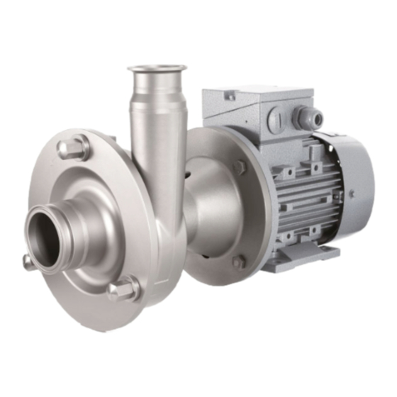
- Page 1 Original Instructions Assembly Instructions Centrifugal Pump FP Series Pump Type: Pump No.:...
- Page 2 Copyright © Copyright 2012 Fristam Pumpen KG (GmbH & Co.) All rights reserved. The contents, including graphic images and layout of this operating instructions manual are subject to copyright protection and to other laws for the protection of intellectual property. The publication and modification of the contents are not authorised.
-
Page 3: Table Of Contents
Table of Contens Connection of Sealing or Quenching Introduction..........5 Liquid (Optional) ........... 13 Foreword..............5 Cleaning..............13 Manufacturer............5 Scope of Supply............5 Operation ..........13 Pump Without Motor (Optional) ...... 5 Safety Instructions ..........13 Scope of Documentation........5 Commencement of Operation...... - Page 4 / / FP PUMP SERIES / / / Appendix 2 – Assembly Instructions (Optional) ........... 34 11.1 Safety Instructions..........34 11.2 Scope................34 11.3 Rating Plate .............. 34 11.4 Moving Without Motor........34 11.5 Installation Location ..........35 11.6 Pump Installation........... 35...
-
Page 5: Introduction
1 Introduction – Documentation on Fristam accessories (if applicable) – Certificates (materials certificates, etc.), if applicable – Declaration of Conformity or Declaration of Incorporation Foreword This operator's manual describes all FP centrifugal pump sizes, models, and versions. Display Conventions Information on the model, size, and version of your pump can List items are preceded by dashes: be found on the rating plate on your pump and in the "Order- –... -
Page 6: Safety
/ / FP PUMP SERIES / / / 2 Safety 2.4.2 Hot Surface Basic Safety Instructions ► Please read this operator's manual completely before using Fig. 2 Safety label: "Hot Surface" the pump and keep it available at the pump installation location. -
Page 7: Disposal
3 Design and Function Noise Generated by Running Pump Principles of Design Hearing damage. ► Wear ear protectors when using pumps with specified sound pressure levels of greater than 80 dBA. Disposal 2.6.1 Disposal of Transportation Package ► Recycle the transportation package. 2.6.2 Models KF and L 1: Disposal of Grease ►... -
Page 8: Models
/ / FP PUMP SERIES / / / Impeller (13) Electric Motor (19) Open impellers are standardly used in the FP pump series. The following motor types can be mounted: – IEC standard motor with drive side fixed bearing (A side), Pump Cover (14) feather key and shaft pin of the following types: The connection for the suction line is located on the pump... -
Page 9: Pump Key
3.2.3 Model KF (24) Supplementary Character 2 A, B ,C ,D Versions; see Chapter 3.4, "Versions," page 9: Compact bearing support with base L1, L2, L3 Bearing block with coupling Stainless steel lantern, double shaft seal, ø75mm at lantern neck Fig. -
Page 10: Storage
/ / FP PUMP SERIES / / / 4.1.2 Moving With Industrial Trucks 3. Guide both loops to the crane hook and rotate by 180° to en- sure that the belt will not slip on the hook. Preparation 4. For double shaft seal: ►... -
Page 11: Long-Term Storage
Long-Term Storage Installation Location For a storage time of longer than six months, heed the For standard pumps, the installation location must meet the following: following requirements: ► The shaft seals must be specially treated before long-term – Nonexplosive atmosphere storage: –... -
Page 12: Electrical Connection
/ / FP PUMP SERIES / / / ► Versions B and D: Screw the pump on the compact bearing support with base to the foundation. Model L ► Versions A and C: Set up the pump on the spherical cap bearings and align. ►... -
Page 13: Connection Of Sealing Or Quenching Liquid (Optional)
Connection of Sealing or Quenching Liquid 7 Operation (Optional) In versions with double shaft seal, the seal chamber must be Safety Instructions flushed with a sealing or quenching liquid. ► Danger of burning: Pumping of hot media can cause the ►... -
Page 14: Monitoring Of Operation
CIP Process 4. Turn on the motor. The pump now pumps against the closed The FP series pumps are suitable for the CIP (Cleaning In Place) valve in the discharge line. This will limit the starting current. process. The following guidelines apply to the CIP process: 5. -
Page 15: Safety Instructions
Safety Instructions Inspection of Sealing and Quenching Liq- uid (Optional) ► Danger of burning: Pumping of hot media can cause the pump to become very hot. Check the temperature before For pumps equipped for "locking system" or "quenching touching the pump. system,"... - Page 16 / / FP PUMP SERIES / / / Type Oil Volume L 4V 13 liters Table 3 Oil volumes 9.5.3 Model L1 ► Do not relubricate the deep groove ball bearing, but replace it completely. – At constant operating conditions, the raising of power con- sumption, noise level or vibration indicates that wear has oc- curred.
-
Page 17: Motor Replacement
6. Mount the shaft and align (see Chapter 9.11, "Models FPE and FP…V: Mounting and Alignment of the Pump Shaft," page 27). 7. Mount the lantern. 8. Only for flange connection: Check the clearance if necessary (see Chapter 9.9, "Checking of the Clearances," page 18). 9. -
Page 18: Shaft Seal Replacement
/ / FP PUMP SERIES / / / Shaft Seal Replacement The shaft seal must be replaced if: – Pumping medium or sealing or quenching liquid flows out of the pump on the atmosphere side. – Sealing liquid leaks into the pumping medium. Procedure 1. - Page 19 9.9.1 Measurement of the Impeller–Pump Cover Clear- ance 1. Measure the height H of the pump cover (44) using vernier calipers. Fig. 30 Impeller–casing clearance 9.9.3 Measurement of the Impeller–Casing Clearance 1. Measure dimension B between the shaft shoulder and the Fig.
-
Page 20: Pump Head Attachment
/ / FP PUMP SERIES / / / 4. Adjust the clearance to the values specified in Table 6 , Pump Size Clearance FPS in mm "Standard Clearence," page 20, Table 7 , "Clearances in model Impeller / pump cover Impeller / casing S,"... - Page 21 9.10.1 Clearance Setting for Flange Connection Applica- Pump Shaft Pump Sizes tion Case Seal Note: For pumps with flange connections, the clearance is set using shims. To determine the exact number and thicknesses of With quench 340/350/740, with clamp connection: ø 100 mm shims needed, first mount the impeller nut, the impeller, and 1150/1230/750, with flange the key as follows and then remove again.
- Page 22 / / FP PUMP SERIES / / / 1. Glue the cylindrical pin (562.60) into the mechanical seal Application Case B chamber (47-2.60) with a retaining compound. 412.10 412.60 412.62 Note: Glue the cylindrical pins into the mechanical seal 47-1.60 474.50 chamber so that they do not touch the shaft when the unit is 472.50...
- Page 23 Application Case C 543.60 478.60 474.60 472.60 412.65 475.60 412.62 412.64 412.63 562.60 543.60 Fig. 40 Application case C, completion of assembly on the shaft (III) Fig. 38 Application case C To complete assembly on the shaft (III): 6. Apply a retaining compound to the cylindrical pin (562.60), In the above figure, parts are grouped according to assembly and glue cylindrical pin into the spacer bushing (543.60).
- Page 24 / / FP PUMP SERIES / / / Application Case D gaged in the bores of the stationary seal ring (475.60). If the stationary seal ring does not feature holes, the cylindrical pins must engage in the longitudinal recesses in the station- ary seal ring (see "Sectional drawing of shaft seal").
- Page 25 Application Case E Application Case F Fig. 46 Standard shaft seal, application case F Fig. 44 Application case E Pump-side shaft seal In the above figure, parts are grouped according to assembly steps: Motor-side shaft seal Assembly of the shaft seal on the shaft on the motor side To assemble the motor-side shaft seal (IV) on the shaft: Assembly of the shaft seal on the shaft on the pump side 412.53...
- Page 26 / / FP PUMP SERIES / / / ► Slide the preassembled pump casing (52) with the shims 9.10.4 Mounting of the Impeller (53) over the shaft to the flange (54) and screw on (see Chapter 10.1, "Specifications," page 28). Pump With Clamp Connection Fig.
-
Page 27: Models Fpe And Fp
9.11 Models FPE and FP…V: Mounting and 10. Straighten the pump shaft if necessary. Alignment of the Pump Shaft Note: After the IEC motor has been replaced the pump shaft 9.12 Model L: Coupling Replacement must be mounted and aligned. Only use couplings approved by Fristam. -
Page 28: Specifications
/ / FP PUMP SERIES / / / 10 Appendix 1 10.1.2 Noise Emissions Pump Size Noise Level 10.1 Specifications 711/712 721/722 10.1.1 Tightening Torques for Screws and Nuts 741/742 Material: Steel, Strength Class: 8.8 751/752 Thread 3401/3402 Tightening 3521/3522 Torque [Nm] 3531/3532 Material: Stainless Steel, Strength Class: 70... -
Page 29: Troubleshooting Table
10.3 Troubleshooting Table Problem Possible Cause Remedy Pump either does not pump or pumps irregu- Suction line blocked/clogged. Open/clean suction line. larly. Suction filter contaminated. Clean suction filter. Discharge-side shut-off valve closed. Open discharge line. Pump not completely filled with Install pipe system so that casing is still filled with liquid. - Page 30 / / FP PUMP SERIES / / / Problem Possible Cause Remedy Flow noise. Operation contrary to design in overload Adjust working point to design. or part-load range. Flow losses in suction line too high. Increase nominal sizes; shorten line; prevent outgassing.
-
Page 31: Number Key
10.4 Number Key The general number key refers to the appended "Sectional drawings“. The part numbers conform to DIN 24250. Part Name Part Name Part Name Number Number Number Pump casing Mechanical seal spring Valve spring Stage casing Right spring Valve plate Cover Left spring... - Page 32 / / FP PUMP SERIES / / / Part Name Number Woodruff key spring...
-
Page 33: Ec Declaration Of Conformity
10.5 EC Declaration of Conformity 10.6 EG Declaration of Incorporation The manufacturer: FRISTAM Pumpen KG (GmbH&Co.) The manufacturer: FRISTAM Pumpen KG (GmbH&Co.) Kurt-A.-Körber-Chaussee 55 Kurt-A.-Körber-Chaussee 55 21033 Hamburg, Germany 21033 Hamburg, Germany declares that the following product (pump with motor): declares that the following product (pump without motor): –... - Page 34 / / FP PUMP SERIES / / / 11 Appendix 2 – Assembly Instructions 11.4 Moving Without Motor (Optional) Transportation may only be performed by trained personnel. The pump can be moved using an industrial truck or a crane. 11.1 Safety Instructions Always move the pump in the installation condition.
- Page 35 11.4.3 Moving With Crane To move the L pump with the round sling: Procedure 1. Wrap the round sling twice around the back end of the Falling Parts bearing block (see Fig. 57, "Moving with crane," page 35). Death from crushing, pinching of extremities, material damage. 2.
- Page 36 / / FP PUMP SERIES / / / Incorrectly Designed Motor and Coupling Destruction of pump and coupling. ► Only use motors and couplings that have been adapted to the pump characteristic curves. If you have any questions, please contact Fristam. Note: Please see the coupling supplier documentation for reference dimensions for the coupling.
- Page 38 / / FP PUMP SERIES / / /...
- Page 40 Fristam Pumpen KG (GmbH & Co.) Kurt-A.-Körber-Chaussee 55 21033 Hamburg GERMANY Tel.: +49-40-72556-0 Fax: +49-40-72556-166 E-mail: info@fristam.de EN 05-2017 - Rev. 4.3 FP Pump Series...
Need help?
Do you have a question about the FPE and is the answer not in the manual?
Questions and answers