
Related Manuals for Fristam Pumps FSP Series


Summary of Contents for Fristam Pumps FSP Series
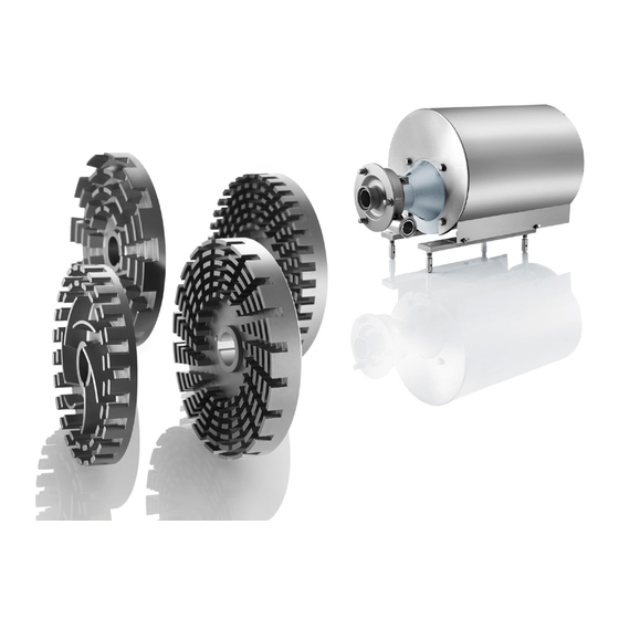
- Page 1 Original Instructions Assembly Instructions Shear Pumps (Rotary Homogenizers) FSP Series Pump Type: Pump No.:...
- Page 2 Copyright © Copyright 2010 Fristam Pumpen KG (GmbH & Co.) All rights reserved. The contents, including graphic images and layout of this operat- ing instructions manual are subject to copyright protection and to other laws for the protection of intellectual property. The publication and modification of the contents are not authorised.
-
Page 3: Table Of Contents
Table of Contents Introduction..........5 Electrical Connection ........... 12 Connection of Sealing or Quenching Foreword..............5 Liquid (Optional)............ 12 Manufacturer............5 Cleaning..............12 Scope of Supply............5 Pump Without Motor (Optional) ...... 5 Operation ..........13 Scope of Documentation........5 Safety Instructions .......... - Page 4 / / FSP SERIES / / / Appendix 2 – Assembly Instructions (Optional) ........... 33 11.1 Safety Instructions..........33 11.2 Scope................33 11.3 Rating Plate .............. 33 11.4 Moving Without Motor........33 11.5 Installation Location ..........34 11.6 Pump Installation........... 34...
-
Page 5: Introduction
– Supplier Documentation (motor, coupling, etc.) Foreword – Declaration of Conformity or Declaration of Incorporation This operator's manual describes all FSP Series sizes, models, and versions. – Documentation on Fristam accessories (if applicable) Information on the model, size, and version of your pump can –... -
Page 6: Intended Use
Intended Use This label indicates that the pump cannot be run dry. There The standard FSP Series versions are designed for use in the must always be medium in the suction line and the pump when food industry, the pharmaceutical and biotechnology industry, the pump is started. -
Page 7: Disposal
The local noise exposure regulations must be complied Lantern with. For noise emission values for the pumps, please see Electric motor Chapter 10.1, "Specifications" page 27. 3.1.1 Pump Head (A) Disposal 2.6.1 Disposal of Transportation Package Recycle the transportation package. 2.6.2 Models KF and L 1: Disposal of Grease ... -
Page 8: Models
/ / FSP SERIES / / / 3.1.2 Lantern (B) and Electric Motor (C) 3.2.1 Models FSPE and FSP...V Fig. 8 Model FSPE Motor: IEC standard motor, model B3/B5 Design: With lantern Fig. 7 Lantern and electric motor 3.2.2 Model KF... -
Page 9: Versions
4 Transportation (21) Pump Type FSPE Attached pump shaft Transportation may only be performed by trained personnel. FSP...V Extended insert shaft as pump shaft The pump can be moved using an industrial truck or a crane. (22) Supplementary Character 1 High-pressure pump Safety Instructions Pump casing with circulation line... -
Page 10: Storage
/ / FSP SERIES / / / 5 Storage Only use hoists that are designed for the total weight of the pump. Ensure that the area below the pump is clear of people. Safety – Corrosion: Condensation can build up under a tarp and de- stroy the pump. -
Page 11: Installation
6 Installation 6.3.2 Secondary Measures Take structural measures such as the following: – Acoustic paneling Safety Instructions – Enclosure in housing – Danger of injury from falling parts. Wear safety shoes. Pump Fixation Check load capacity and attachment of hoists. –... -
Page 12: Electrical Connection
/ / FSP SERIES / / / Connection of Sealing or Quenching Liquid Design pipe cross section so that no unnecessary pressure losses or cavitation occurs in the suction area. (Optional) Verify this in the project planning stage. In versions with double shaft seal, the seal chamber must be flushed with a sealing or quenching liquid. -
Page 13: Operation
7 Operation Damage to Double Shaft Seals Safety Instructions If the pump runs without a sealing medium, the shaft seal will be damaged. – Danger of bursting: If the allowable pressure or temperature range is exceeded, the pump may burst or become leaky. Ensure that during operation: ... -
Page 14: Stopping Of Operation
3. Close the valve in the discharge line. The FSP Series pumps can only be used with the SIP (Steriliza- tion In Place) process with the prior approval of Fristam. Suitability depends on the selected elastomers. The maximum Pump Decommissioning process temperature is 145°C. -
Page 15: Safety Instructions
Safety Instructions The sealing liquid is heated by hot pumping medium and by op- eration of the pump. – Danger of injury: Rotating parts. Ensure that the temperature T of the sealing liquid is < 70°C Before removing the coupling guard and the guard plate, during operation. - Page 16 / / FSP SERIES / / / Note: All parts that are gray in the above two figures remain Model Bearing Grease Amount on the shaft. 10 g 5. Clean the surfaces of all parts and check for damage. Replace Table 5 Bearing grease amount: model L1 if necessary.
-
Page 17: Motor Replacement
4. Remove the outer race of the cylindrical roller bearing. Note: All parts that are gray in the above figure remain on the shaft. 5. Clean the surfaces of all parts and check for damage. Replace Fig. 22 Parallel misalignment if necessary. -
Page 18: Checking Of The Clearances
/ / FSP SERIES / / / Procedure Fig. 24 Dismantling of pump cover 1. Loosen the nuts (36) on the pump cover (37). 2. Remove the nuts, the washers, the pump cover, and the cov- Fig. 26 Removing impeller er seal (38). -
Page 19: Pump Head Attachment
9.9.1 Measurement of the Impeller–Pump Casing Clear- ance Prerequisites – Pump cover has been removed. – Pump casing is connected firmly to the lantern. – The impeller has been mounted and the impeller nut tight- ened. Procedure 1. Measure the clearance Z between the pump casing (47) and the impeller (46) using vernier calipers. - Page 20 / / FSP SERIES / / / Preparation 8. If the clearance is incorrect: Clean all pump parts and check for damage and accuracy of Adjust the clearance using the appropriate shims. fit. If necessary, rework or replace pump parts.
- Page 21 472.60 93-1.60 412.62 412.64 474.60 474.63 475.60 412.65 412.60 412.61 47-2.60 485.60 478.60 412.63 Fig. 32 Application case A, completion of assembly on the shaft To complete assembly on the shaft (II): 9. Equip the rotating seal ring (472.60) with an O-ring (412.63).
- Page 22 / / FSP SERIES / / / To preassemble the shaft (I): 11. Equip the rotating seal ring (472.60) with an O-ring (412.63). Caution! Cutting injuries from sharp-edged shaft protective sleeves. Wear suitable protective gloves. 12. Equip the rotating seal ring with the thrust collar (474.60) and the spring (478.60) and slide onto the shaft.
- Page 23 412.64 474.60 412.63 412.62 412.65 524.60 412.61 93-1.60 47-2.60 474.63 472.60 485.60 478.60 Fig. 38 Application case C, completion of assembly on the shaft (III) To complete assembly on the shaft (III): 421.60 8. Equip the rotating seal ring (472.60) with an O-ring 562.60 (412.63).
- Page 24 / / FSP SERIES / / / 9.10.3 Mounting of the Pump Casing 472.61 474.61 50.62 50-3.60 Pump With Flange Connection 904.61 412.66 479.60 Fig. 40 Application case D, assembly of motor-side shaft seal (I) To assemble the shaft seal on the motor side (I): 1.
- Page 25 Thread Tightening Torque 100 Nm 200 Nm Table 9 Tightening torques for impeller nuts 8. Adjust the clearances by sliding the pump head inside the clamp connection. See Chapter 9.9, "Checking of the Clearanc- es" page 18. Align the surface of the outlet side (discharge line connection) horizontally while doing so.
-
Page 26: Pump Shaft Mounting And Alignment
/ / FSP SERIES / / / 9.11 Pump Shaft Mounting and Alignment – Motor > 30 kW: max. runout tolerance = 0.08 mm 10. Straighten the pump shaft if necessary. 9.11.1 Models FSPE and FSP...V Note: After the IEC motor has been replaced the pump shaft 9.12 Model L: Coupling Replacement... -
Page 27: Appendix
10 Appendix 10.1.2 Noise Emissions Pump Size Impeller Noise Level 10.1 Specifications 711/712 Teeth Impeller 10.1.1 Tightening Torques for Screws and Nuts 3521/3522 Teeth Material: Steel, Strength Class: 8.8 Impeller Thread 3531/3532 Teeth Tightening Impeller Torque [Nm] 3541/3542 Teeth Material: Stainless Steel, Strength Class: 70 Impeller 3551/3552 Teeth... -
Page 28: Troubleshooting Table
/ / FSP SERIES / / / 10.3 Troubleshooting Table Problem Possible Cause Remedy Pump either does not pump or pumps irregu- Suction line blocked or clogged. Open or clean suction line. larly. Suction filter contaminated. Clean suction filter. Discharge-side shut-off valve closed. - Page 29 Problem Possible Cause Remedy Flow noise. Operation contrary to design in overload Adjust working point to design. or part-load range. Flow losses in suction line too high. Increase nominal sizes; shorten connection lines; prevent outgassing. Cavitation. Check condition for NPSH rating; contact Fristam.
-
Page 30: Number Key
/ / FSP SERIES / / / 10.4 Number Key The number key is for the attached "Sectional Drawing.". The part numbers are consistent with DIN 24250. Part Num- Name Part Num- Name Part Num- Name Pump casing Mechanical seal spring... - Page 31 Part Num- Name Spring...
-
Page 32: Ec Declaration Of Conformity
/ / FSP SERIES / / / 10.5 C Declaration of Conformity 10.6 EG Declaration of Incorporation The manufacturer: FRISTAM Pumpen KG (GmbH&Co.) The manufacturer: FRISTAM Pumpen KG (GmbH&Co.) Kurt-A.-Körber-Chaussee 55 Kurt-A.-Körber-Chaussee 55 21033 Hamburg, Germany 21033 Hamburg, Germany declares that the following product (pump with motor): declares that the following product (pump without motor): –... - Page 33 11 Appendix 2 – Assembly Instructions 11.4 Moving Without Motor (Optional) Transportation may only be performed by trained personnel. The pump can be moved using an industrial truck or a crane. 11.1 Safety Instructions Always move the pump in the installation condition. These assembly instructions are addressed solely to specialized employees.
- Page 34 / / FSP SERIES / / / 11.4.3 Moving With Crane To move the L pump with the round sling: Procedure 1. Wrap the round sling twice around the back end of the bear- Falling Parts ing block (see Fig. 53 "Moving with crane" page 34).
- Page 35 Incorrectly Designed Motor and Coupling Destruction of pump and coupling. Only use motors and couplings that have been adapted to the pump characteristic curves. If you have any questions, please contact Fristam. Note: Please see the coupling supplier documentation for refer- ence dimensions for the coupling.
- Page 36 Fristam Pumpen KG (GmbH & Co.) Kurt-A.-Körber-Chaussee 55 21033 Hamburg GERMANY Tel.: +49-40-72556-0 Fax: +49-40-72556-166 E-mail: info@fristam.de FSP Series EN(US) 06-2017 - Rev. 2.3...
Need help?
Do you have a question about the FSP Series and is the answer not in the manual?
Questions and answers