
Related Manuals for Fristam Pumps FKL Series


Summary of Contents for Fristam Pumps FKL Series
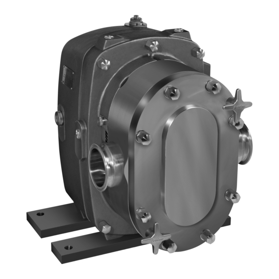
- Page 1 Original Instructions Assembly Instructions Positive Displacement Pump FKL Series Pump Type: Pump No.:...
- Page 2 Copyright © Copyright 2010 Fristam Pumpen KG (GmbH & Co.) All rights reserved. The contents, including graphic images and layout of this operating instructions man- ual are subject to copyright protection and to other laws for the protection of intellectual property. The publication and modification of the contents are not authorised.
-
Page 3: Table Of Contents
Table of Contents Introduction..........5 Reduction of Sound and Vibration ....11 Pump Fixation ............11 Foreword..............5 Installation of Pipes ..........11 Manufacturer............5 Electrical Connection........... 12 Scope of Supply............5 Connection of Sealing or Quenching Pump Without Motor (Optional) ...... 5 Liquid (Optional) ........... - Page 4 / / FKL PUMP SERIES / / / Appendix 1 ..........28 11.1 Specifications ............28 11.2 Maintenance Intervals.......... 29 11.3 Troubleshooting Table ........29 11.4 Number Key ............. 30 11.5 EC Declaration of Conformity......32 11.6 EG Declaration of Incorporation....... 32 Appendix 2 –...
-
Page 5: Introduction
1 Introduction – Attached documents – Order-Related Documents – Supplier documentation (motor, coupling, etc.) Foreword – Documentation on Fristam accessories (if applicable) This operator's manual describes all sizes, models, versions, and accessories of the FKL Pump Series. – Certificates (materials certificates, etc.), if applicable ►... -
Page 6: Safety
/ / FKL PUMP SERIES / / / 2 Safety Impermissible Temperature Range Personal injury and material damage from leakage or bursting of pump. Basic Safety Instructions ► Maintain the pump temperature within the specified tem- ► Please read this operator's manual completely before using perature range. -
Page 7: Noise Emissions
Disposal 2.5.2 No Dry Running 2.7.1 Disposal of Transportation Package ► Recycle the transportation package. 2.7.2 Disposal of Grease ► Dispose of grease and objects saturated with grease in an Fig. 2 Safety label: "No Dry Running" environmentally friendly manner in accordance with appli- cable regulations. -
Page 8: Models
/ / FKL PUMP SERIES / / / Basic Versions 3.1.1 Pump With Synchromesh Gears (A) The model version is indicated on the rating plate. (see Chapter 2.5.3, "Rating Plate," page 7). For all models, the following versions are available: –... -
Page 9: Accessories
Accessories Safety Instructions The FKL Pump Series can be equipped with the following acces- Falling or Unsecured Parts sories, among others: Severe crush injuries. – Enclosure ► Always wear gloves when performing transportation-related Stainless steel enclosure for the gear motor. The enclosure is work. -
Page 10: Moving With Crane
/ / FKL PUMP SERIES / / / Moving With Crane WARNING Falling Parts Death from crushing, severe pinching of extremities, material damage. ► Only use suitable means of conveyance and hoists. Informa- tion on the pump weight can be found on the pump's rating plate as well as in the Order-Related Documents in the at- tached documents. -
Page 11: Installation
6 Installation 6.3.2 Secondary Measures ► Take structural measures such as the following: – Acoustic paneling Safety Instructions – Enclosure in housing Falling or Unsecured Parts Severe crush injuries. Pump Fixation Always wear gloves when performing installation-related ► work. 6.4.1 Pump With Base Frame Incomplete, Unstable Installation ►... -
Page 12: Electrical Connection
/ / FKL PUMP SERIES / / / Pressure Suction side side Inlet Outlet Fig. 12 Air pocket in pipe Fig. 14 Direction of rotation left Fig. 13 Dip in pipe Suction side Pressure side ► Run pipe connections in accordance with: Inlet Outlet pressure, temperature and type of pumping medium. -
Page 13: Cleaning
Cleaning If no pressure is noted in the "Sectional drawing of the shaft seal", the following applies: Only use cleaning agents that comply with the hygiene guide- – A max. pressure of 0.2 bar is allowed for seals to which lines for the respective pumping medium. -
Page 14: Stopping Of Operation
/ / FKL PUMP SERIES / / / Stopping of Operation 3. Perform intermediate flush with water. 4. Perform acid flush with nitric acid (HNO seeTable 2 , "CIP 1. Turn off the motor. cleaning," page 14). 2. Close the valve in the suction line to prevent dry running of 5. -
Page 15: Maintenance
10 Maintenance 10.3 Inspection of Sealing and Quenching Liq- uid (Optional) For information on maintenance intervals, please see For pumps equipped for "locking system" or "quenching sys- Chapter 11.2, "Maintenance Intervals," page 29. tem" the sealing liquid head must be checked. For information on maintenance intervals, please see Table 26 on page 29. -
Page 16: Lubrication Of Motor Bearings
/ / FKL PUMP SERIES / / / 10.7 Shaft Seal Replacement Bleed screw Screw plug Replace the shaft seal if: Oil level sight glass – Pumping medium or sealing or quenching liquid flows out of the pump on the atmosphere side. Procedure –... - Page 17 1. Loosen the nuts (25) on the pump cover. 7. Loosen and remove the hex cap screws (30) on the pump casing. 2. Remove the nuts, (25), the pump cover (26), and the cover seal (27). 8. Carefully detach the pump casing (31) from the gearbox (32).
-
Page 18: Mounting Of The Pump Casing
/ / FKL PUMP SERIES / / / WARNING Pump size 25-600 Rotating machine parts. Severe pinching of hands. ► Block the rotors (38) with wooden or plastic wedges. 3. Loosen and remove the rotor fasteners (37) and the belonging seals. 4. - Page 19 Tip: The joint retaining compound "Euro Lock A64.80," e.g., is suit- Preassembly of pump casing: able for gluing in bearings and bushings. Tip: The screw retaining compound "Euro Lock A24.10," e.g., is suit- able for gluing in set screws. 10.9.1 Mounting of the Shaft Seals 475.60 The shaft seal built into the respective pump is given in the Or- 477.60...
- Page 20 / / FKL PUMP SERIES / / / CAUTION Pump size Casing screws Mount the rotating seal ring so that it fits onto the shaft face. ► Tightening Torque [Nm] 15 - 20 Preassembly of pump casing: Table 6 Tightening torque for casing screws 8.
- Page 21 CAUTION Case D Preassembly on shaft: Align the key to the cylindrical pins of the mechanical seal ► chamber. 412.63 6. Insert the O-ring (412.67) into the mechanical seal chamber. 7. Insert the spacer ring (504.60) into the mechanical seal 472.60 chamber.
- Page 22 / / FKL PUMP SERIES / / / CAUTION Case E Preassembly on shaft: Align the stationary seal ring to the cylindrical pins of the ► mechanical seal chamber. 412.63 8. Secure the parts with the snap ring (93-1.60). Final assembly of pump casing: 472.60 9.
- Page 23 5. Insert the key (477.61) into the mechanical seal chamber. Case F Preassembly on shaft: CAUTION ► Align the key to the cylindrical pins of the mechanical seal chamber. 412.63 6. Insert the O-ring (412.67) into the mechanical seal chamber. 472.60 7.
- Page 24 / / FKL PUMP SERIES / / / CAUTION 1. Insert the O-rings (50) in the grooves on the rotors. Note: Only for pump size 15-20: Insert the keys for the rotors Align the stationary seal ring to the cylindrical pins of the ►...
-
Page 25: Shaft Bearing Replacement
1. Equip the pump cover (53) with an O-ring (54). 2. Unscrew the forcing screws (52). The forcing screws should be flush with the inside wall of the pump cover. 3. Slide the pump cover onto the pump casing (55). Fig. -
Page 26: Checking Of The Clearances
/ / FKL PUMP SERIES / / / 10.13 Checking of the Clearances 20 bar Rotors Pump size Axial Clearance [mm] Radial Clearance [mm] The clearance ensures that the rotors can rotate freely. The clearance must be checked if the following parts are replaced: FKL 250 0.14 - 0,19 0.23 - 0.30... - Page 27 10.13.2 Measurement of Radial Clearance Clearances are outside of the range of tabulated values. – Radial clearance Contact Fristam to order the documents for repinning of ► the pump casing. – Axial clearance ► Contact Fristam. Fig. 40 Measurement of radial clearance 1.
-
Page 28: Specifications
/ / FKL PUMP SERIES / / / 11 Appendix 1 11.1 Specifications 11.1.1 Tightening Torques for Screws Fastener for FKL 15 FKL 20 FKL25 FKL50 FKL75 FKL150 FKL205 FKL250 FKL 400 FKL580 FKL600 Pump Cover Rotor Pump Casing — —... -
Page 29: Maintenance Intervals
11.2 Maintenance Intervals Interval Model Maintenance Task Chapter Once a day Check the oil level. See Chapter 10.4, "Oil Level Check," page 15. Once a day "Sealing and Quenching Liquid" Check the sealing or quenching liquid. See Chapter 10.3, "Inspection of Sealing and Quen- option ching Liquid (Optional),"... - Page 30 / / FKL PUMP SERIES / / / Problem Possible Cause Remedy Metal noise. Foreign objects in pump interior. Disassemble, inspect, and (if necessary) repair. Rotor mechanically jammed, rotor fastener loose. Disassemble, rework, and set correct clearance. Excessive wear of bearings and gearwheels from Disassemble, inspect, and repair....
-
Page 31: Number Key
11.4 Number Key The number key is for the attached Sectional Drawings. The part numbers conform to DIN 24250. Part Name Part Name Part Name Number Number Number Pump casing Mechanical seal spring Valve spring Stage casing Spring - right hand Valve plate Cover Spring - left hand... - Page 32 / / FKL PUMP SERIES / / / Part Name Number Woodruff key spring...
-
Page 33: Ec Declaration Of Conformity
11.5 EC Declaration of Conformity 11.6 EG Declaration of Incorporation The manufacturer: FRISTAM Pumpen KG (GmbH&Co.) The manufacturer: FRISTAM Pumpen KG (GmbH&Co.) Kurt-A.-Körber-Chaussee 55 Kurt-A.-Körber-Chaussee 55 21033 Hamburg, Germany 21033 Hamburg, Germany declares that the following product (pump with motor): declares that the following product (pump without motor): –... -
Page 34: Appendix 2 - Assembly Instructions (Optional)
/ / FKL PUMP SERIES / / / 12 Appendix 2 – Assembly Instructions rated speed [1/min]; without drive: no indication (Optional) Q: flow rate [m³/h]; without drive: no indication 12.1 Safety Instructions 12.4 Moving Without Motor These assembly instructions are addressed solely to specialized Transportation may only be performed by trained personnel. -
Page 35: Installation Location
Fig. 44 Moving with pallet truck 12.4.3 Moving With Crane WARNING Falling Parts Death from crushing, severe pinching of extremities, material damage. Only use suitable means of conveyance and hoists that are ► designed for the total weight of the pump. Information on the pump weight can be found on the Fig. - Page 36 / / FKL PUMP SERIES / / / NOTICE Incorrectly Designed Motor and Coupling Destruction of pump and coupling. ► Only use motors and couplings that have been adapted to the pump characteristic curves. If you have any questions, please contact Fristam. Note: Please see the coupling supplier documentation for refer- ence dimensions for the coupling.
- Page 38 / / FKL PUMP SERIES / / /...
- Page 40 FRISTAM Pumpen KG (GmbH & Co.) Kurt-A.-Körber-Chaussee 55 21033 Hamburg GERMANY Tel.: +49 (0) 40 / 7 25 56 -0 Fax: +49 (0) 40 / 7 25 56 -166 E-Mail: info@fristam.de FKL Pump Series EN(US) 10-2020 Rev. 3.4...
Need help?
Do you have a question about the FKL Series and is the answer not in the manual?
Questions and answers