
Related Manuals for Fristam Pumps FPM Series


Summary of Contents for Fristam Pumps FPM Series
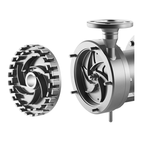
- Page 1 English translation of the original German Operating Manual Centrifugal pump FPM Series, Rotary Homogenizers FSM Series Pump type: Pump no.:...
- Page 2 Copyright © Copyright 2016 Fristam Pumpen KG (GmbH & Co.) All rights reserved. The contents of this operating manual, including images and design, are subject to the protection of copyrights and other trade-related intellectual property rights. It is not permitted to disseminate or alter the content of this manual. Nor may the said content be copied, disseminated, altered or made available to third parties for commercial purposes.
-
Page 3: Table Of Contents
Introduction..........3 Operation........... 10 Foreword..............Safety instructions..........10 Manufacturer ............Commencement of Operation ......10 Scope of Supply............. Monitoring of Operation ........11 Scope of documentation ........Stopping of Operation ........11 Display Conventions..........Decommission pump........... 11 Cleaning during operation ........ 12 Safety............ - Page 4 / / FPM AND FSM SERIES / / /...
-
Page 5: Introduction
1 Introduction Display Conventions List items are preceded by dashes: Foreword – Part 1, – Part 2. This operation manual describes all sizes, models and versions of the FPM and FSM series. Handling instructions that must be performed in a specified or- der are numbered: Information on the model, size, and version of your pump can be found on the rating plate on your pump and in the "Order-Re-... -
Page 6: Safety
/ / FPM AND FSM SERIES / / / 2 Safety Labels Do not alter or remove the labels on the pump. Basic safety instruction Immediately replace damaged or lost labels with ones that are true to the originals. ... -
Page 7: Noise Emission
Disposal 2.4.3 Direction of rotation 2.6.1 Disposal of Transportation Package Fig. 5 Label: "Impeller Direction of Rotation" Recycle the transportation package. This label shows the direction of rotation of the impeller. It is lo- cated at the front on the pump cover. 2.6.2 Disposal of pump 1. -
Page 8: Model
/ / FPM AND FSM SERIES / / / 3.1.1 Pump head (A) and lantern (B) 3.1.2 Electric motor (C) Fig. 9 Electric motor Electric power connection Electric motor Flange shaft Fig. 8 Pump head and lantern Lantern (17) The lantern connects the pump casing with the motor. Discharge line connection Magnetic coupling –... -
Page 9: Type Designation
Type designation 4 Transportation FPM 722 A Transportation may only be performed by trained personnel. The pump can be moved using an industrial truck or a crane. Fig. 11 Example of type designation Safety instructions Pump type – Danger of injury from falling or unsecured parts. Pump size ... -
Page 10: Moving With Crane
/ / FPM AND FSM SERIES / / / Moving With Crane 5 Storage WARNING Safety Falling parts – Corrosion: Condensation can build up under a tarp and de- Death from crushing, pinching of extremities, material damage. stroy the pump. ... -
Page 11: Installation
6 Installation Decouple the suction and discharge lines from vibrations. – Support lines. – Align lines. Safety instructions – Install vibration isolators. – Danger of injury from falling parts. Wear safety shoes. 6.3.2 Secondary measures Check load capacity and attachment of hoists. ... -
Page 12: Electrical Connection
/ / FPM AND FSM SERIES / / / 7 Operation Safety instructions – Danger of bursting: If the allowable pressure or temperature range is exceeded, the pump may burst or become leaky. Maintain the pump pressure and temperature within the specified ranges. -
Page 13: Monitoring Of Operation
During operation do not close the valve in the discharge NOTE line abruptly or for a long period of time. Separation of the magnetic field – Damage to pump: Exceeding the rated power can lead to damage to the pump and the magnetic coupling. Extraordinary loads during the start-up of the pump, caused by blocking of the impeller or excessive overload of the pump can ... -
Page 14: Cleaning During Operation
/ / FPM AND FSM SERIES / / / 9 Maintenance Example of a Cleaning Cycle 1. Perform preliminary flush with water. For information on maintenance intervals, please see 2. Perform caustic flush with soda lye (NaOH, see Table 3 "CIP Chapter 10.2 "Maintenance intervals", Page 18. -
Page 15: Changing The Motor
Changing the motor Thread Tightening torques 1. Turn off the motor and prevent it from being able to be turned on accidentally. 2. Remove the pump head. See Chapter 9.6 "Pump Head Remov- al", Page 13. 3. Take the lantern off of the motor. Table 5 Tightening torques of screws/motor shaft 4. -
Page 16: Checking Of The Clearances
/ / FPM AND FSM SERIES / / / 30 31 32 33 Fig. 18 Removing the impeller Fig. 20 Disassembling the pump casing 3. Loosen the impeller nut (28) and remove it including the O- ring (29) : 6. Loosen and remove the screws and washers (36). 3a. - Page 17 9.7.2 Measure the clearance impeller pump cover / pump type FSM Procedure 1. Measure the clearance Z between the pump casing (41) and the impeller (40) using vernier calipers. Note: In order to measure distance Z, the impeller must be pulled to the front in the direction of the pump casing.
-
Page 18: Mounting The Pump Head
/ / FPM AND FSM SERIES / / / Mounting the pump head The mounting of the pump depends on the respective size and model as well as on the respective magnetic coupling (see “Or- der-related documents”) in the enclosed documents. NOTE Incorrect elastomers Pump leakiness. - Page 19 9.8.1 Mount the impeller 9.8.2 Sealing the pump Fig. 28 Pump cover 44 45 46 47 Push the pump cover (51) onto the O-ring (52) . Tighten the nut (50) with the washer . Fig. 26 Installing the impeller 1.
-
Page 20: Specifications
/ / FPM AND FSM SERIES / / / 10 Appendix 1 10.1.2 Noise emission Pump size Noise level dB (A) 10.1 Specifications 711/712 721/722 10.1.1 Tightening torques for screws and nuts 741/742 Material: Steel, strength class 8.8 3531/3532 Thread 3541/3542 Tightening 3531/3532... -
Page 21: Troubleshooting Table
10.3 Troubleshooting table Problem Possible cause Remedy Pump either does not pump or pumps Suction line blocked or clogged. Open or clean suction line. irregularly. Suction filter contaminated. Clean suction filter. Discharge-side shut-off valve closed. Open discharge line. Viscosity of fluid too high Contact Fristam . - Page 22 / / FPM AND FSM SERIES / / / Problem Possible cause Remedy Flow noise Operation contrary to design in overload or part- Adjust working point to design. load range. Flow loss in suction line too high. Increase nominal sizes; shorten connection lines; prevent outgassing.
-
Page 23: Number Key
10.4 Number Key The general list of numbers refers to the enclosed “Sectional drawings”. The parts numbers comply with DIN 24250. Part no. Designation Part no. Designation Part no. Designation Pump casing Spring washer 90-5 Eye bolt Cover Washer Screw Outlet side Grooved pin Hex cap screw... -
Page 24: Ec Declaration Of Conformity
/ / FPM AND FSM SERIES / / / 10.5 EC Declaration of Conformity The manufacturer: Fristam Pumpen KG (GmbH&Co.) Kurt-A.-Körber-Chaussee 55 21033 Hamburg hereby declares that the following product (pump with motor): – Centrifugal pump models: FP, FPE, FP…V, FPH, FPEH, FPH…V, FSPE, FSP…V, FM, FZ, FC, CF, CFE, FPM, FSM –... - Page 25 Fristam Pumpen KG (GmbH & Co.) Kurt-A.-Körber-Chaussee 55 21033 Hamburg GERMANY Tel.: +49 (0) 40 / 7 25 56 -0 Fax: +49 (0) 40 / 7 25 56 -166 email: info@fristam.de FPM/FSM Series EN 03-2016 - Rev. 1.0...
Need help?
Do you have a question about the FPM Series and is the answer not in the manual?
Questions and answers